7. Electronics design
This week I worked on electronics design and it was a real challenge.
Research
As a beginner, I have started to follow the tutorial on fabcloud. A lot of information are overwhelming my mind, so I need sometimes to get back on the basis.
Electronic basics:
From 2021 to 2023, I was beginning from beginning and I found interesting « electronics for dummies » readings.
To my french fellows, you can find the free book
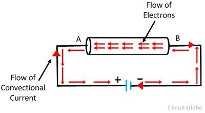
They say that the current is coming from the negative side to the positive one. The electrons are reaching the protons. When I was a child, I did not get the concept, and I gave up. Apparently the direction chosen at the very beginning of electricity was wrong and all calculations depend on this misundertanding choice.
Some rules have to be clear :
| Symbols | Functions | Units |
|---|---|---|
| P | Power | watts |
| I | Current | amps |
| U | Voltage | volts |
| R | Resistor | ohms |
| C | Conductance |
Useful rules:
U= R x I
P= I x U
P=U²/R
Resistors in serial : addition of resistances. Resistors in parallel : Rtotal= (R1xR2)/(R1+R2) also used as Rtotal = R1/R2
Here come some explanations on Sparkfun about :
In summary, represented in binary, an ON translates to a binary 1, and an OFF translates to a binary 0. In Arduino, these signals are HIGH or LOW, respectively.
I was quiet interested in it, I think I need to make some reel examples in order to understand the different mixes (parallel, serial)
-
pulse widh modulation My fellow Sylvain explained me a bit about the , in order to command a servo motor and dimming lights (atténutation ). But I think it will be more clear when I will go deeper.
I will come back later, there is so much things to know right now.
In 2020, I followed a french MOOC course about Arduino. Fun-MOOC is a french free plateform which delivers a lot of interesting courses.
 FUN-MOOC
In order to learn easily some knowledges about Arduino, I also bought a class book for childrens « Adventures for Arduino »
Becky Stewart explains the concept of Pull-up Resitor. Without it, the push button attached has no departure information. So to give it a signal, we are getting a « low » or « high » signal. However, the arduino got this « INPUT PULLUP » function.
https://learn.sparkfun.com/tutorials/pull-up-resistors
First try: (2021) following the fabacademy tutorial: Hello-World Board hello-ftdi-44
It was tough, I was not able to go to la Machinerie, so I have tried to make something by myself asking my colleague Thierry. He is in charge of the electronics department
///////////////////NOTE: PUT MORE BASICS OF ELECTRONICS//////////////////////////////////
Getting material
| Parts | Functions |
|---|---|
| 6-pin Programming Header | Used to program the board |
| Microcontroller - Attiny44A | Difference of potential energy between two pointOnce the microcontroller is programmed, the program stored in non-volatile memory, allowing itself to remember the program. |
| FTDI Header | Powers the board and allows board to talk to computer. |
| Resonator - 20MHz | Difference of potential energy between two points. It is measured External clock. The Attiny has a 8Mhz clock but the resonator is faster (increases the clock speed of the processor) and more accurate. |
| Resistor - value 10k ohm: | Purpose: pull-up resistor. |
| Resistor - value 499 ohms: | Purpose: current limiting resistor for LED. |
| Capacitor | 1uF |
| Button | 6mm Switch |
| LED (Light Emitting Diode): | LEDs have polarity - the side with the line is the cathode and connects to the ground side. |
| Ground | Ground |
| Vcc | Vcc |
The main part was missing, I ordored an attiny44 on Farnell and got it one day before the review…
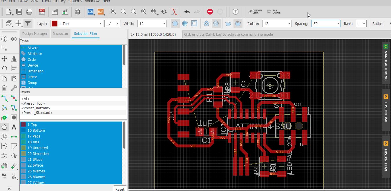
PCB design and electricalEagle-01-soft schematic software
the tutorial on week11 is more detailled:
I am going to learn Eagle:

EAGLE is electronic design automation (EDA) software that lets printed circuit board (PCB) designers seamlessly connect schematic diagrams, component placement, PCB routing, and comprehensive library content. from Autodesk. You can easily get a student version and install the software easily by downloading on autodesk.com
Well, I am discovering as a novice a new shield… I am not very comfortable, I did not have a chance to go to the Machinerie, so I am following the fabacademy tutorial
Redrawing Echo Hello-World Board
You need to download the schematic file called hello.fdti.44
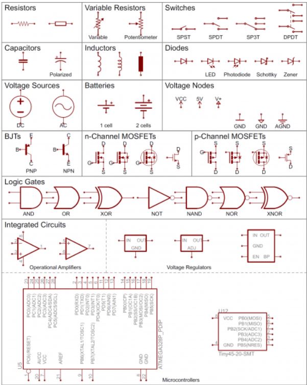
what is the schematic:
Schematic are our map to designing, building, and troubleshooting circuits. It is like the thinking part of your work.
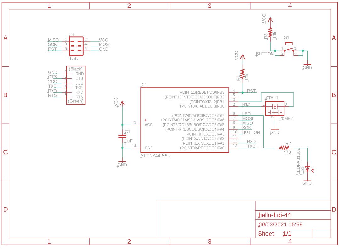
Here comes the main components to read on a schematic.
It is linked ot the board file hello-ftdi-44.brd
what is the board?Ӧ
You will get roughly the components and you imagine what you PCB will look like. Editing traces, moving components, designing your own exterior shape.
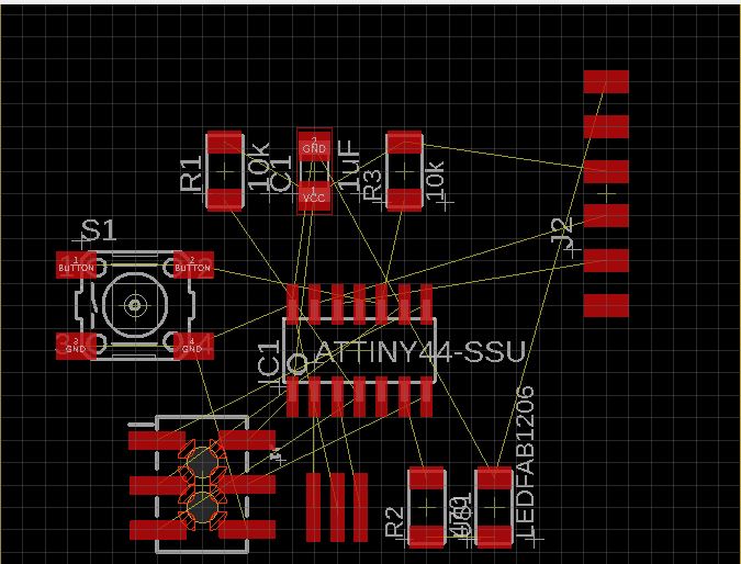 When the board is coming, it reminds me when you start a lego construction from scratch.
The board layout shows how the electrical components and traces will be laid out on the board.
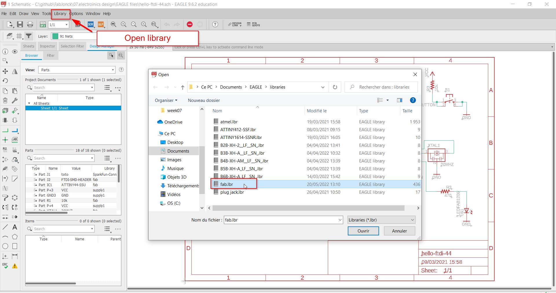
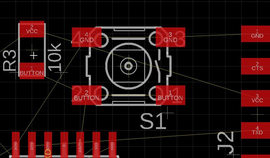
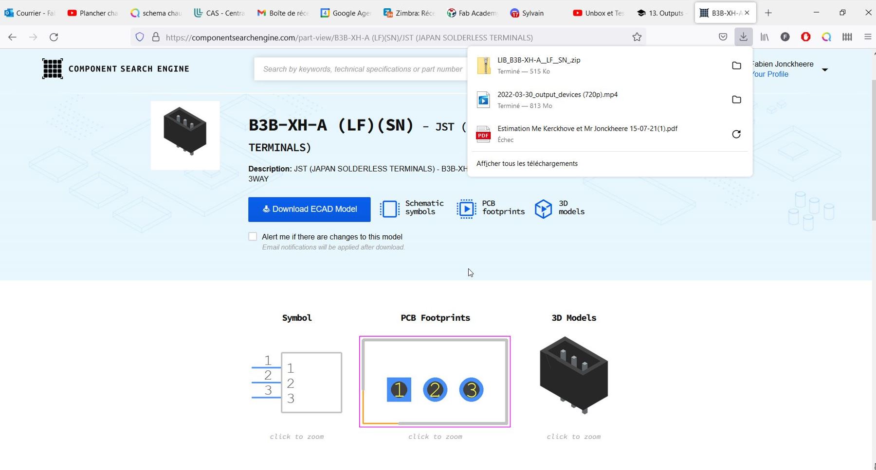
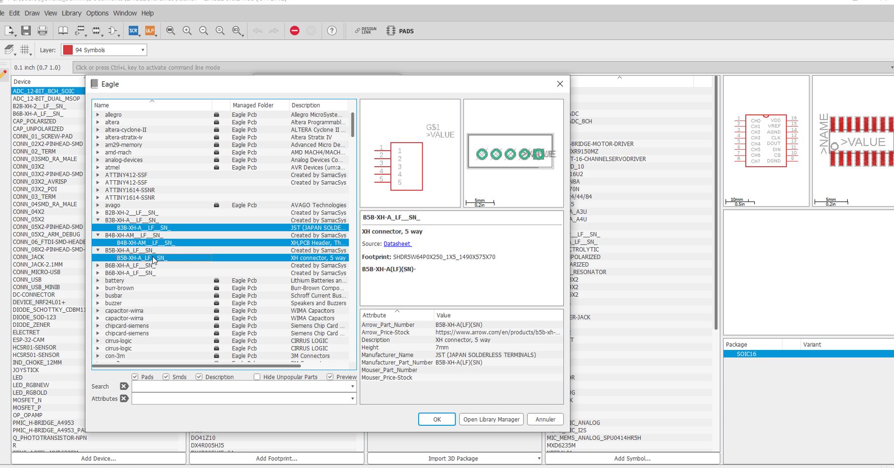
LIBRARIES
You need some material (resitor, capacitor, etc…) and as a lego box, you import a library full of parts usually used for fabacademy projects:
the fab.lbr is available and always updated.
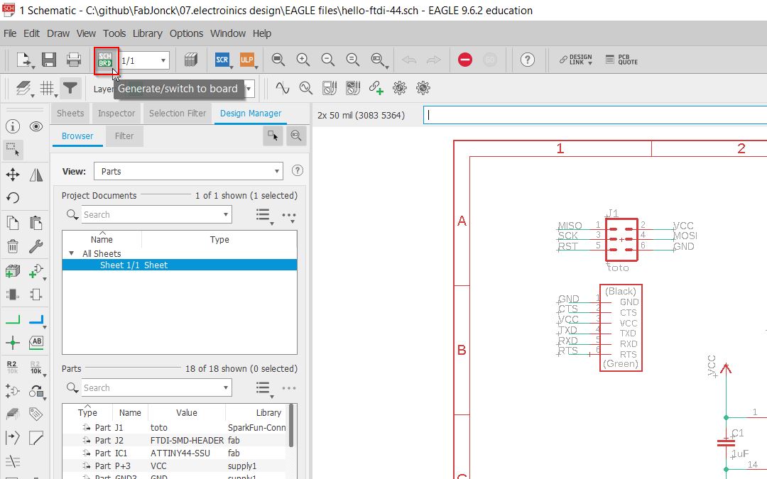
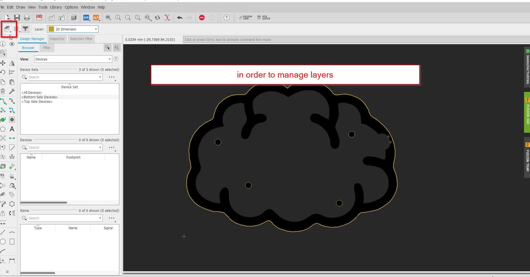
You can switch between the board and the schematic by using the brd/sch button:
I use the command move,rotate to organize a lit bit this whole mess.
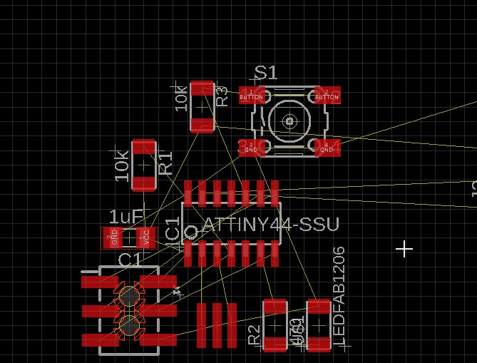
Well, I was a bit lost…

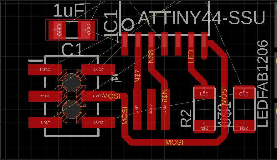
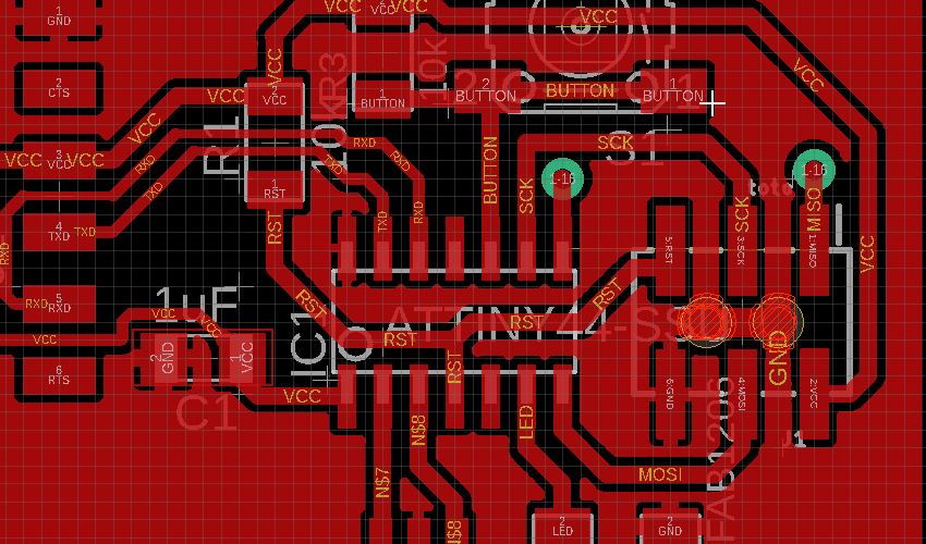
Experimenting, I was trying functions such as route.
My colleague told me to use the DRC, Design Rule checking, bUT I did not know that we have one from Fabacademy.
I will try to find a way to get everything done.
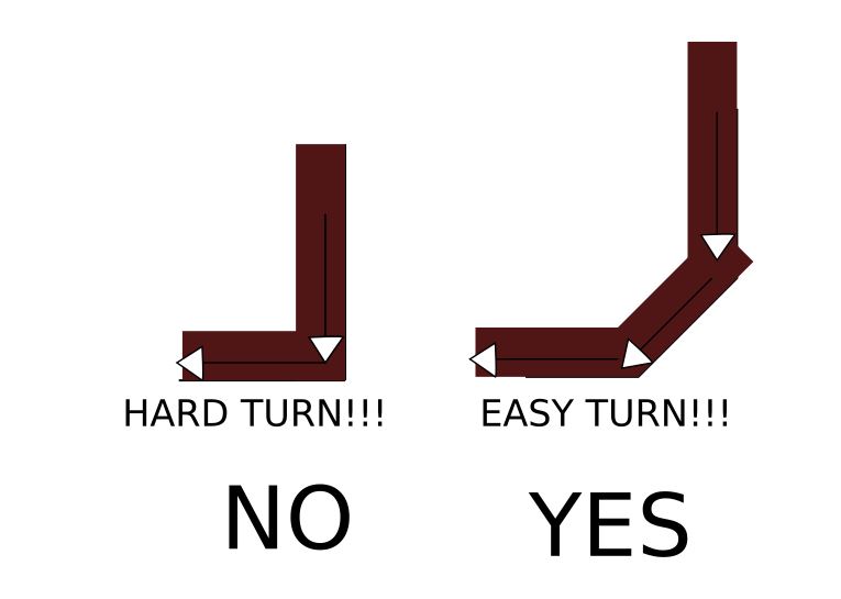
- tip 01 is to avoid any 90° aire wire shifting.
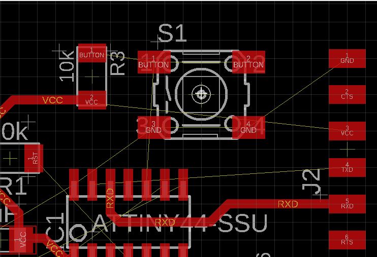
-tip02 make the vcc connection the shortest one.

-tip03 taking care about the Ground at the end.
I was so frustrated because I had a missing connection. Thierry who is in charge of the electronics, gave me a trick. To make two holes and connected them together by the bottom side…
Exporting the two layers (top and bottom.)
We are going to use the cnc LPKF machine, it needs the gerber files.
reminder from wikipedia: The Gerber format is an open, ASCII, vector format for printed circuit board (PCB) designs.[1] It is the de facto standard used by PCB industry software to describe the printed circuit board images: copper layers, solder mask, legend, drill data, etc.
Simply exporting the file.
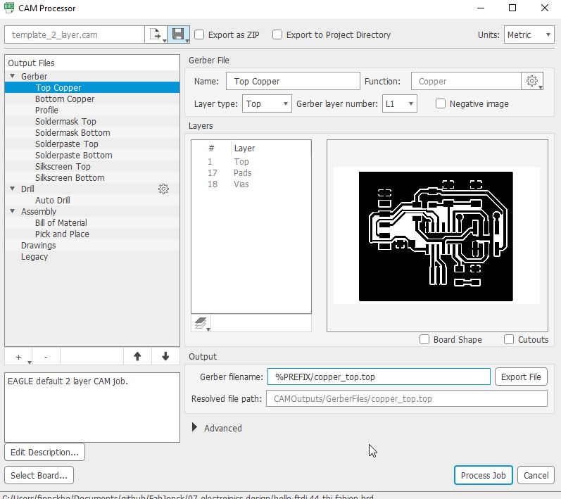 The top copper side.
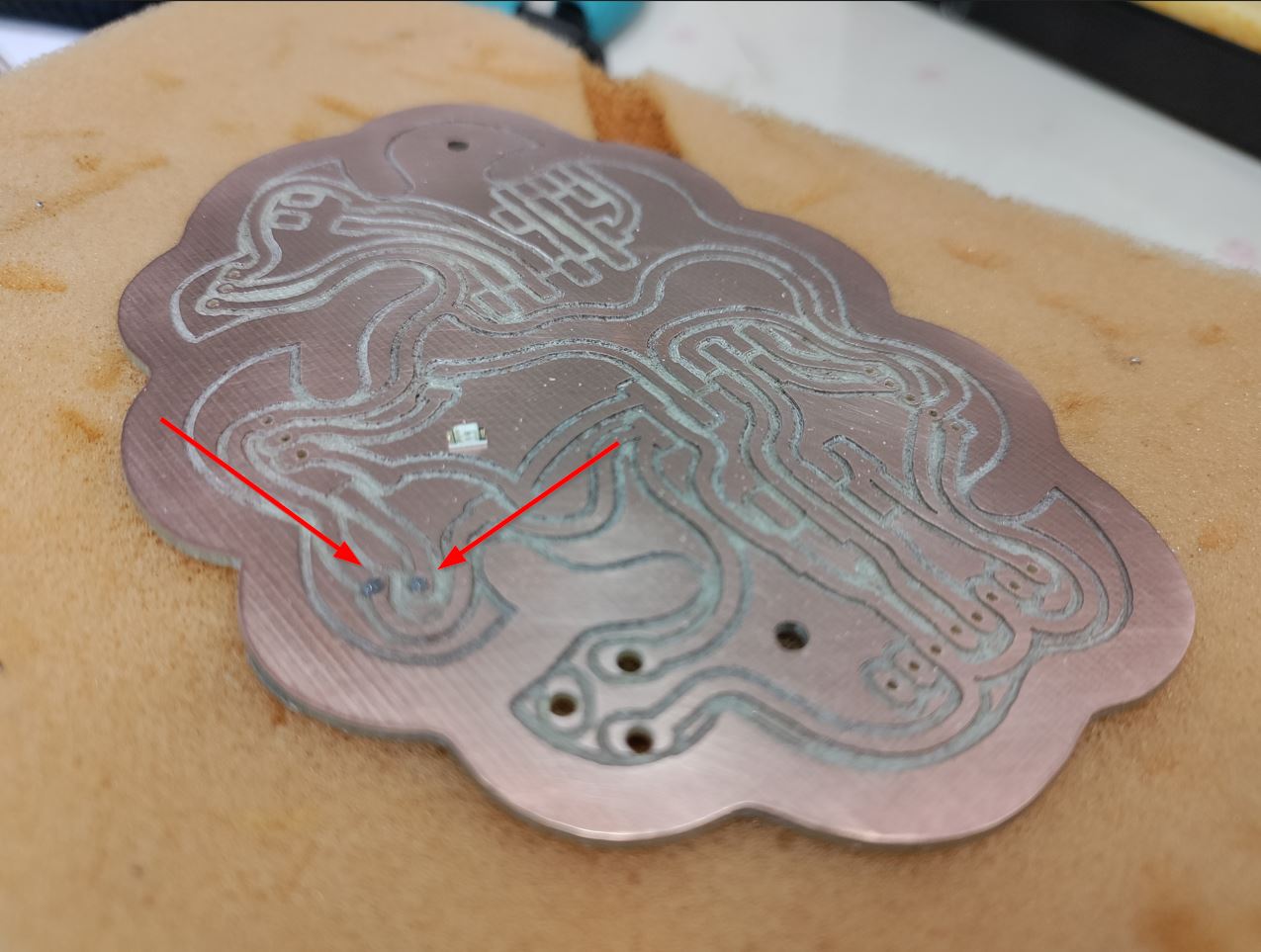
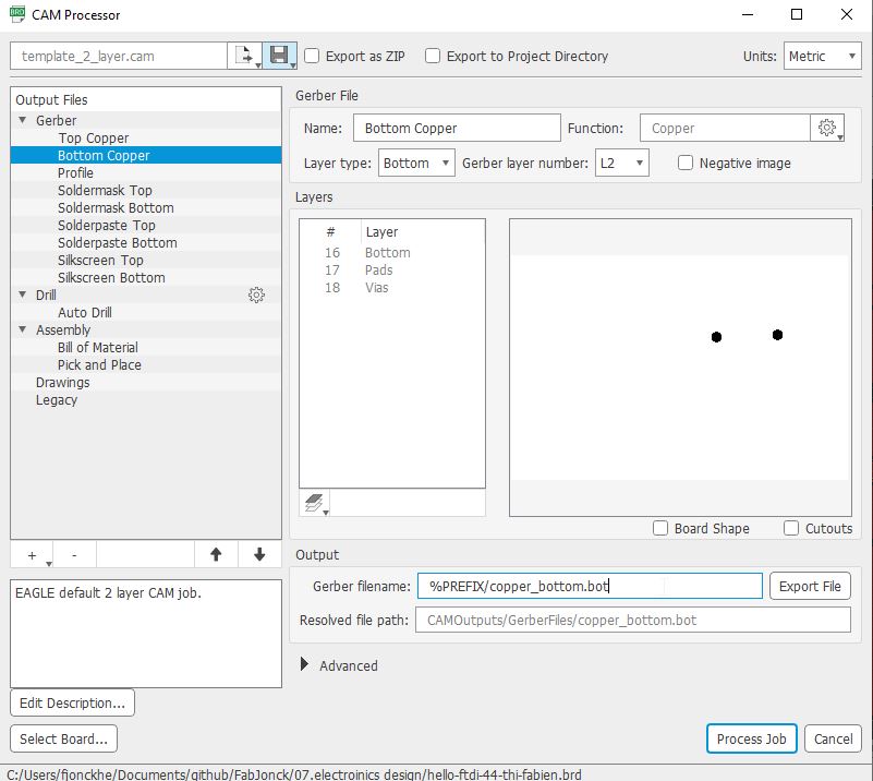 the bottom copper: two holes to reach to MISO pin.
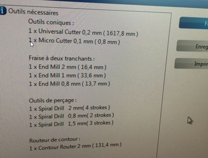
Sending the files to the LPKF milling machine.
We use 35microns FR4 board.
More informations about the settings on the 5th week : - ELECTRONICS PRODUCTION
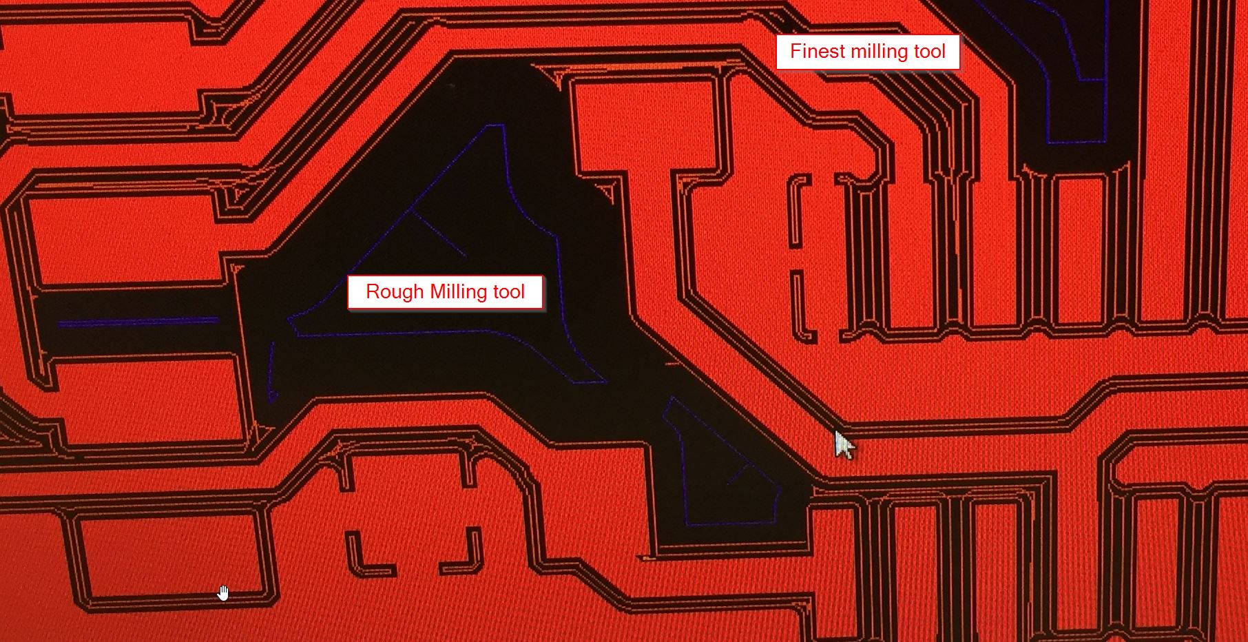
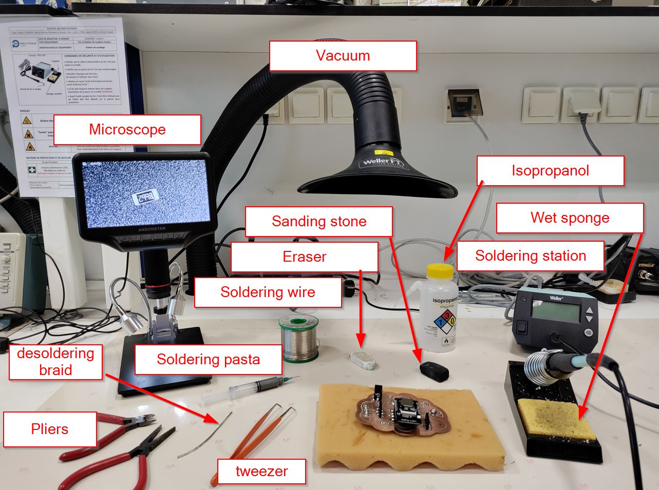
THe LPKF machine provides us the proper tools:
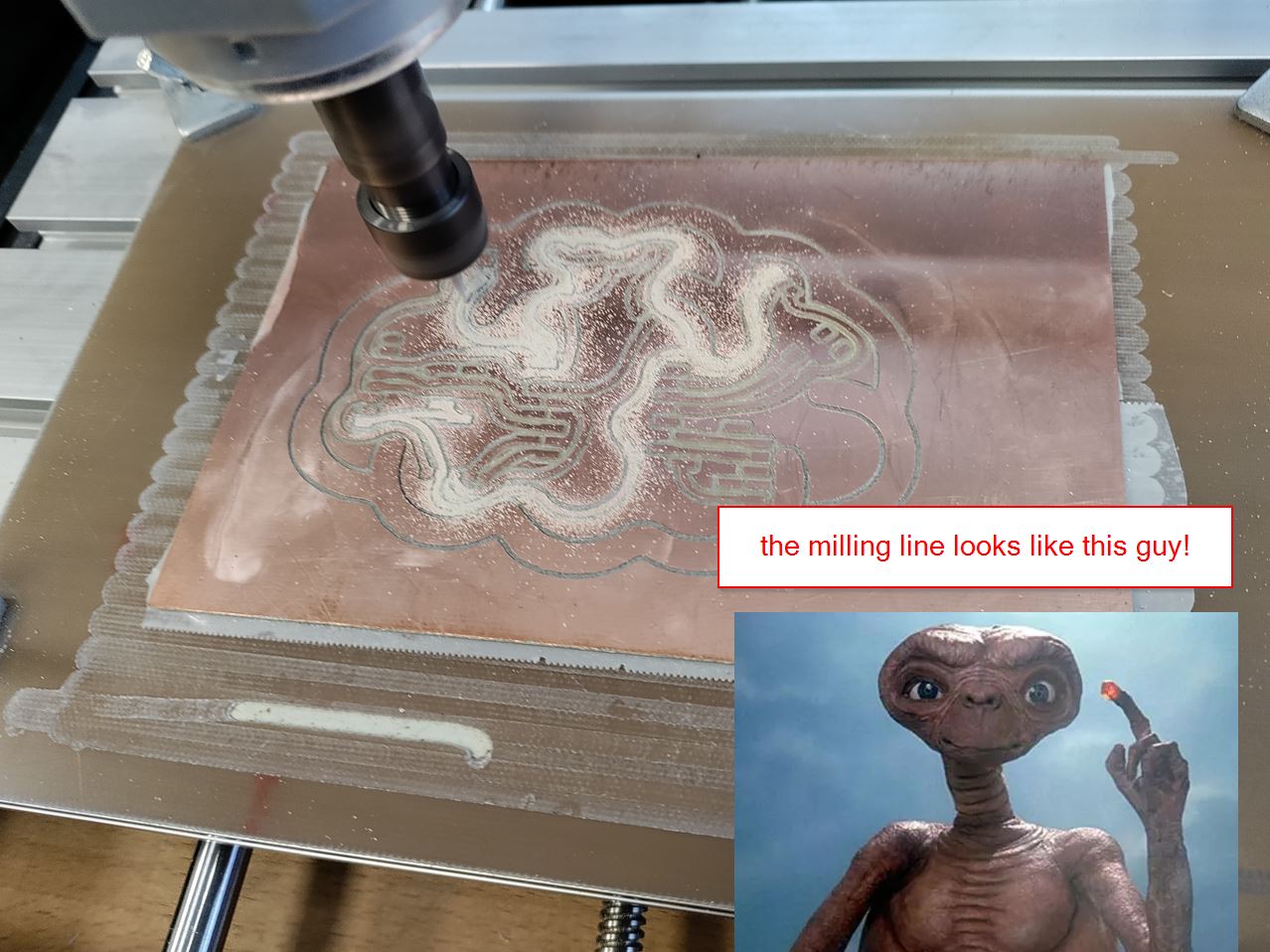
This is the milling paths on the LPKF machine
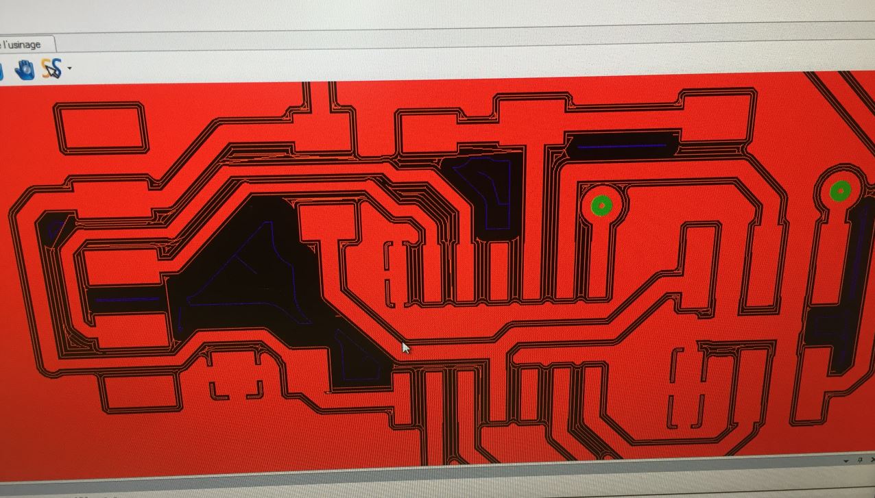
ZOOM
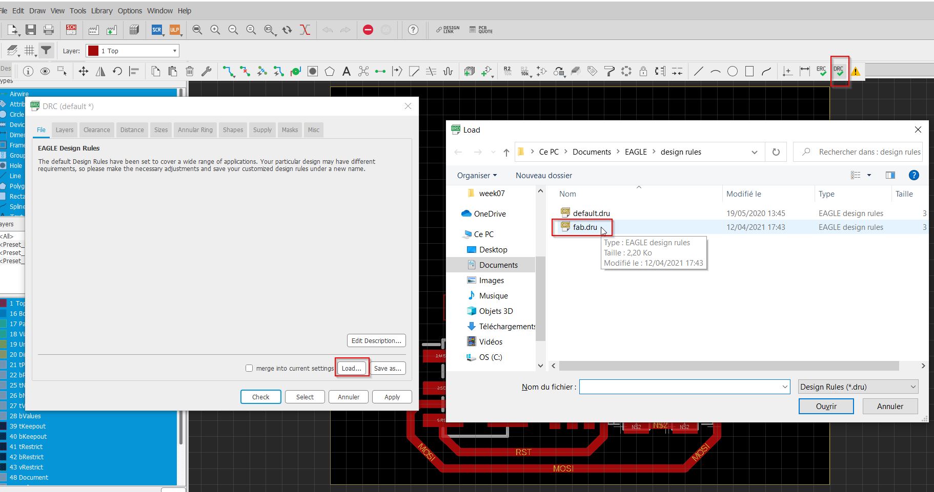
Lately I installed the DRC from fabacademy!!
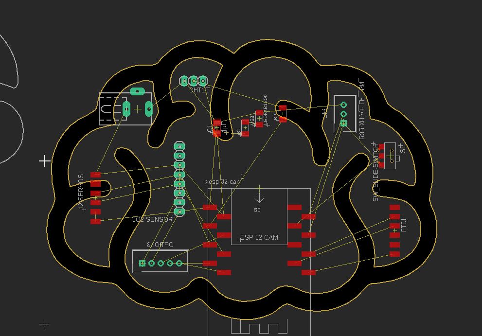
RatsNest
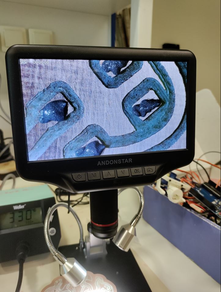
pasta stings
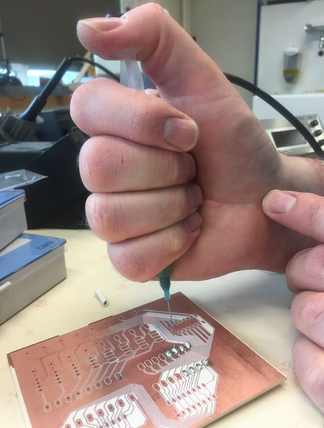
The sting is very precise but need dexterity.
 We made a try by brazing with brazing pasta(40% lead /60% stain) There is some resin called flow which prepares the soldering by cleaning at 150°c.
Economical Convection Oven for SMT Prototyping: LPKF ProtoFlow E
The LPKF ProtoFlow E convection oven offers reliable reflow soldering across the entire PCB, including lead-free solder materials.
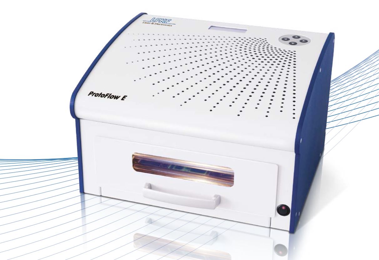
Its temperature limit isn’t reached until 320 °C (608 °F). The reflow oven with a max. material size of 160 mm x 200 mm (6.3” x 8”) is perfectly matched to the LPKF ProtoPrint E. A drawer window offers a view of the lighted process chamber, and the USB connection allows the LPKF ProtoFlow E to also be programmed from a PC for faster and easier process analysis.
Fully convectional Lead-free reflow process Temperature up to 320 °C Multi-zone temperature/time profiles USB connectivity
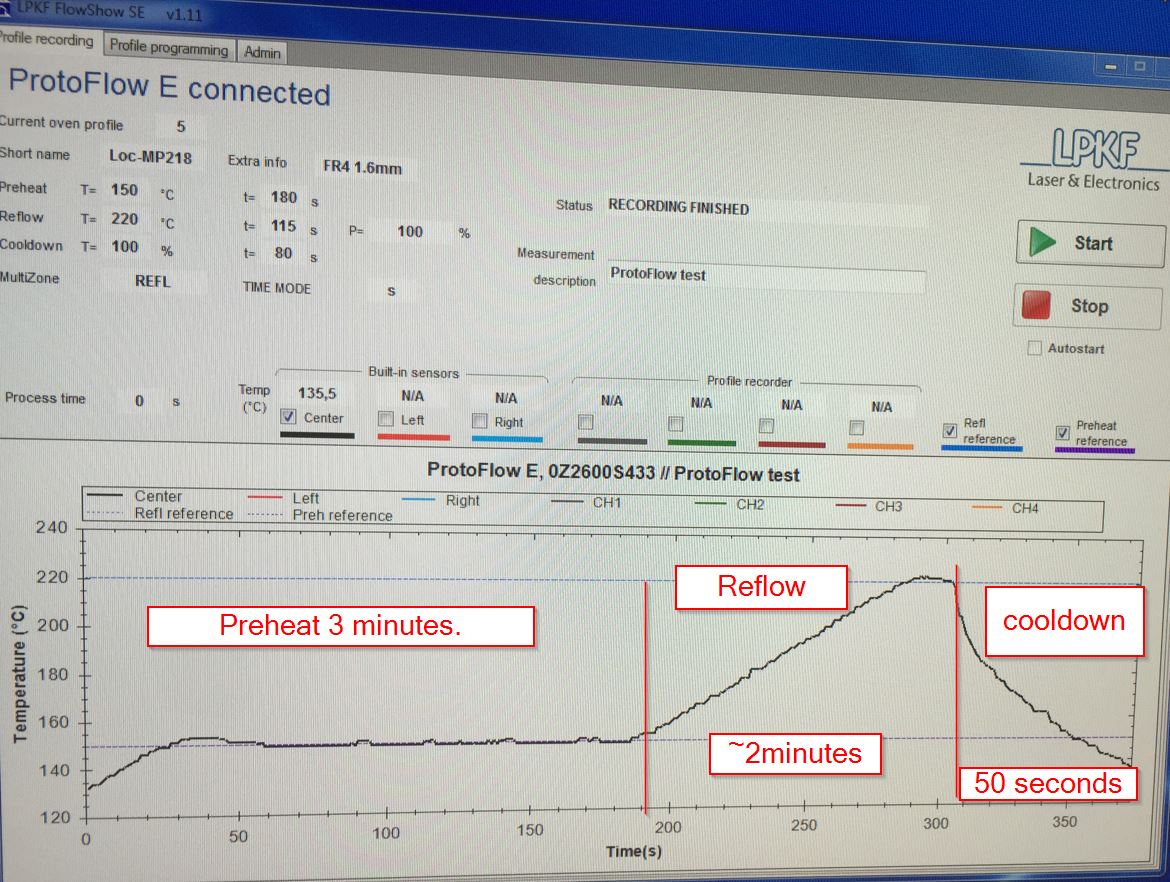
It increases gently 1 degree/second. At 183°C, the state is becoming from solid to doughty. At 220°c, the reflow is beginning, by decreasing 1°c/second.
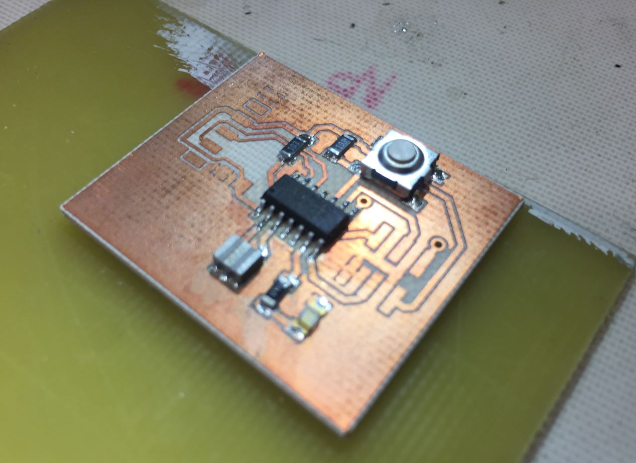
Ting!!! This is READY!
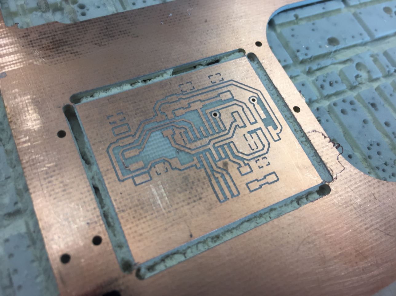
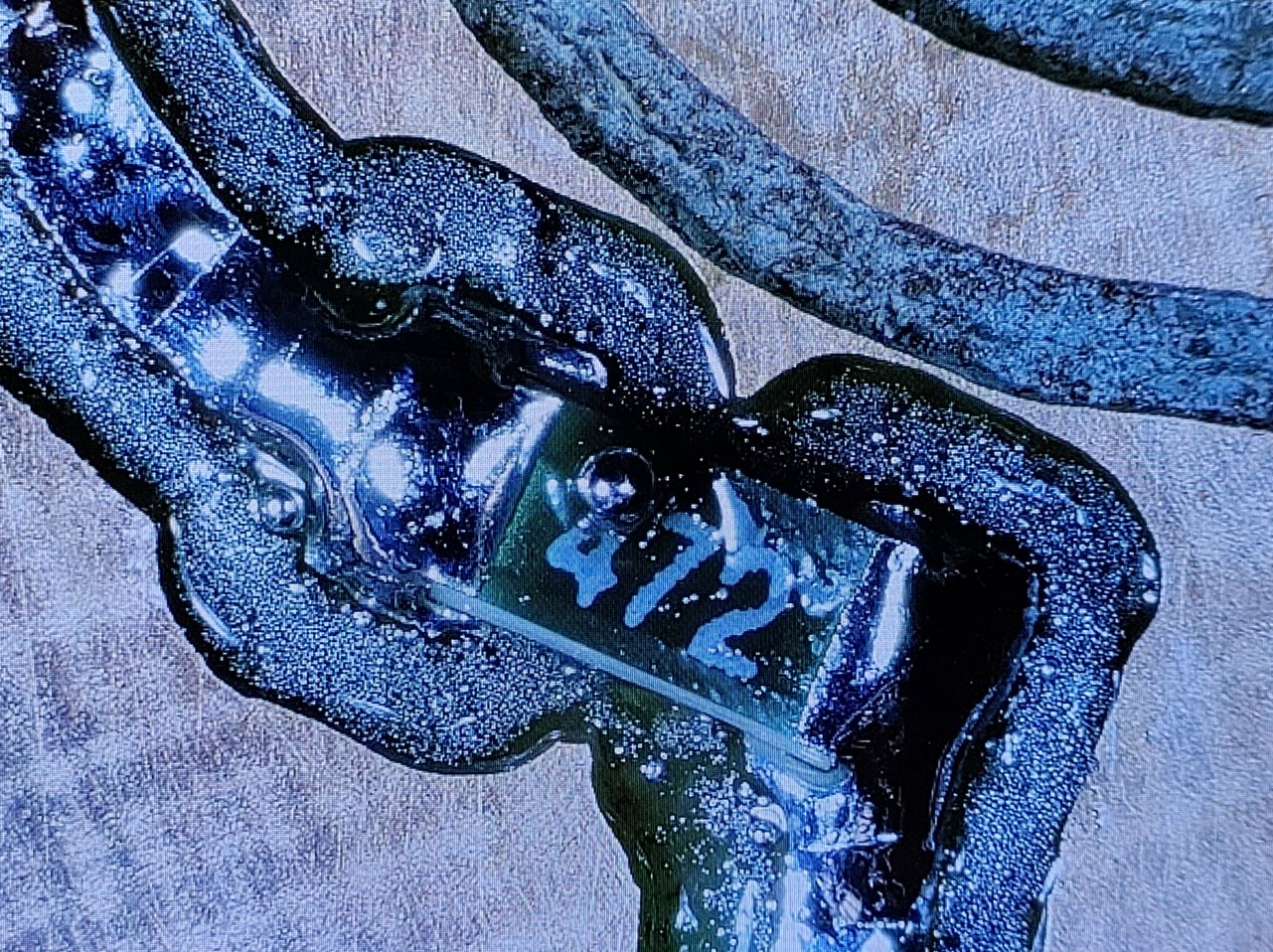
Zoom on the board
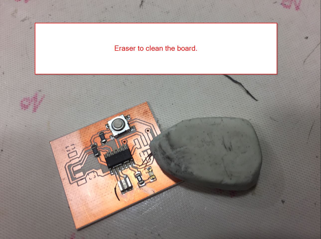
Erasing
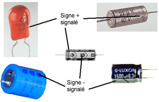
Well, It is time to solder the 1uF capacitor. You need to know the polarity:
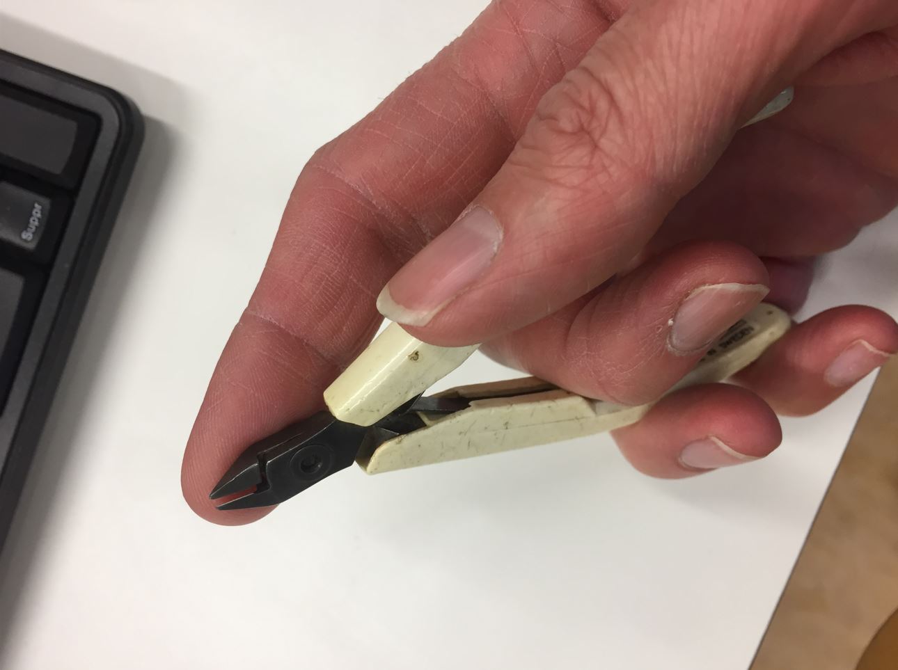
How to put properly your fingers on a wire cutter!
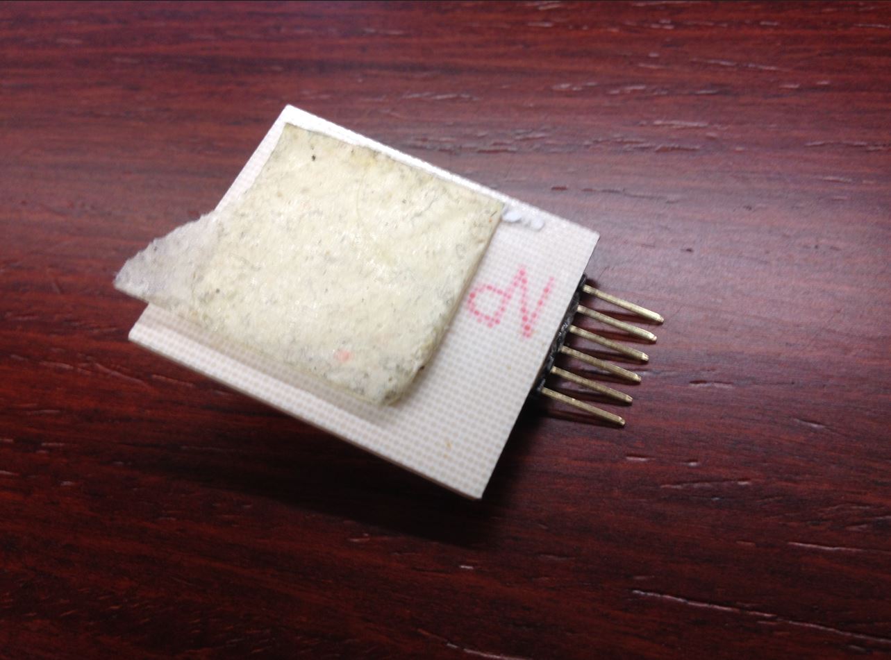
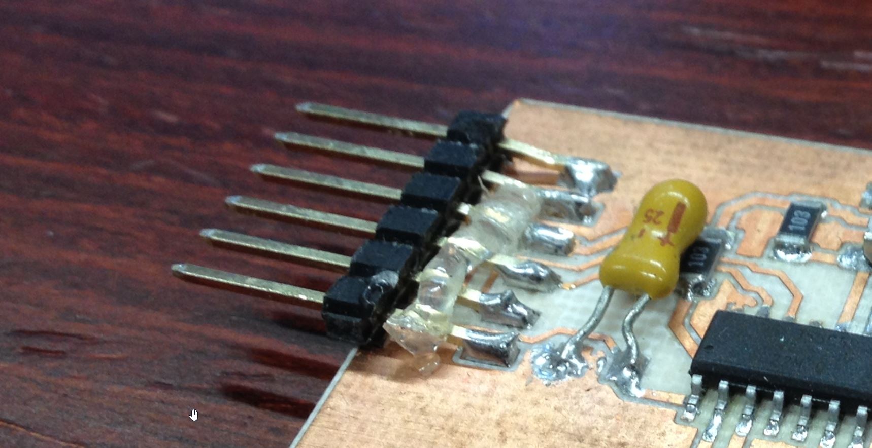
How to connect Miso from the back board by using the holes.
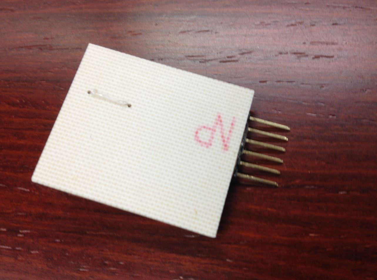
I just soledered a wire and stuck a strong double sided foam tape.
I cut properly my capacitor and added to the board:
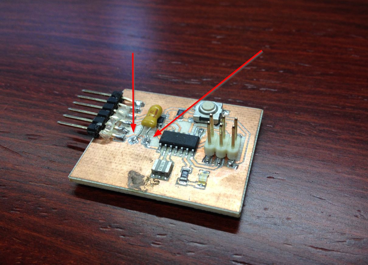
TIP My colleague also told me to use a glue gun to
I am checking the continuity, everything seems ok!!
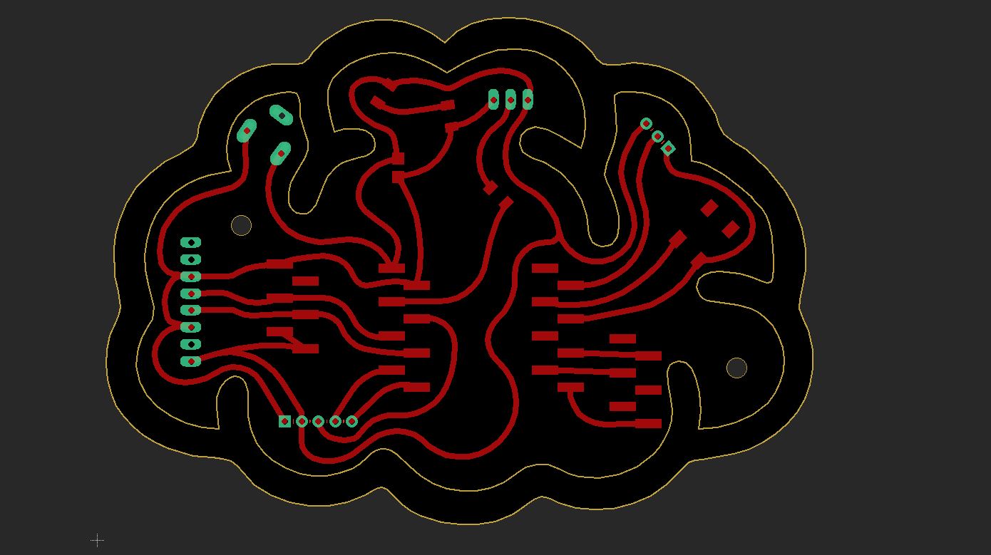
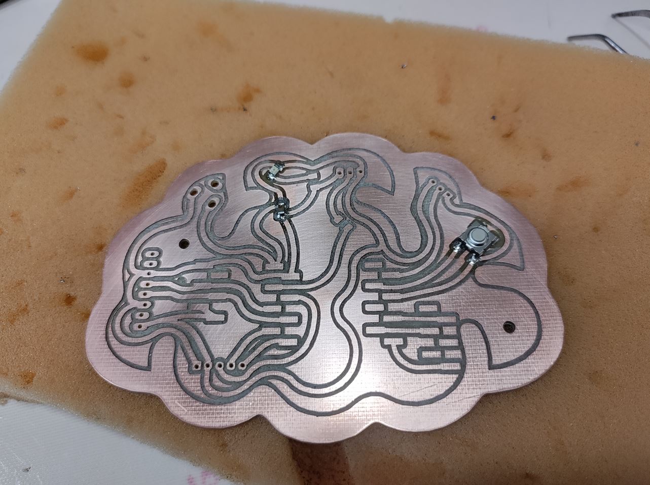
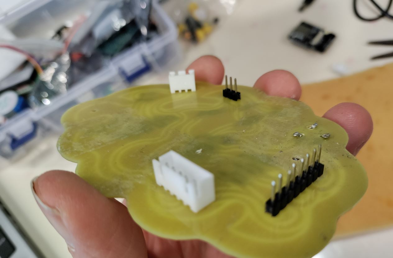
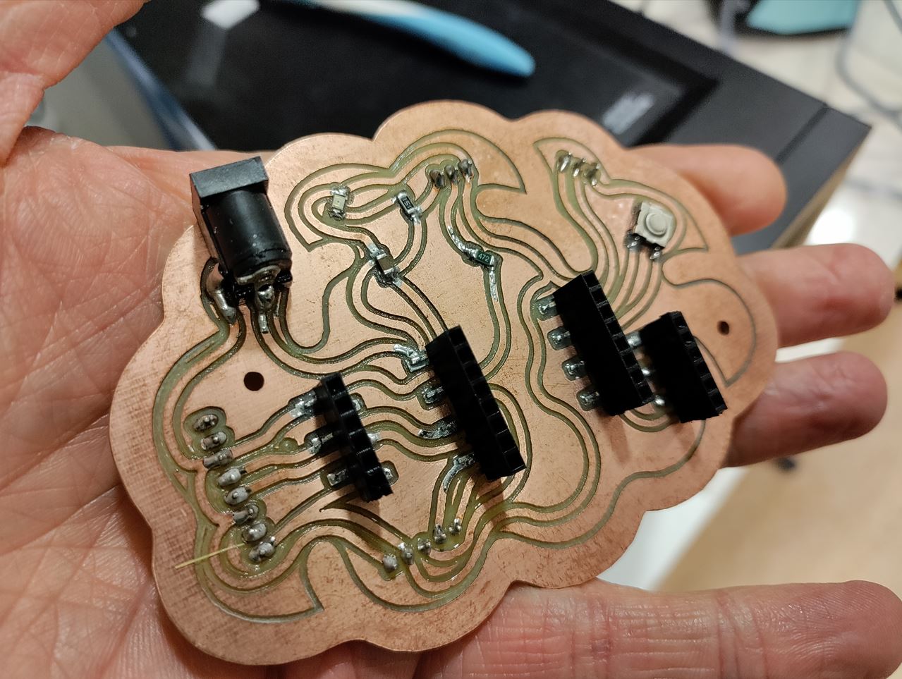
Brain board.
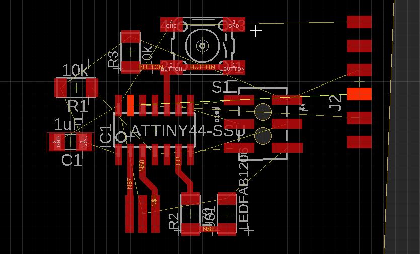
Alternatively, I was starting my final project board.
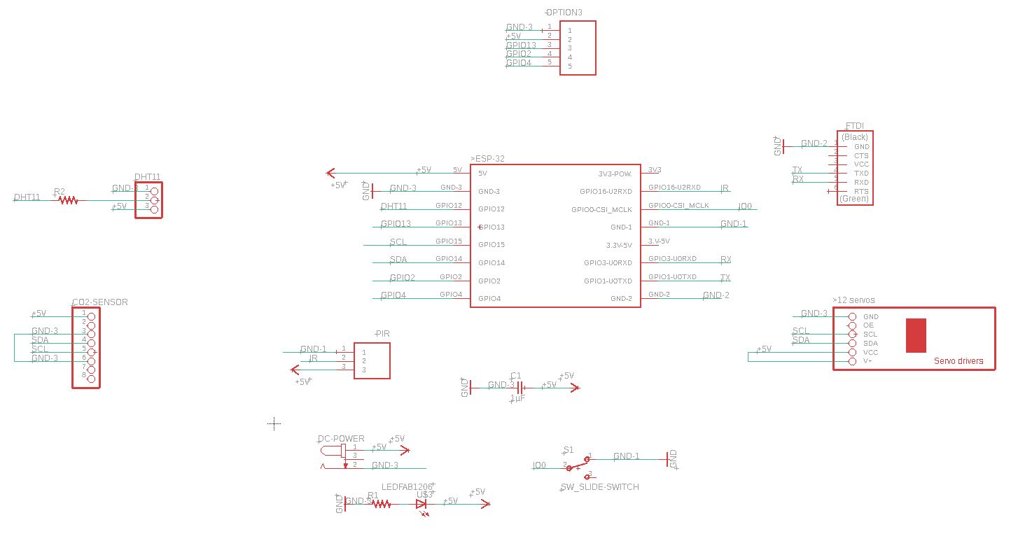
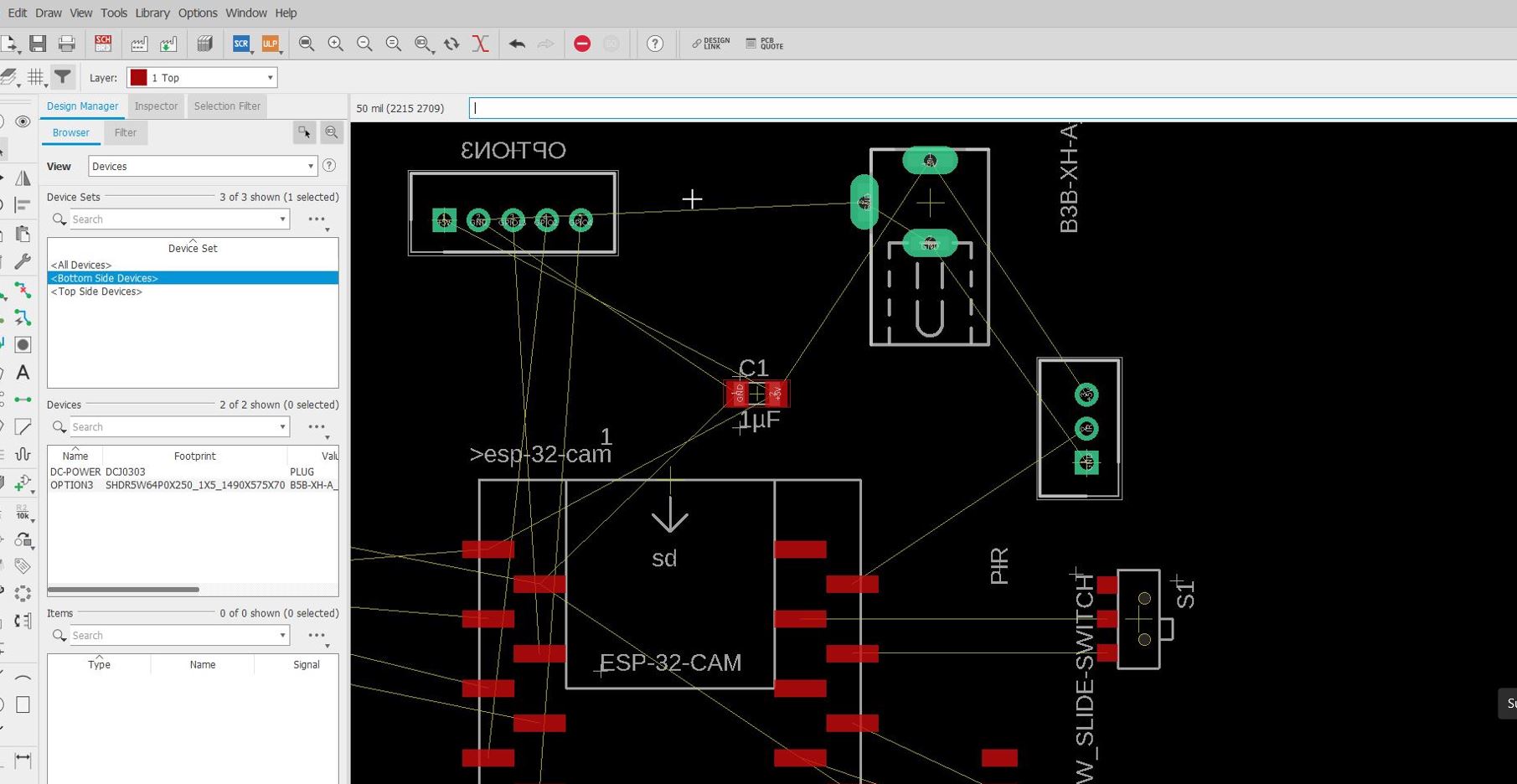
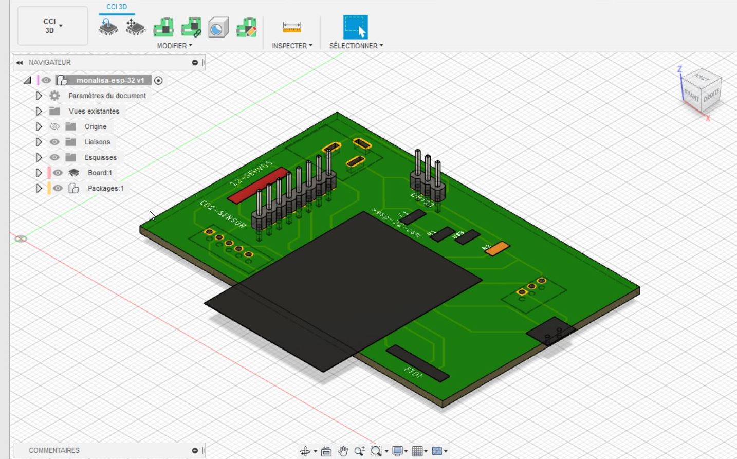
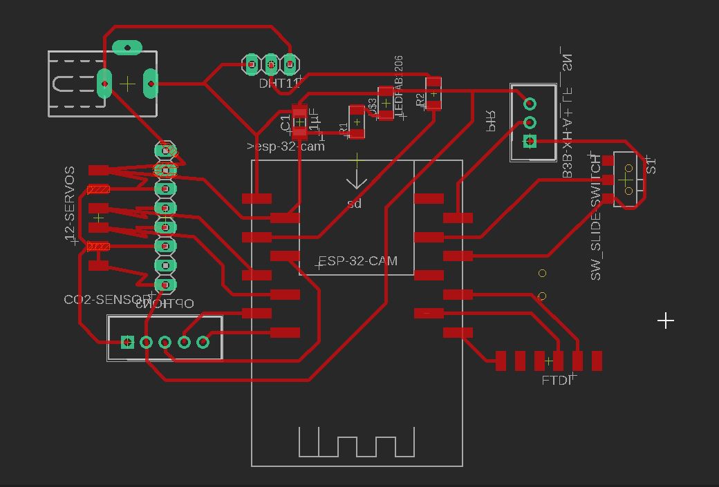
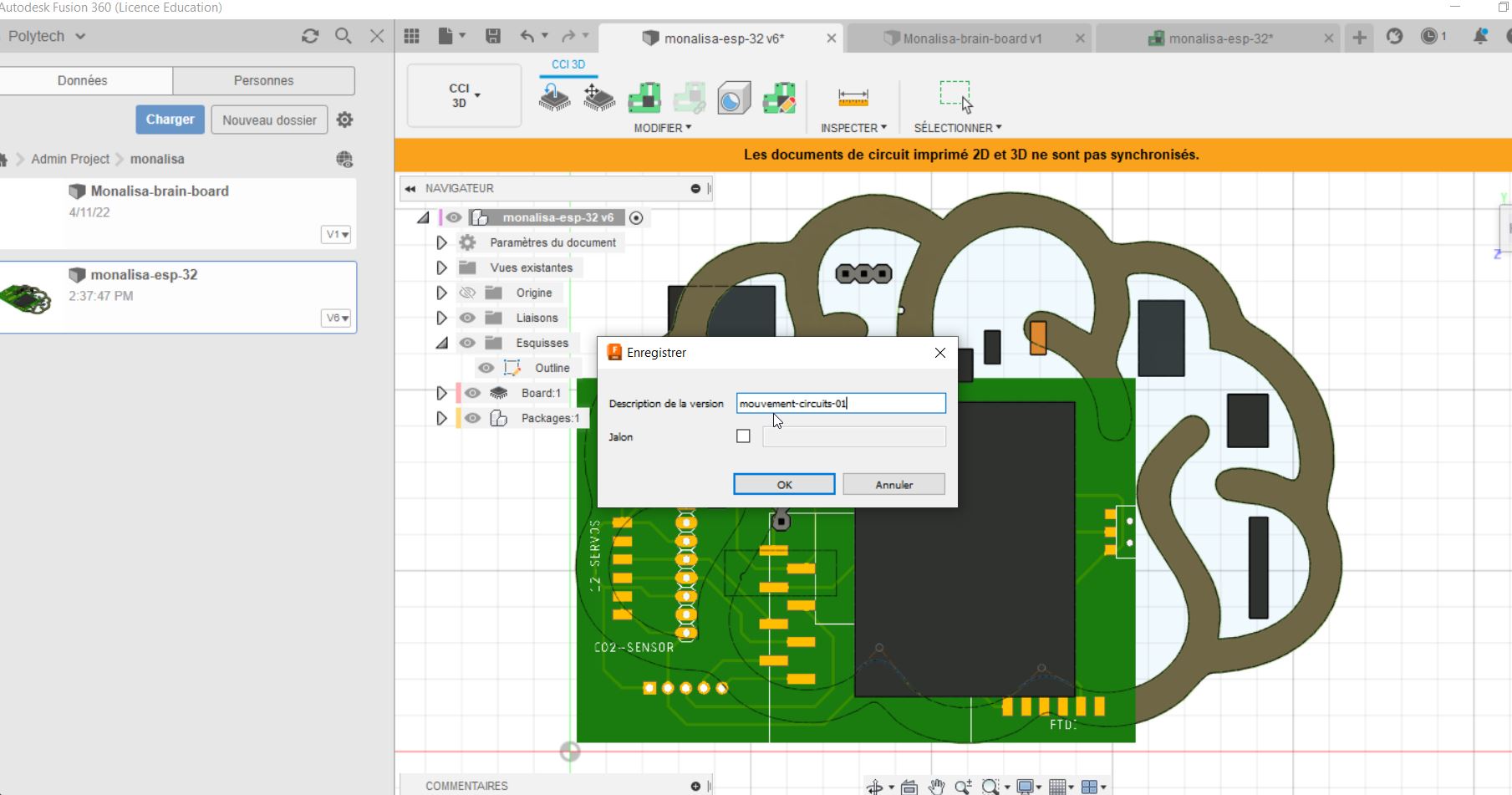
I have thought again and updated some parts, but there were still DRC problems.
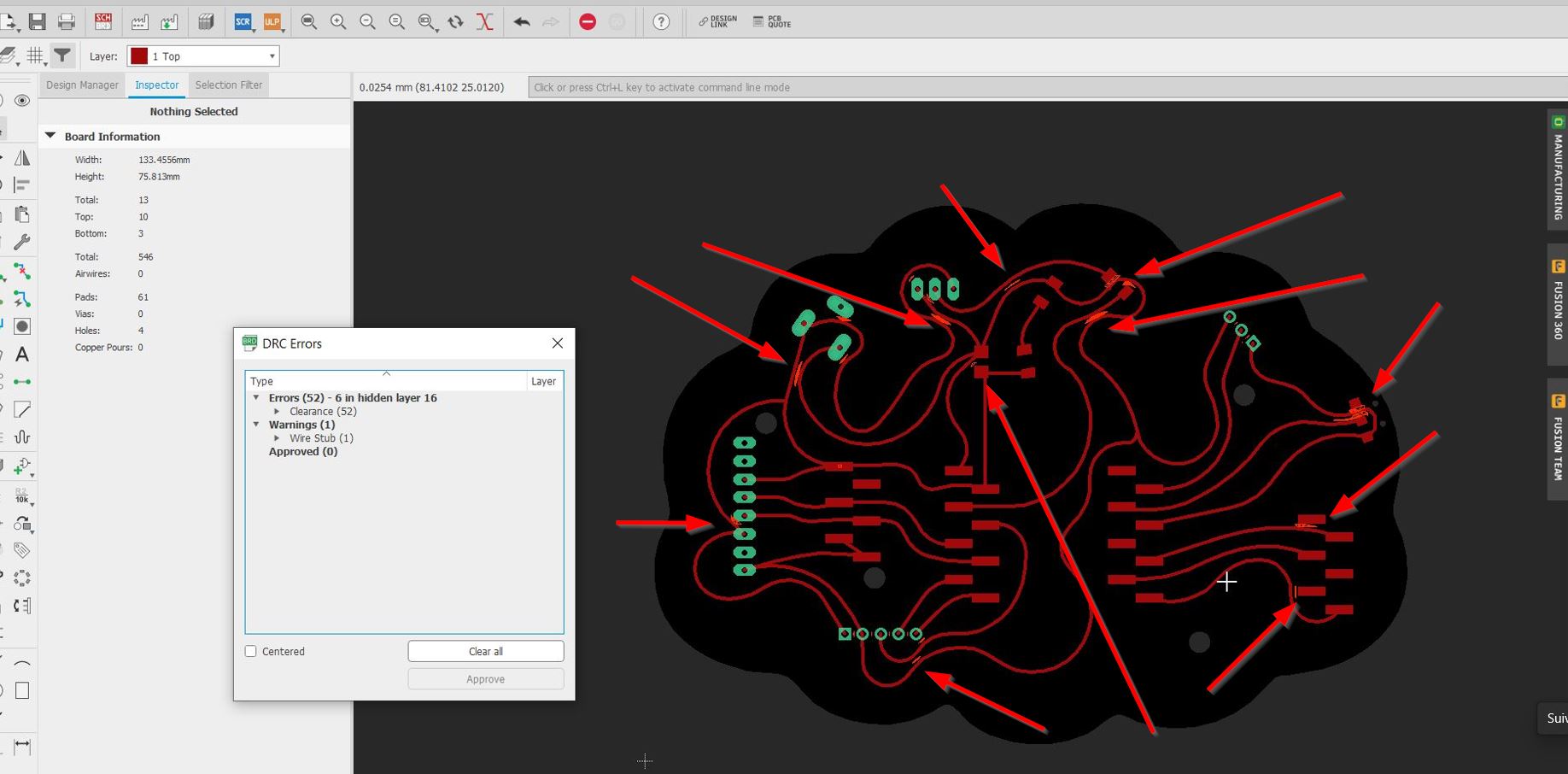
I was not also satisfied about the Esp 32 programming switch, I was thinking to put a button.
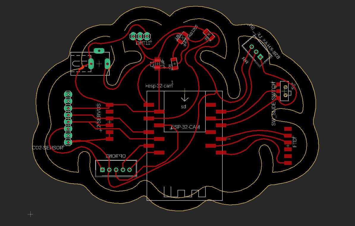
My colleague Sylvain had a look to my board and told me that the Design Rules Check was not appropriated. The traces and the spaces between each other should be bigger (0.8mm) I opende the DRC and he advised me to change the mil 1Mils = 0.025mm . I changed 16 into 35 mils. (0.889mm)
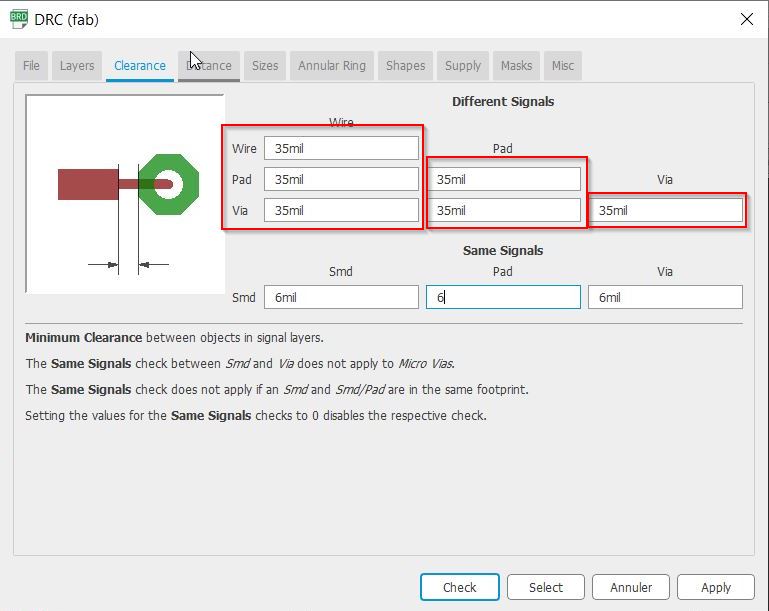
![]()
The DHT 11 and the Fab LED have changed their place. FTDI have moved to the center.
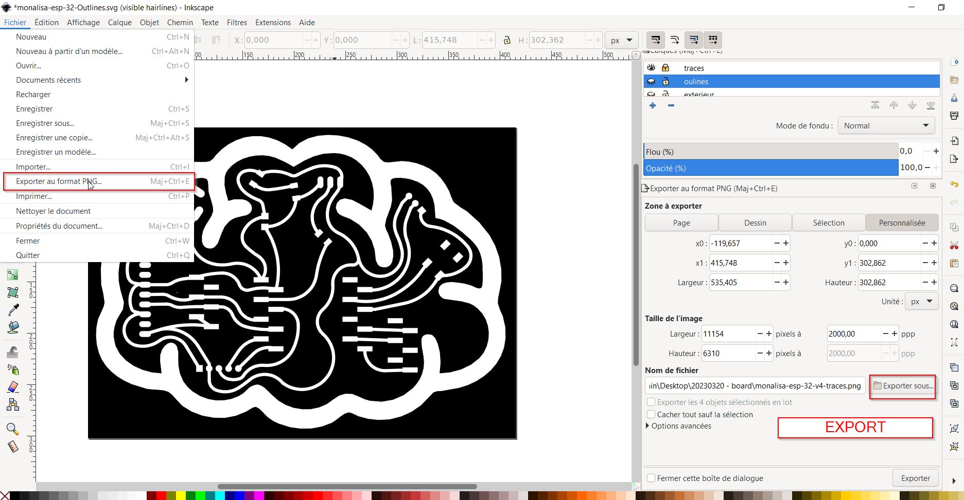
Time to print as a pdf file (black option ticked)
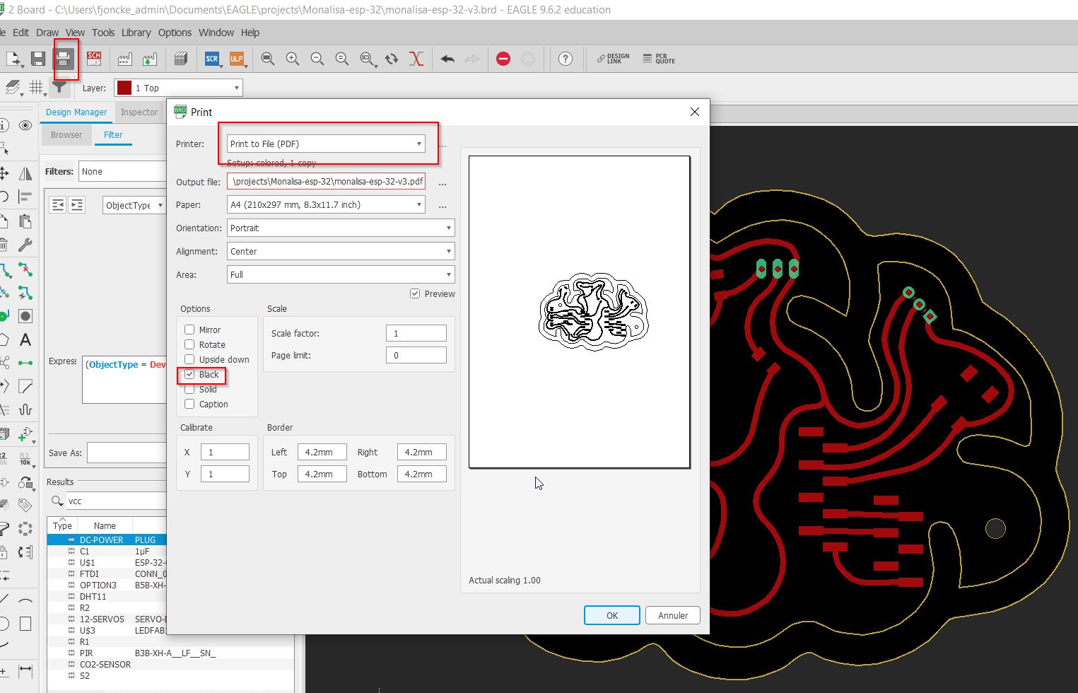
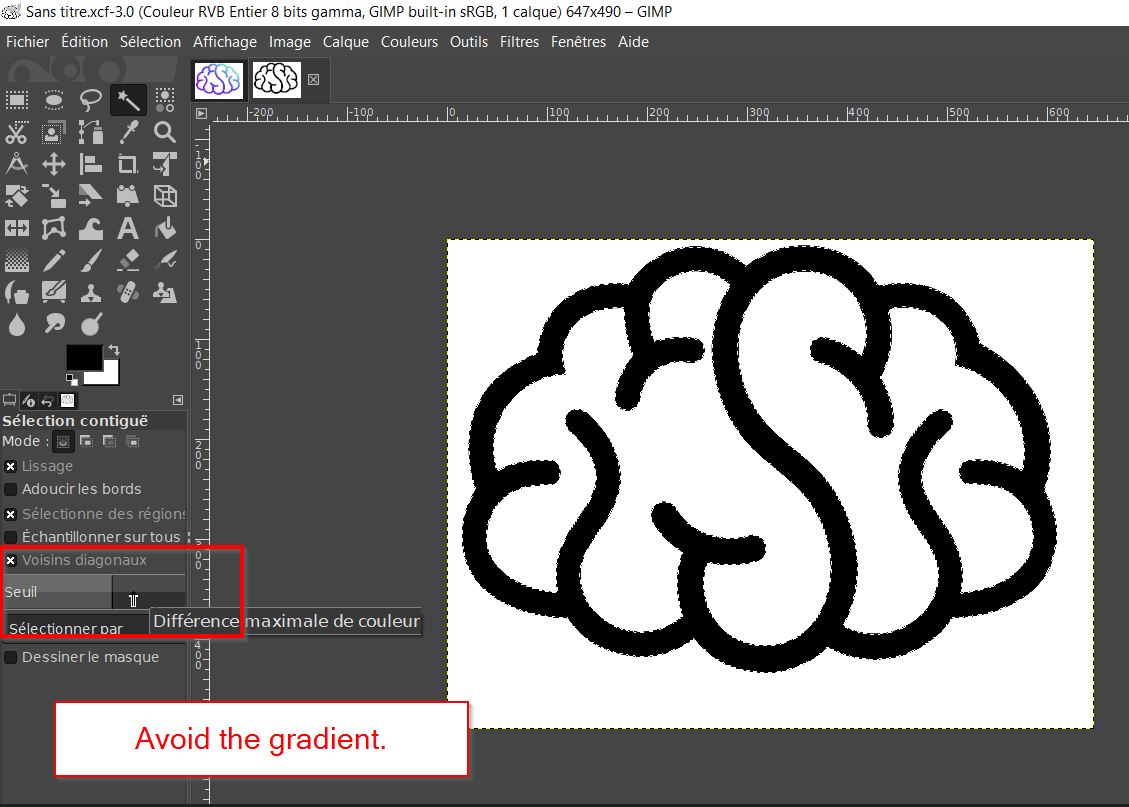
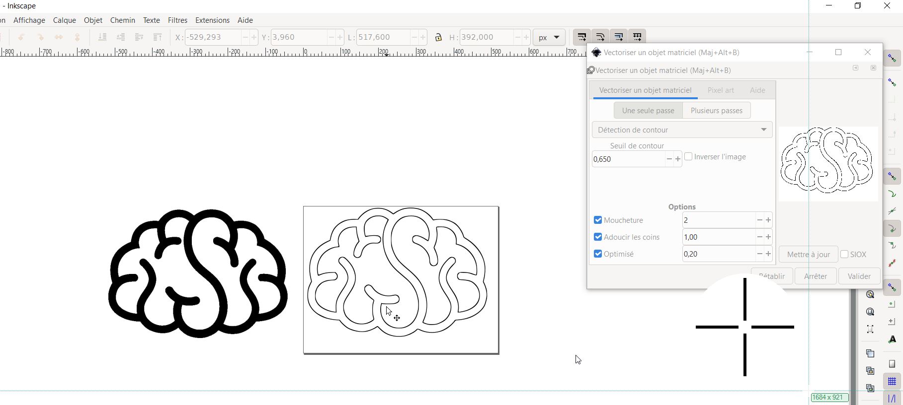
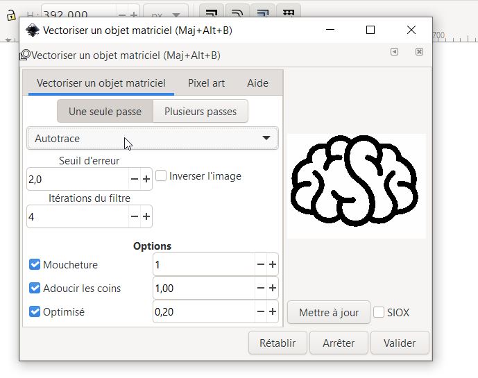
Open inkscape to get the traces and outlines files.
REMEMBER: WHITE IS WHAT I KEEP AND BLACK IS WHAT I REMOVE.
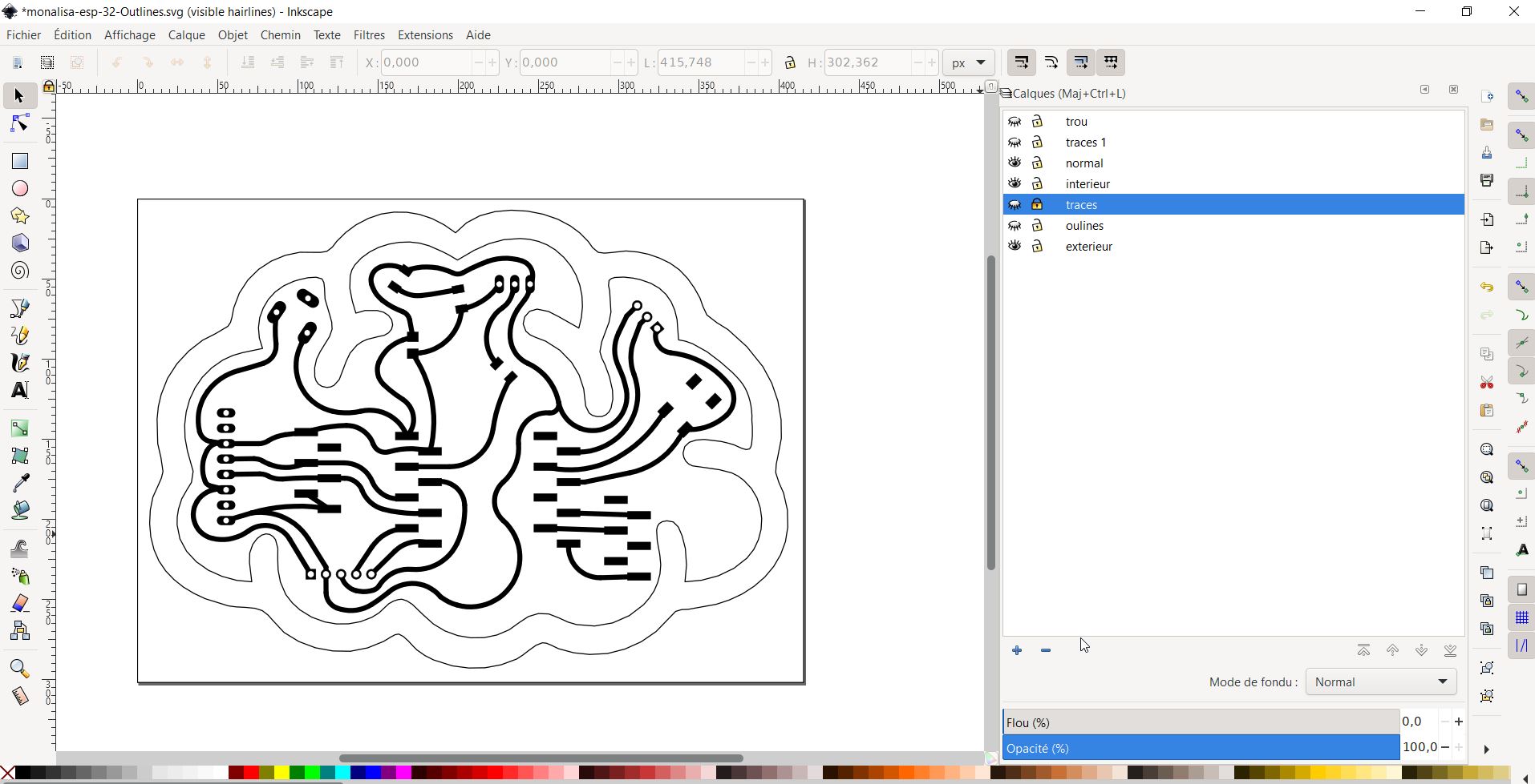
TIP: CTRL + 5 gives you the vectors only. It is convinient when you have thin curves ( usually lasercutting has 0.1 or 0.2 even 0.001 lines) it is impossible to see something. Be carreful, press CRTL+5
I have made layers to be organized. “normal” is all curves.
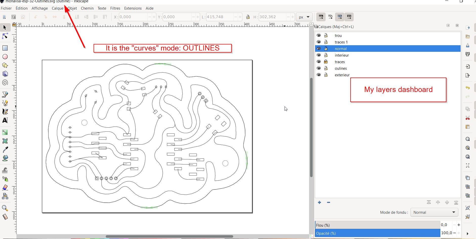
Press + to get a new layer, I have created “outlines” and “traces” By using the color panel, Black area and white have been designed.
I have right clicked one the desired curves and use the move to layer command.
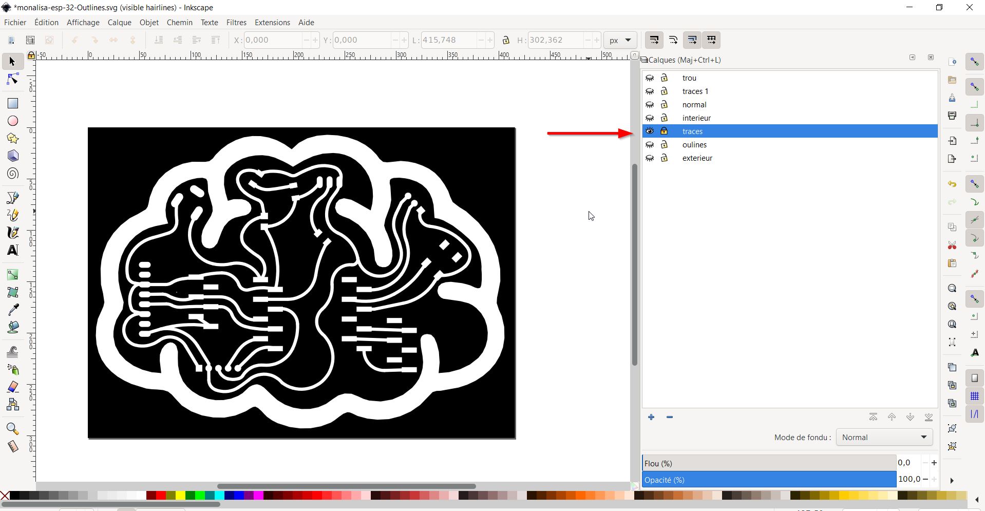
Here you have the traces:
And if you hide traces and make the outlines visible:
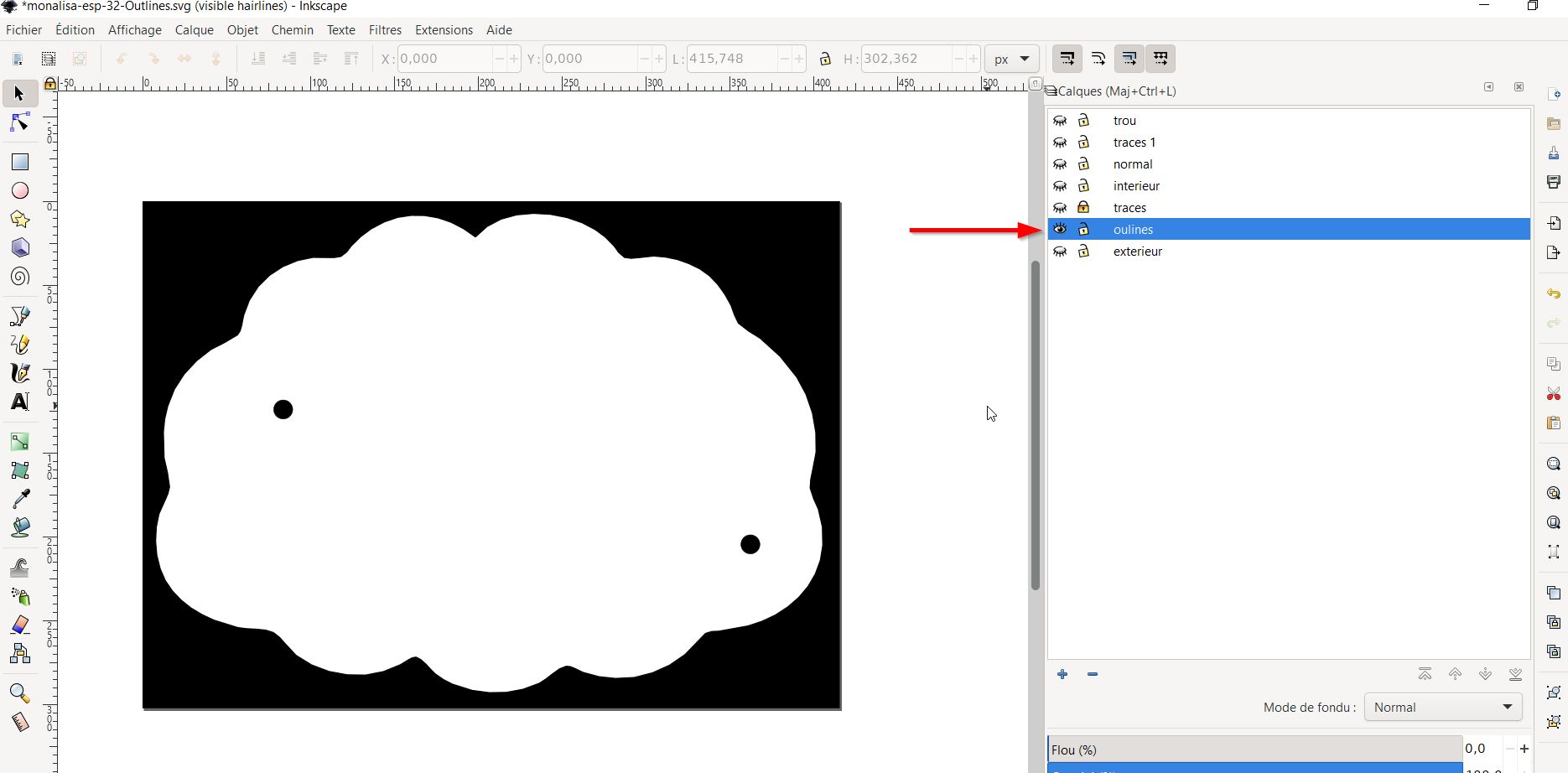
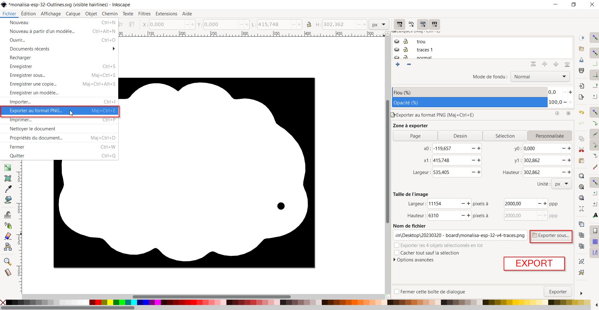
you get the holes and outer outlines and ready for exporting png files.
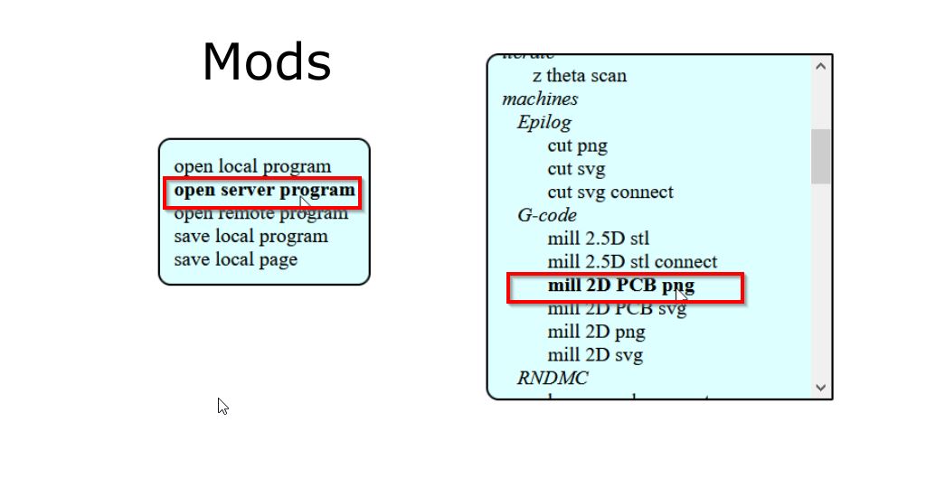
MODS
Explanations about mods
I have opened the previsous traces png
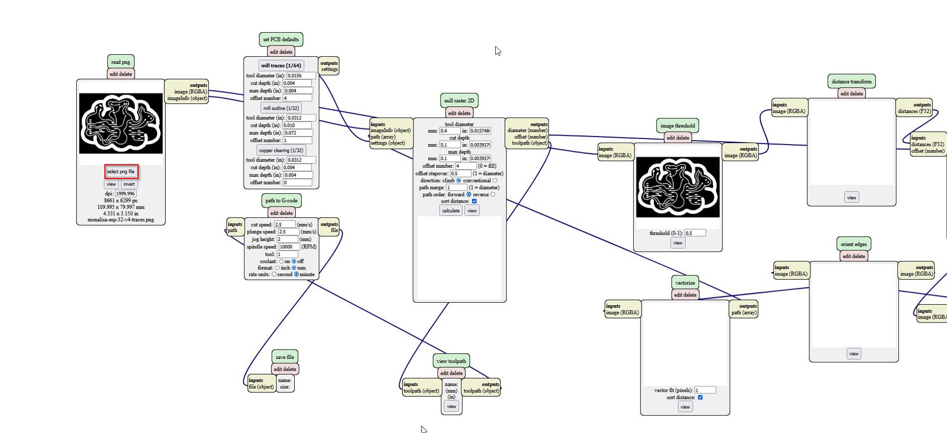
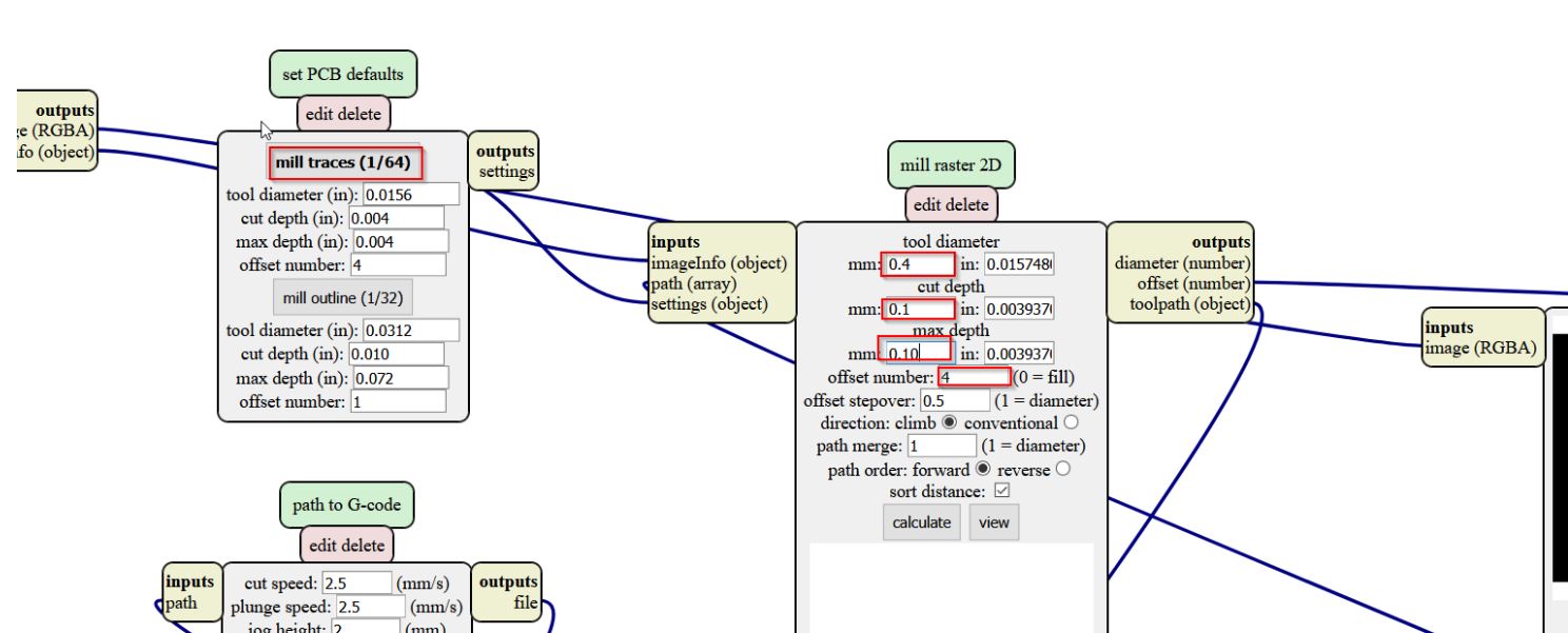
==> calculating. ==> check you routing paths!!
You do the same process for the outlines png file.
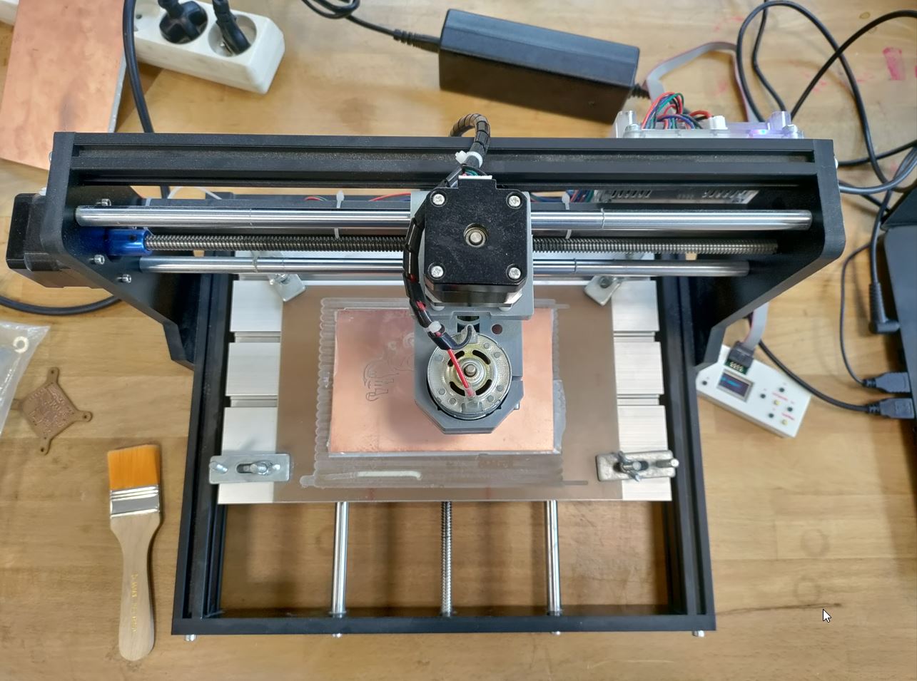
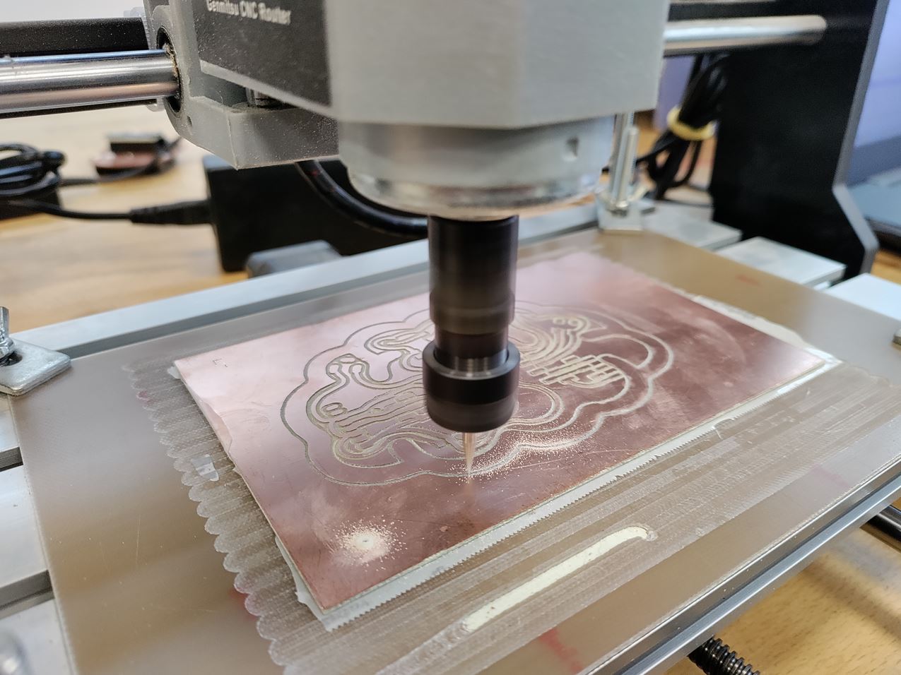
Sainsmart CNC machine
SainSmart Genmitsu CNC Router 3018-PRO. website
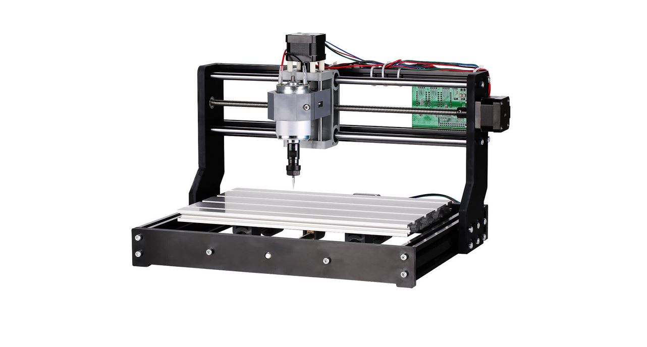
| SPECIFICATIONS | CNC router |
|---|---|
| Effective Engraving Area: | 300 x 180 x 45 mm(11.8 x 7.1 x 1.8”) |
| Frame Size: | 400 x 330 x 240 mm(15.7 x 13.0 x 9.4”) |
| Frame Material: | Aluminum |
| Axis Bracket Material: | PF |
| Z-Axis Component Material: | Nylon |
| Spindle: | 775 motor, 12V, 3000 RPM; 24V, 7000 RPM; 36V, 9000 RPM |
| Rated Power: | 60W; Maximum Power: 120W |
| Step Motor: | 1.3 A, 12V, 0.25 Nm torque (2.2 in lb) |
| Drill Bits: | Tip 0.1 mm, 20 degrees, Diameter 3.175 mm |
| Supported OS: | Windows XP, Windows 7, Windows 8, Windows 10, Linux, Mac OS |
| Software: | Grbl control(Candle) |
| Power Supply: | 24V/4A |
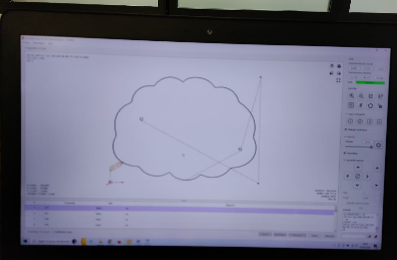
You can get the gerbercontrol software on this link to control your cnc router.
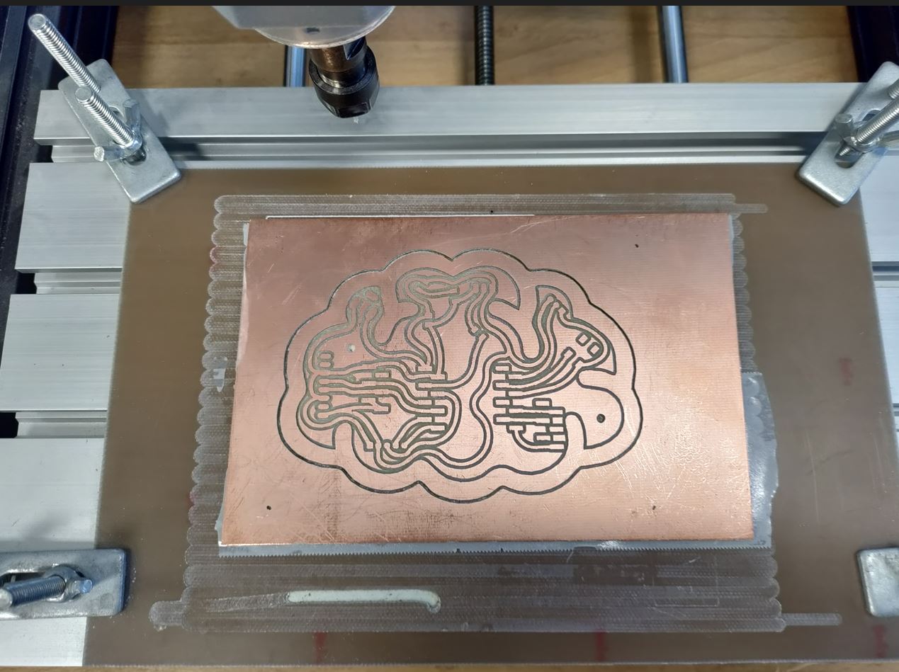
First thing it is to measure your board dimensions (almost 105x75mm) and find a FR4 stock (35 microns of copper)
The “martyr” ( find in english!) board has been milled to get a parallel plane according to the tool. I have sticked the board by using double side tape and it took place at the center of the operating system.
A piece of 150x150mm was my stock.
Now the goal is to check if the tolerance is good enough for milling.
First we turn on the spindle speed at 10000 tr/min.
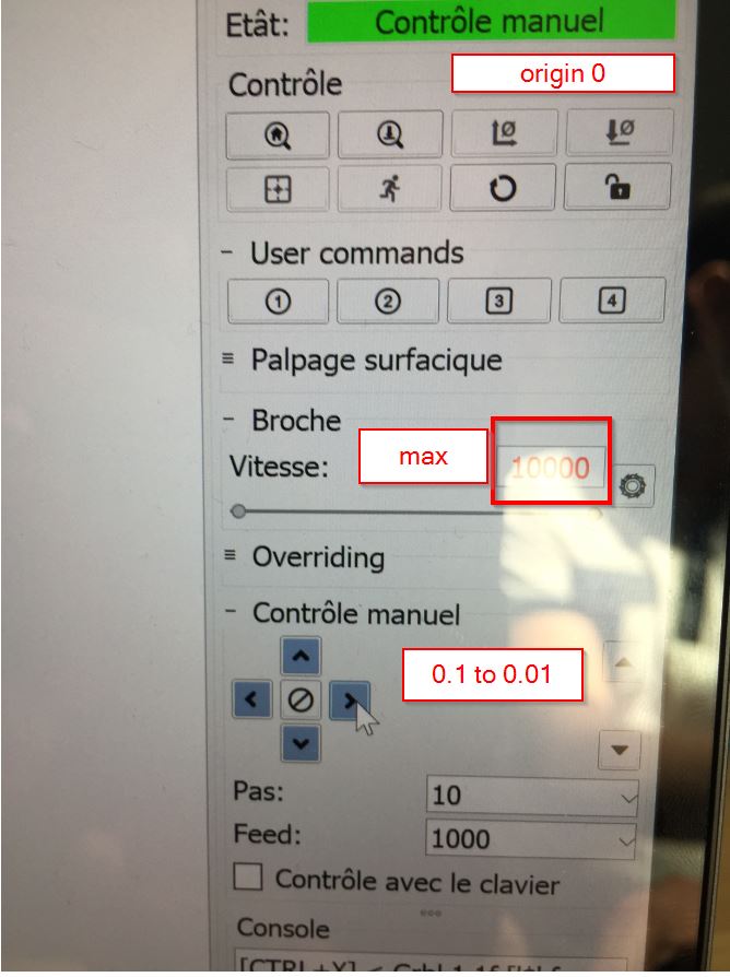
We are going to a corner of the board. Come z gently down. Start from 1mm to 1mm. When you are close, go to 0,1 to 0,1 for touching.
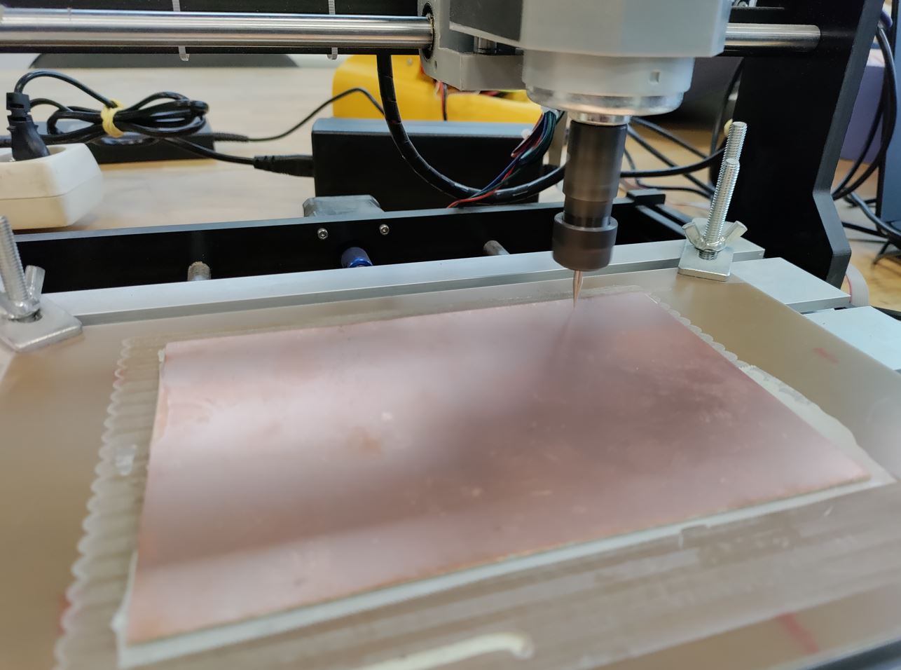
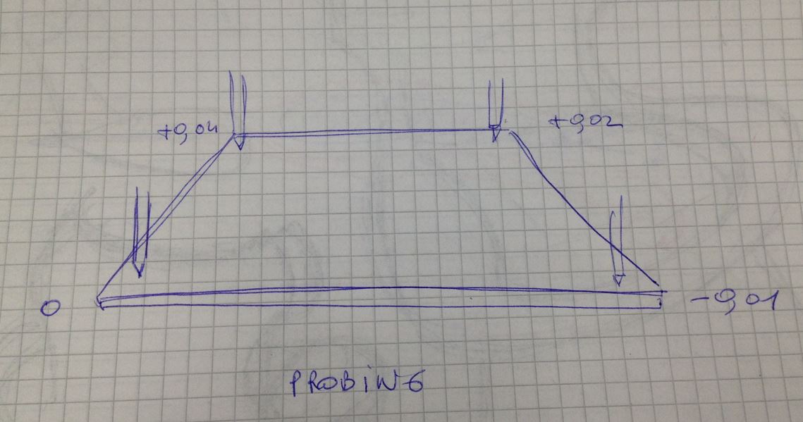
We have 0.05 of difference which is good enough.
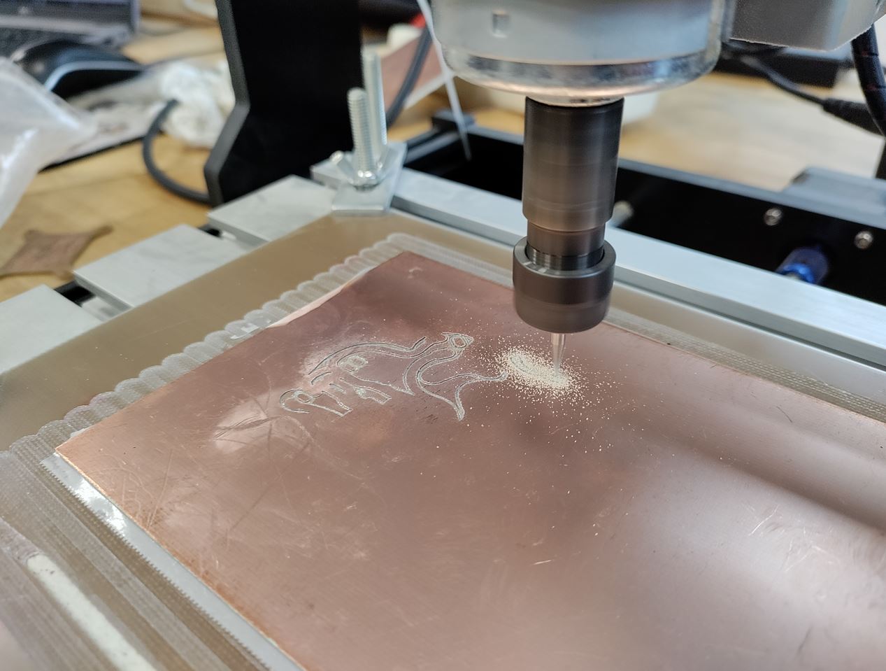
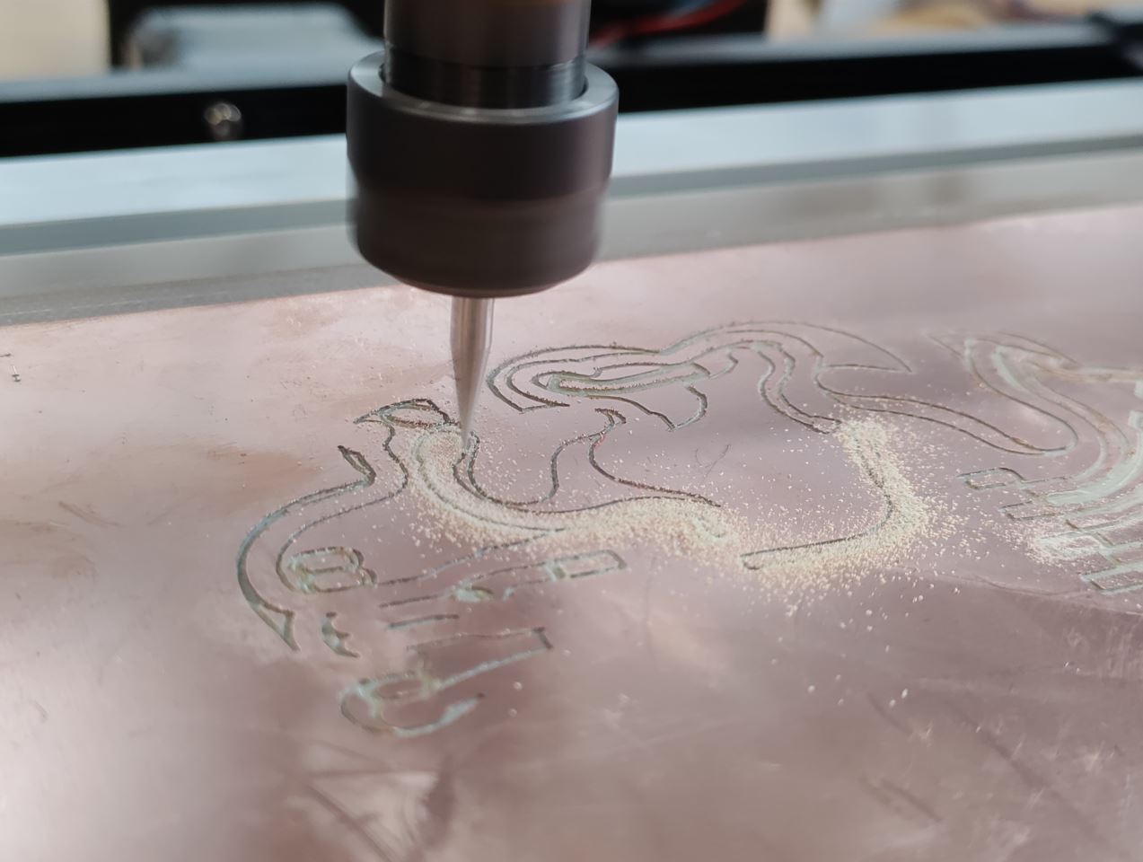
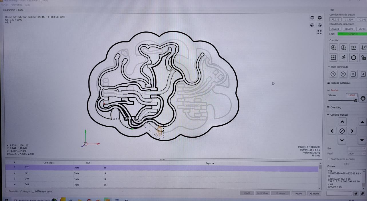
I got my board after 1 hour and 15 minutes. The outlines png has been loaded and ready to process.
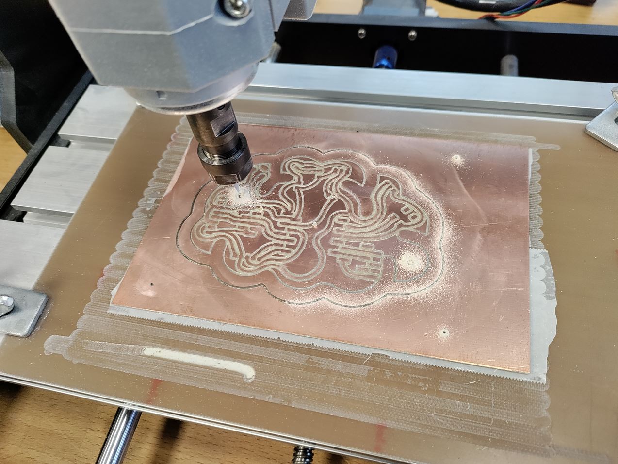
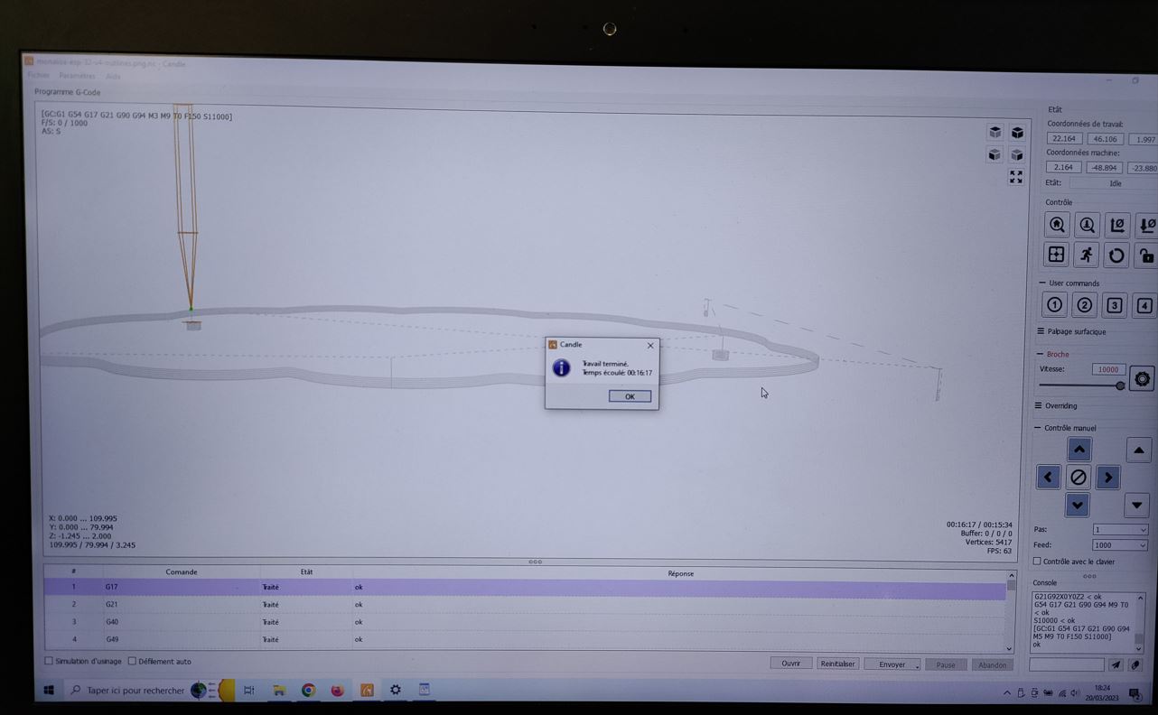
It takes 16 minutes.
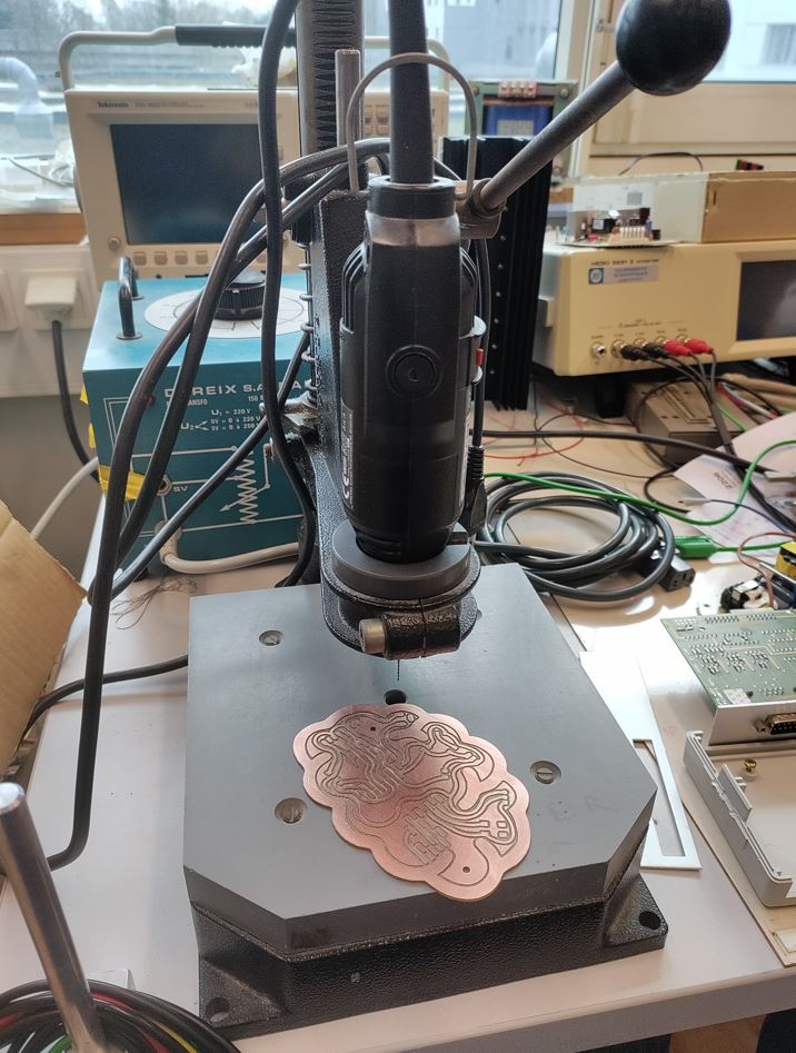
Drilling
I have to make some drills manually, my colleague Sylvain told me that the 3018 does not really like drillings.
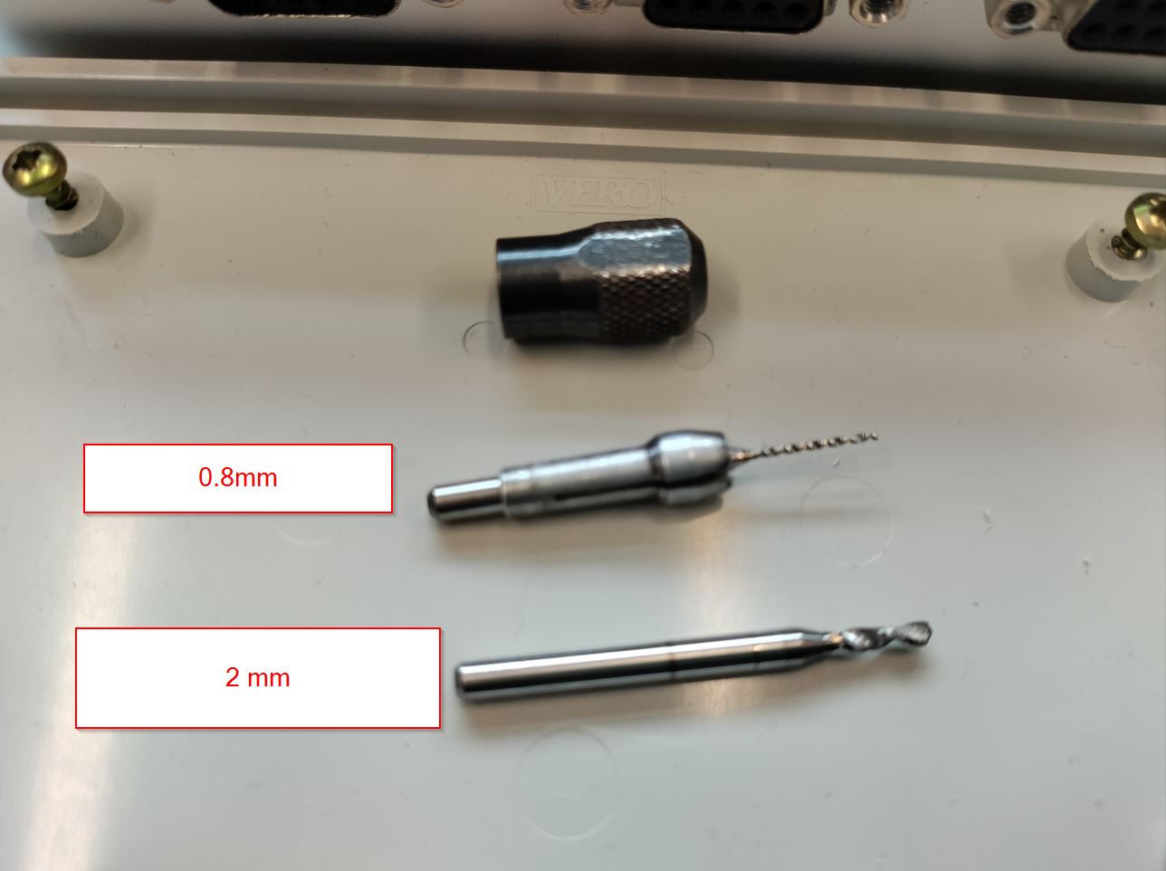
First turn at 0.8mm for the pin header and the DC plug has a 2 mm pass to complete.
.
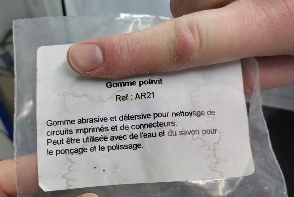
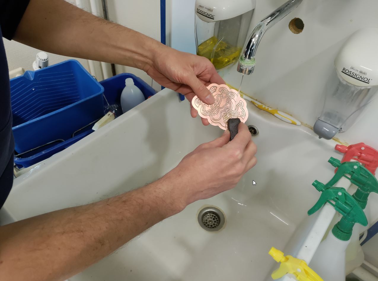
Cleaning board.
You can clean the board by using the sanding stone.
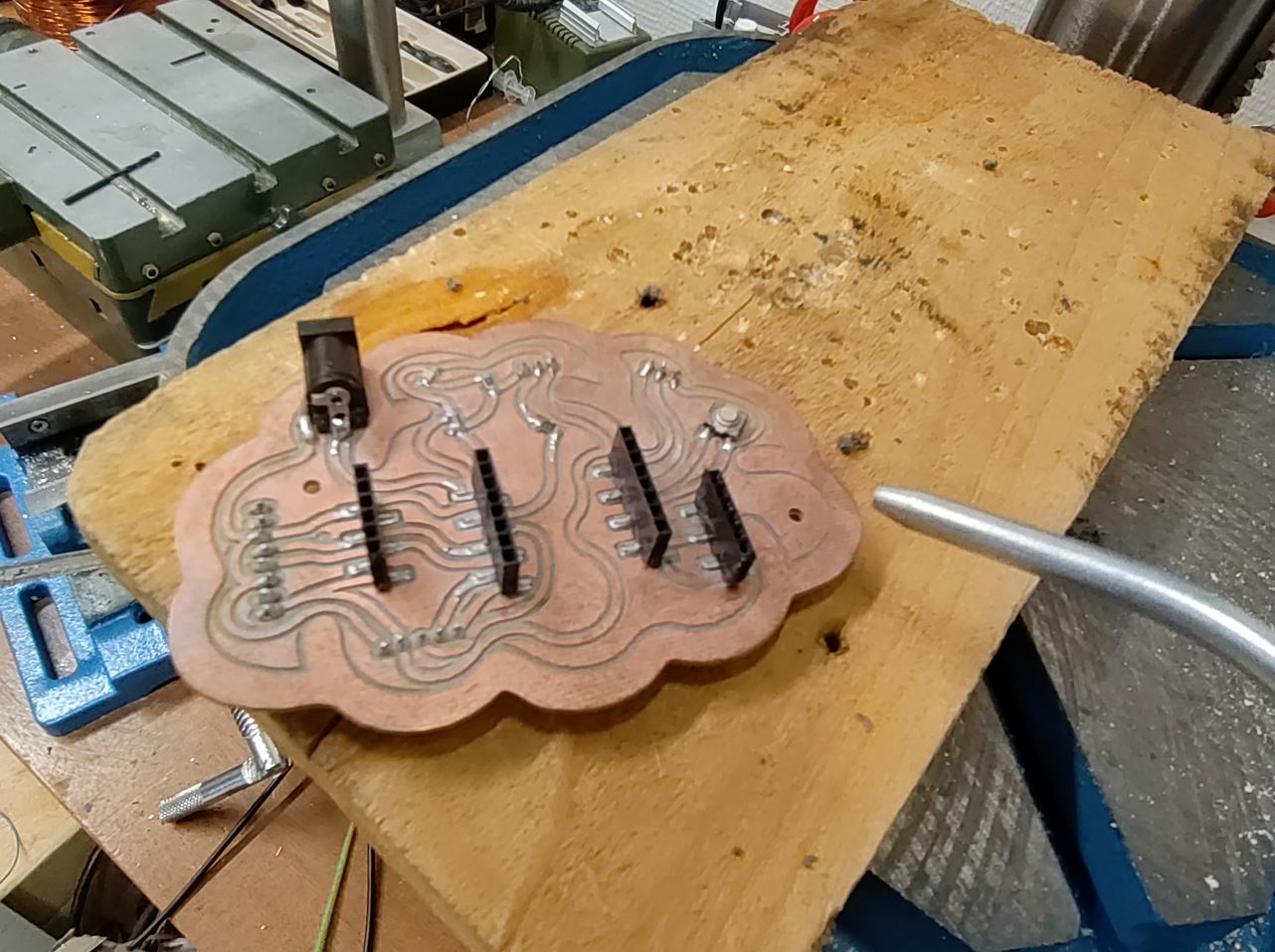
Soldering
foam board
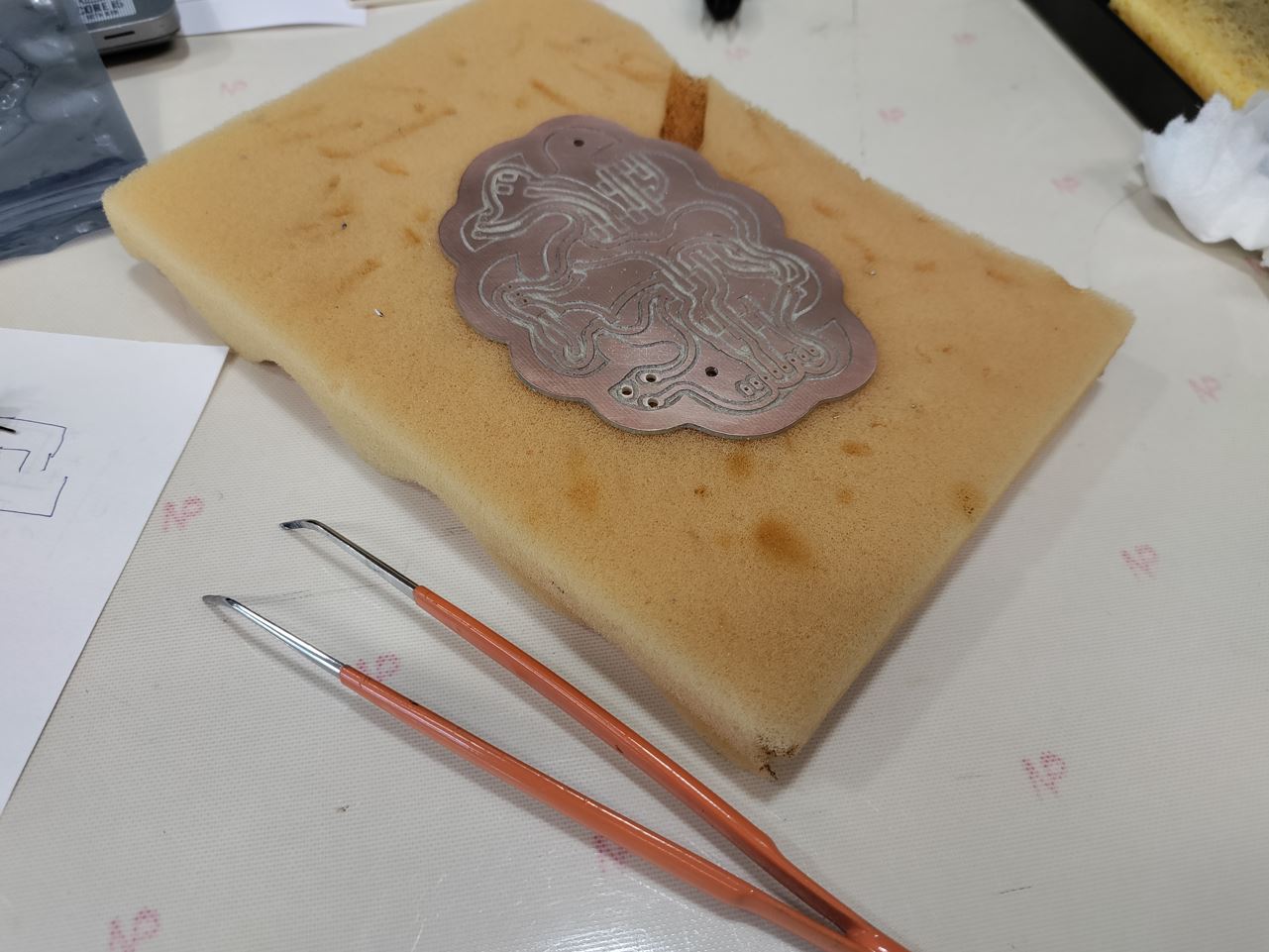 It is very practical to keep your board easy to solder.
Syringue Pasta
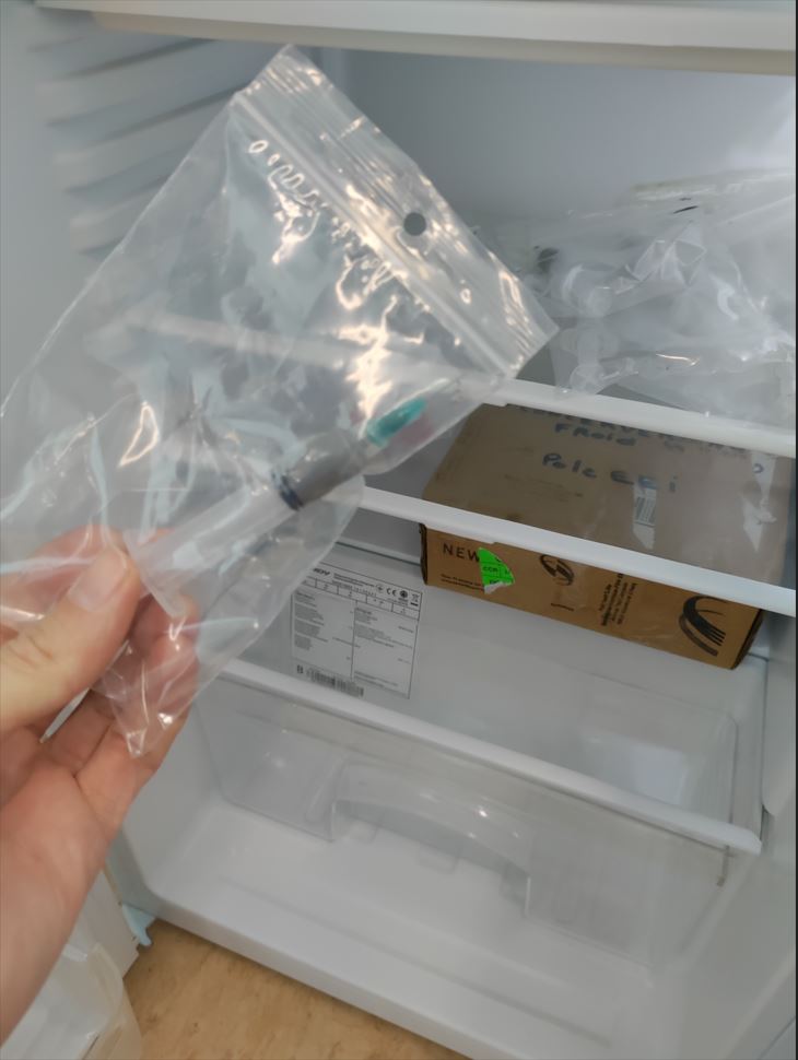 I like to use it, it is very easy. It has to be kept in the fridge.
(40% lead /60% stain)
I like to use it, it is very easy. It has to be kept in the fridge.
(40% lead /60% stain)
Find the polarity on LED
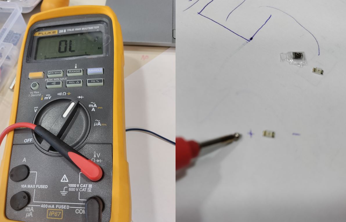
I have set up the multimeter on Diode function and find the polarity on my LED.
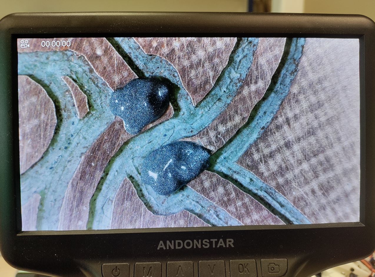
Then, I have placed two drops of pasta for the LED.
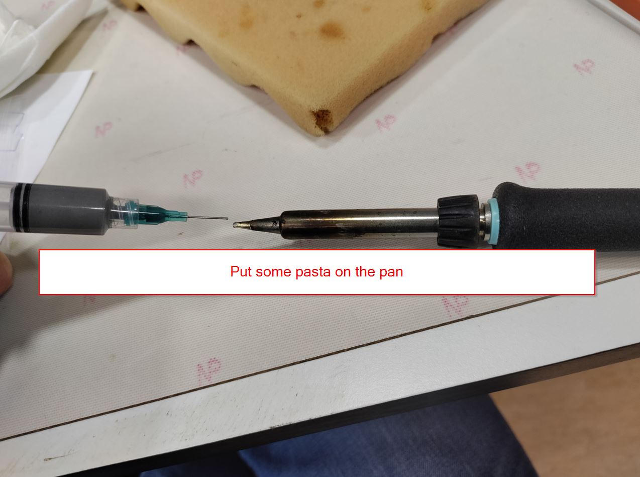
First step when you use the iron, you must clean the pan with the wet sponge. After, you put some pasta again. /// at the end of use, you should do the same process. The stain will protect your device for a long time.
I dropped pasta on the place of the LED.
And I soldered my first component.
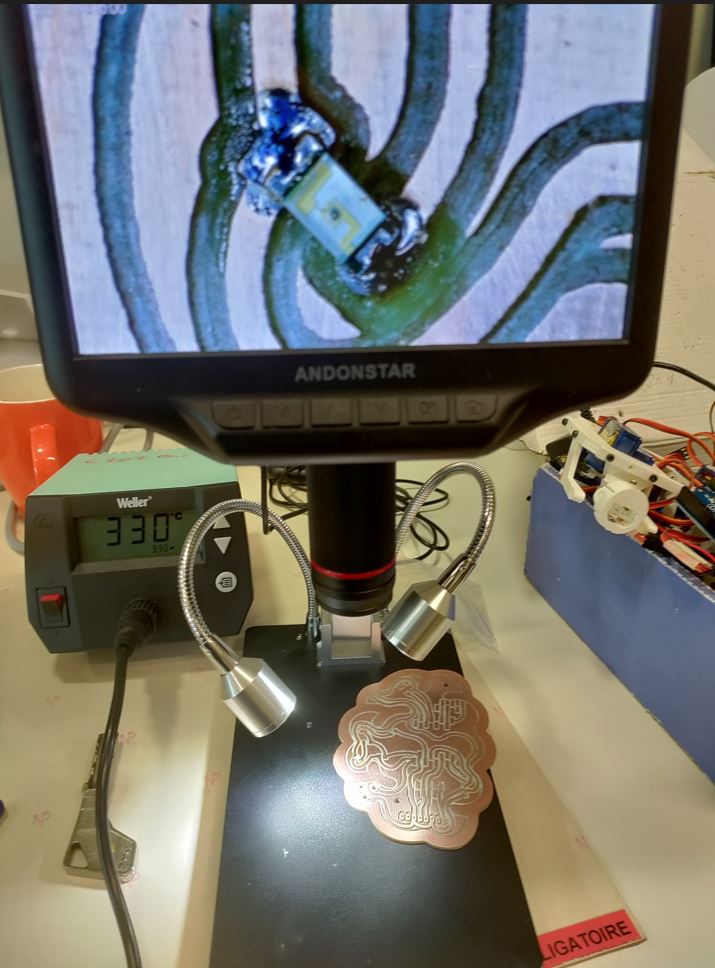
Then the 1microFarad was added to my board…
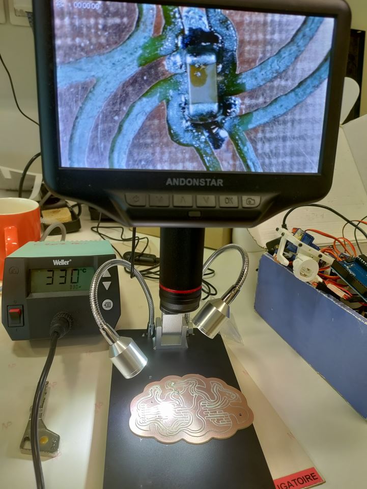
I saw on my board that some copper has to been removed. I gently used my cutter.
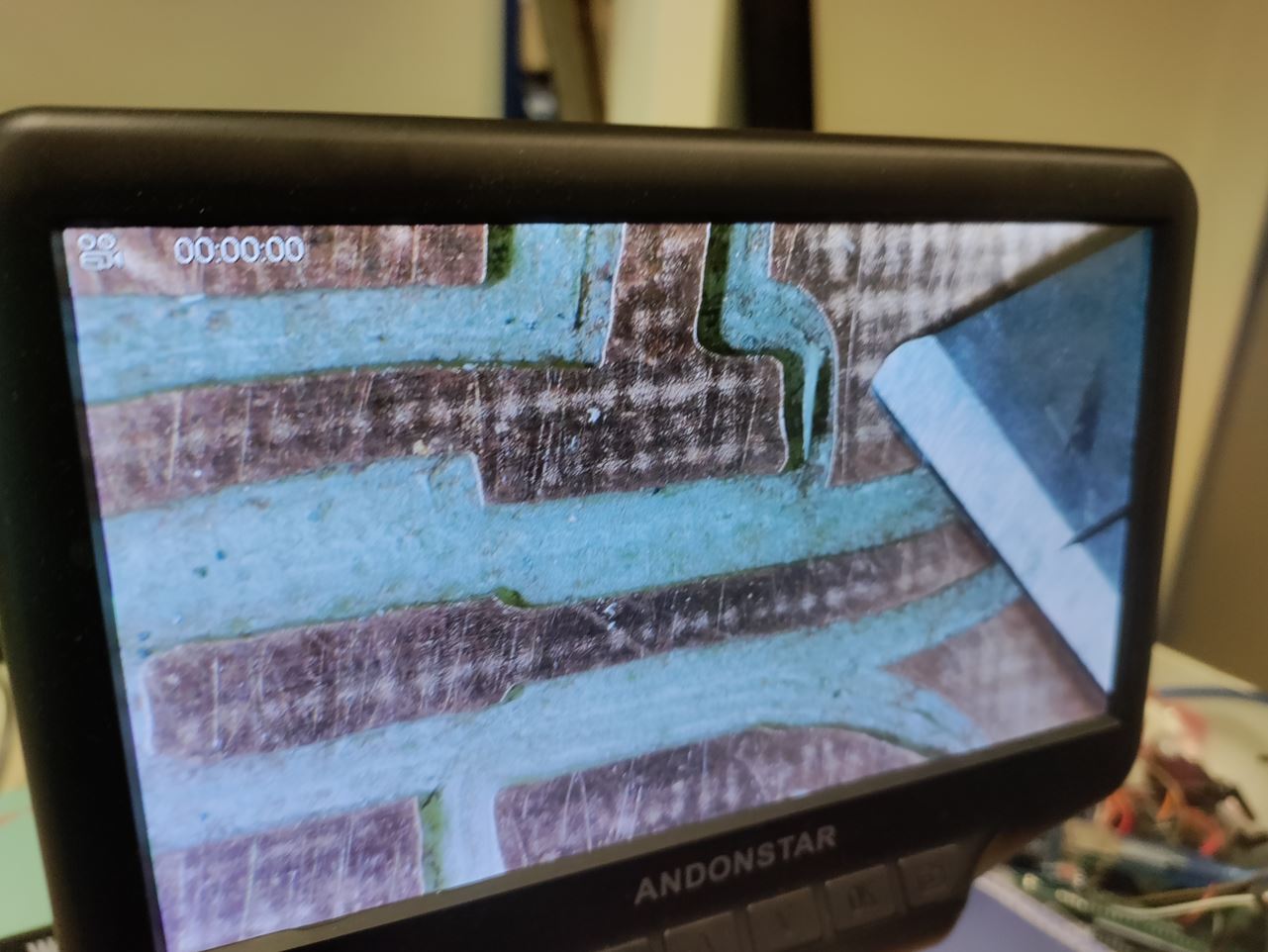
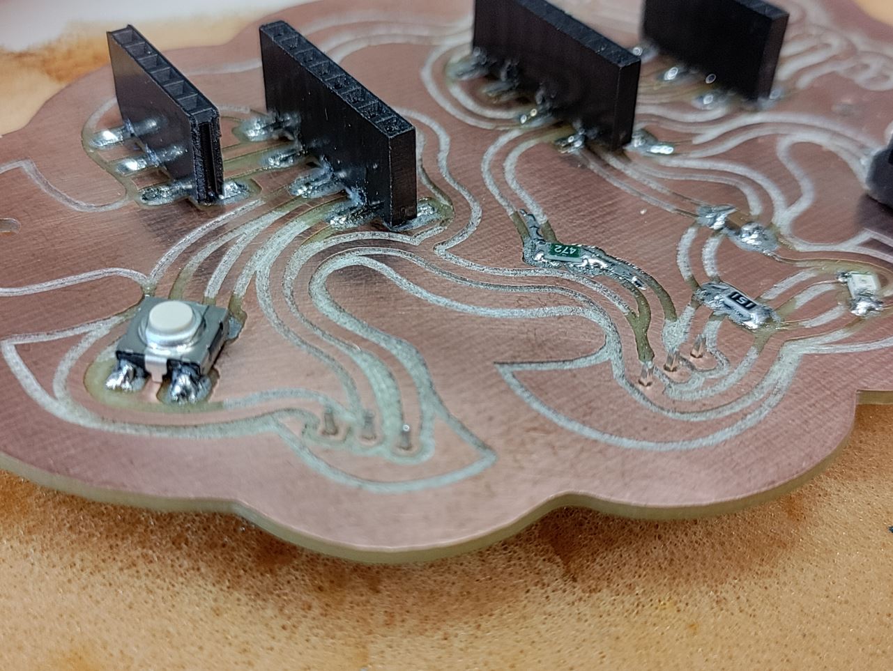
Next, I decided to solder the Switch button.
The switch is fixed to my board.
Sylvain gave me some advices to adjust the esp pinners.
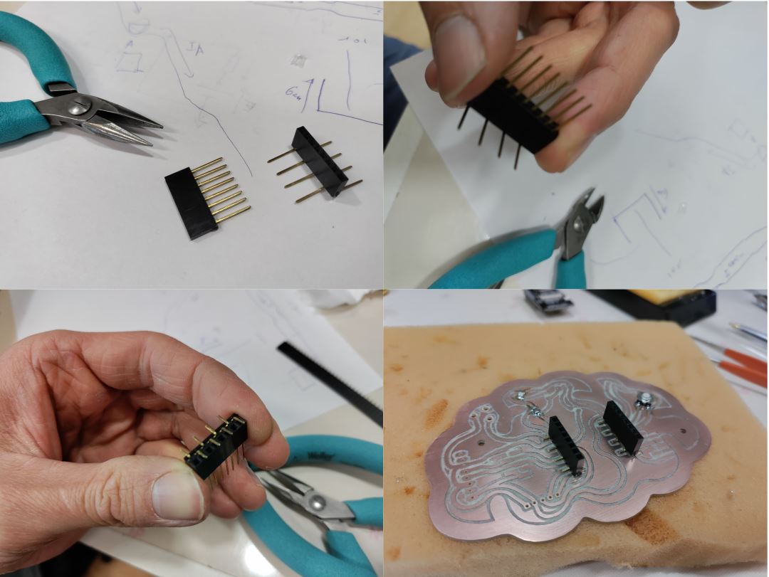
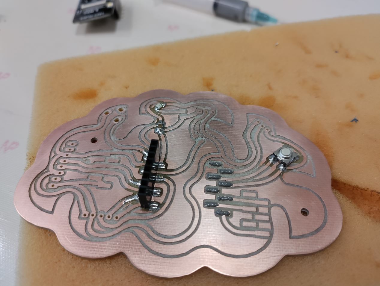
I have plugged the esp-32-cam to help me to have a parallel solering process.
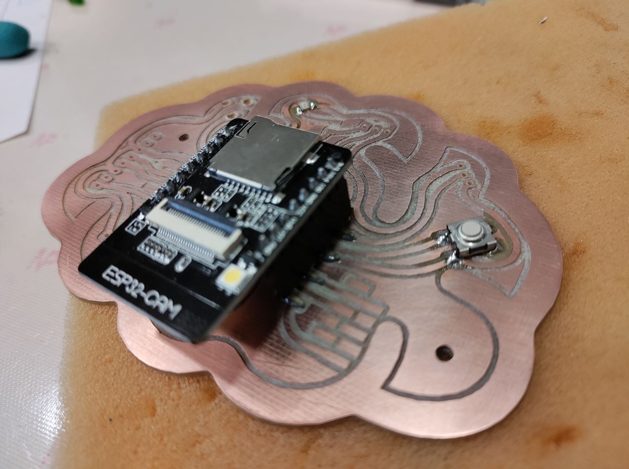
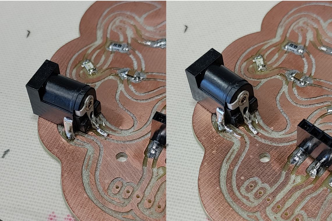
I put more stain at the top of the pins in order to get something strong.
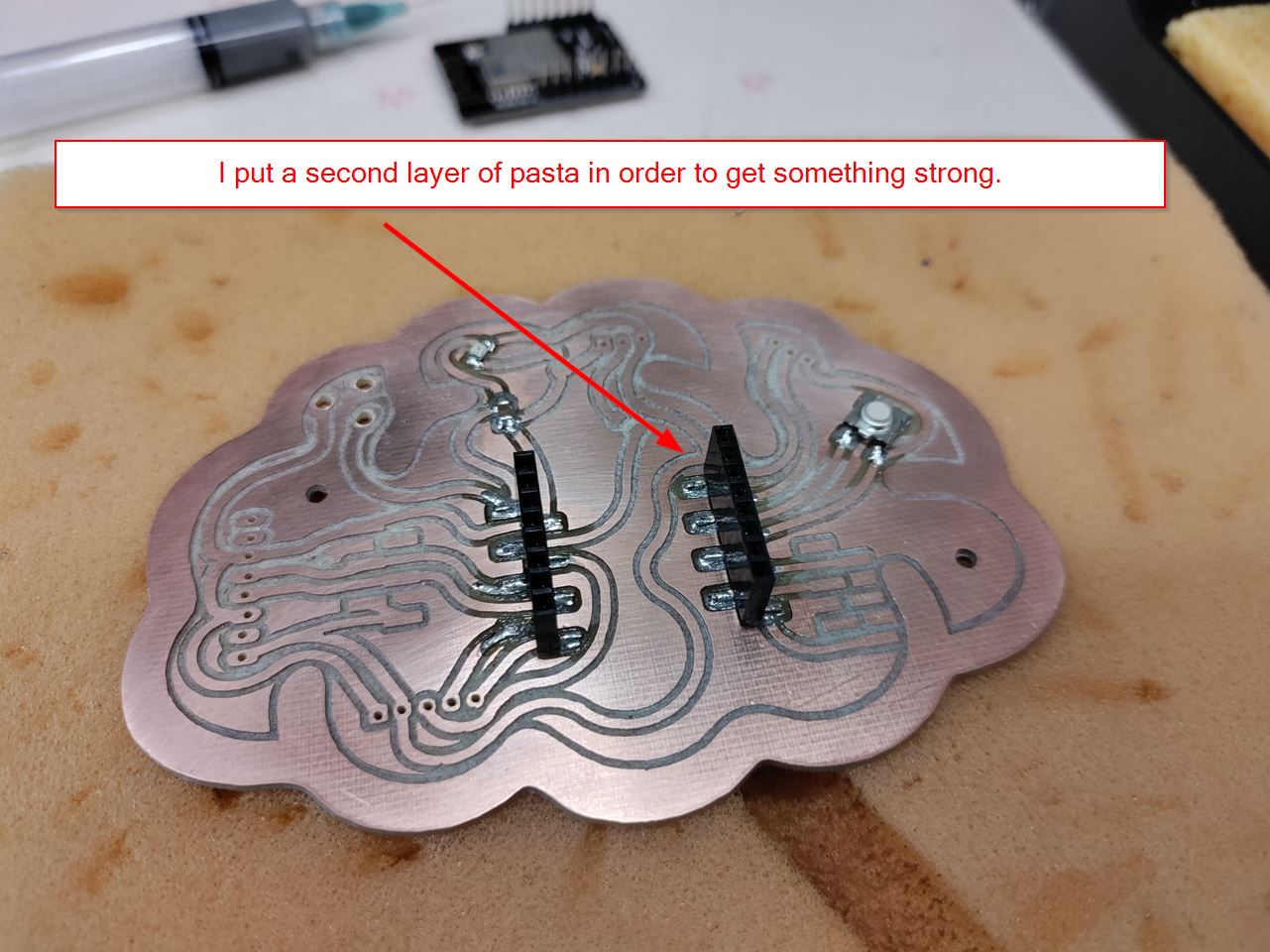
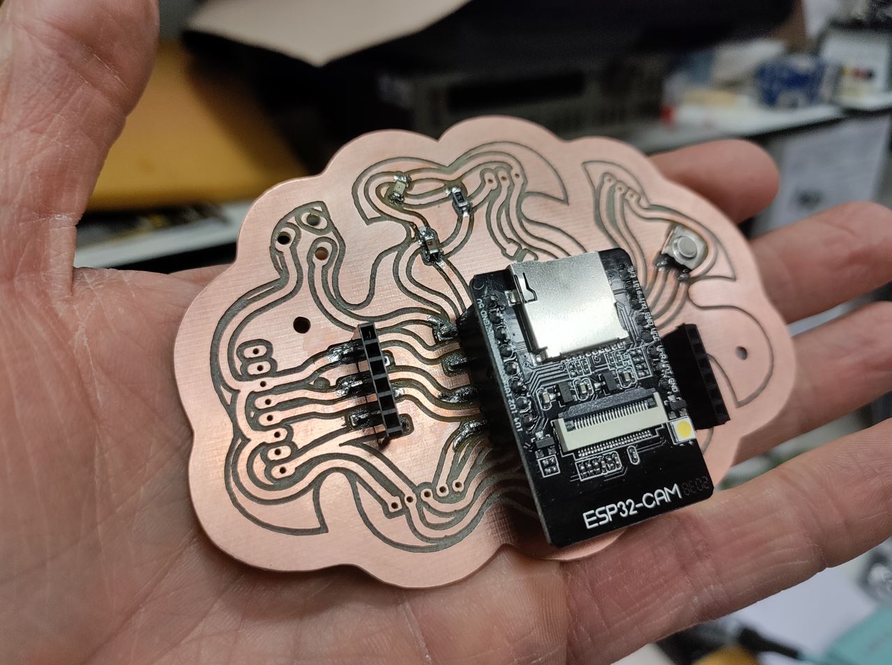
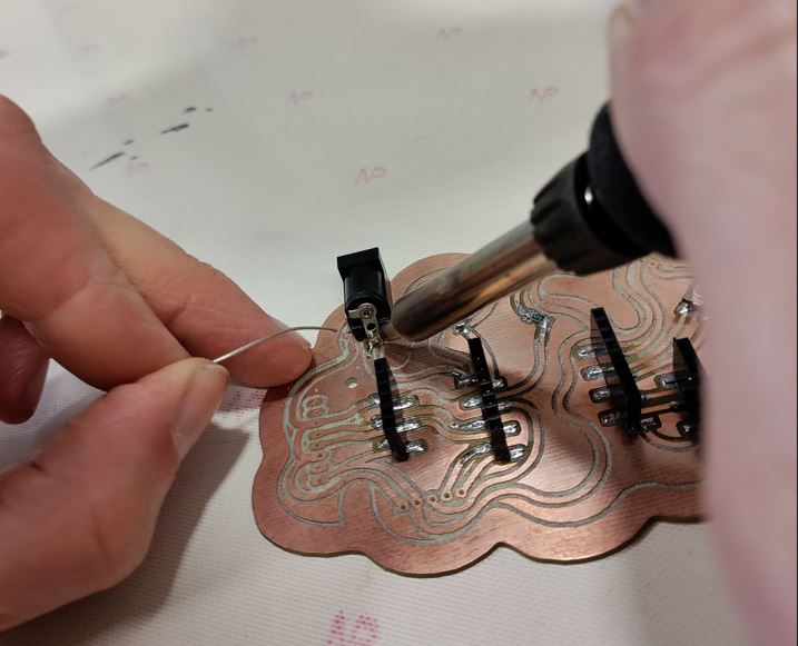
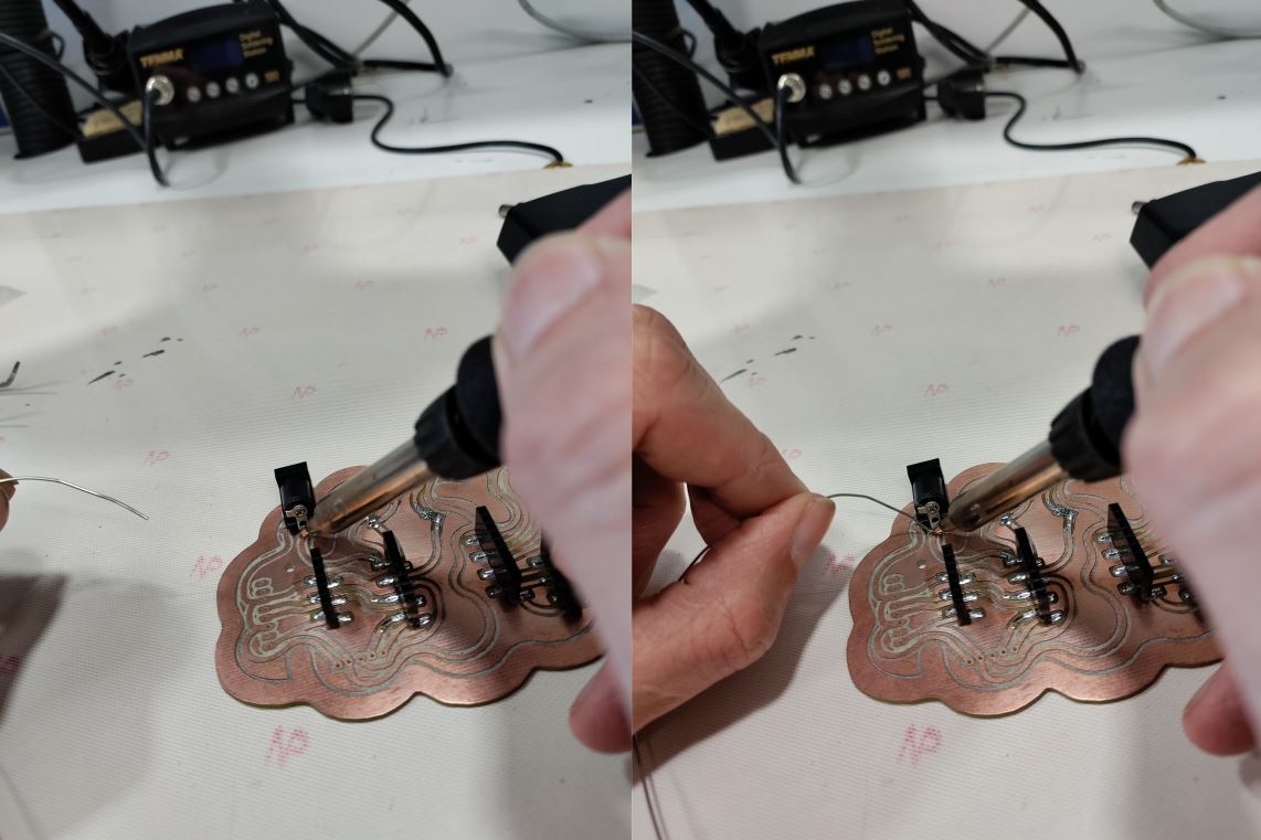
So here comes my board part 1 : pasta syringue. Now we will continue to part 2 : wire soldering.

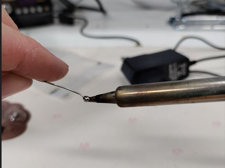
wire soldering
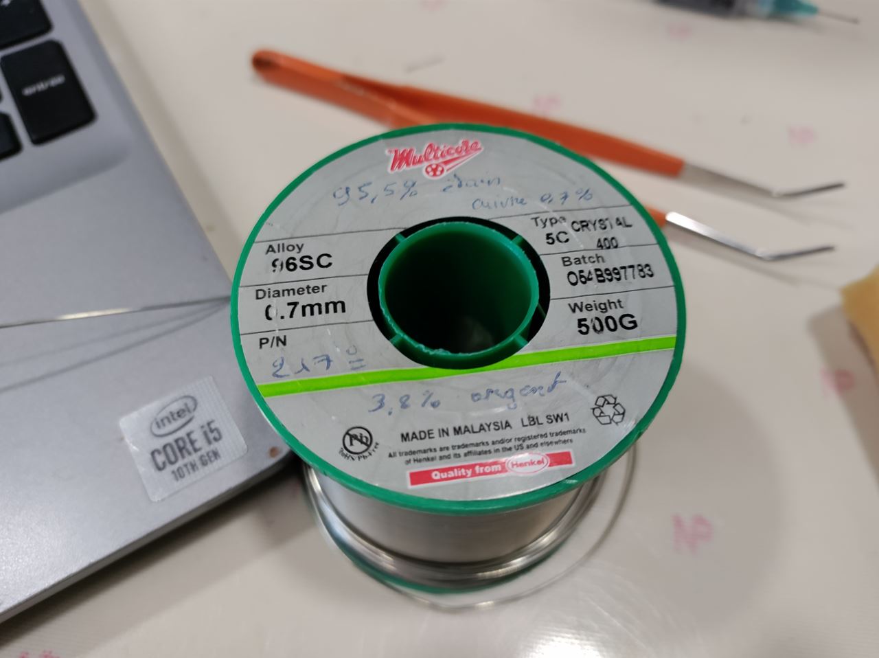
| Brand | Multicore - Type 5C - Chrystal 400 |
|---|---|
| Alloy | 96SC |
| Diameter | 0.7mm |
| stain | 95.5 |
| copper | 0.7% |
| silver | 3.8% |
Again, I have cleaned my iron with the wet sponge. And I put some stain on my pan.
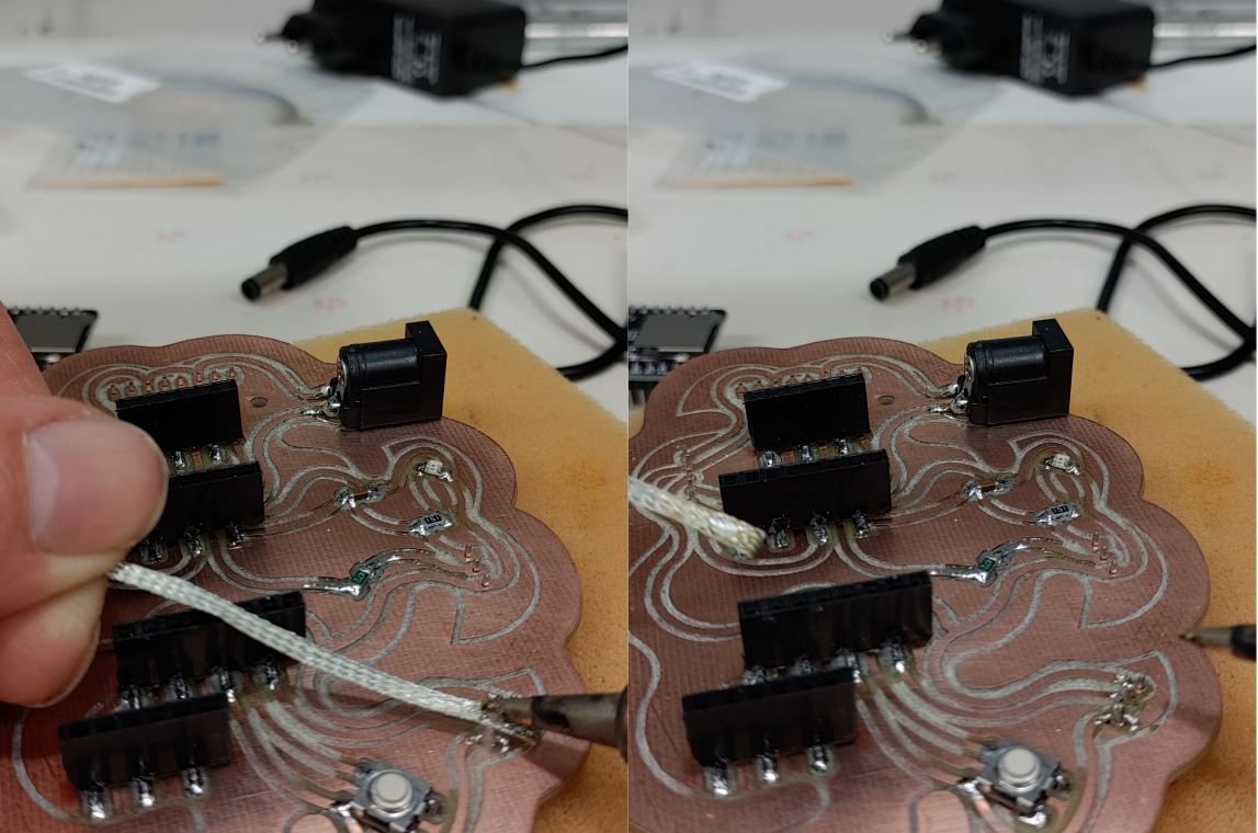
Bad soldering, using “tresse”
I put some stain on the pan and I put the “tresse” to the fat pin.
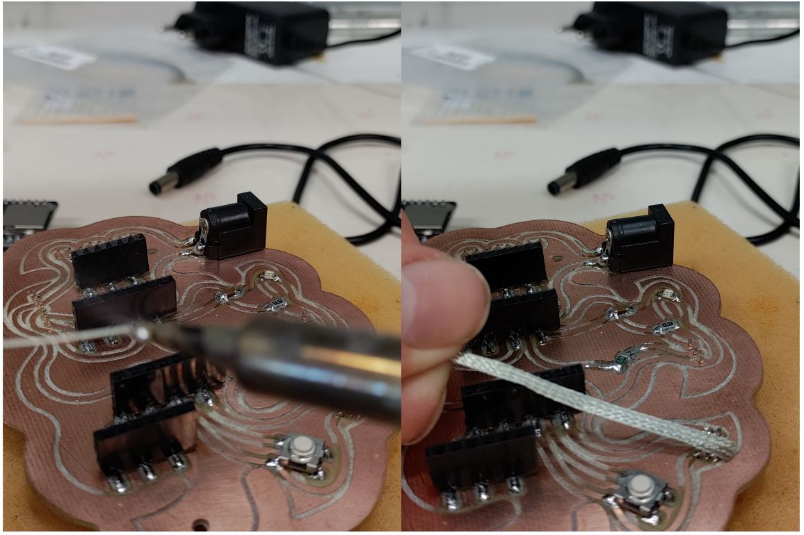
The hot pan is down to the top of the tresse. And the undesired stain is going up to the “tresse”. You remove the iron and then the tresse. The soldered pin is now thiner than it was.
All sticky spaces due to the double sided tape have been removed by the acetone.
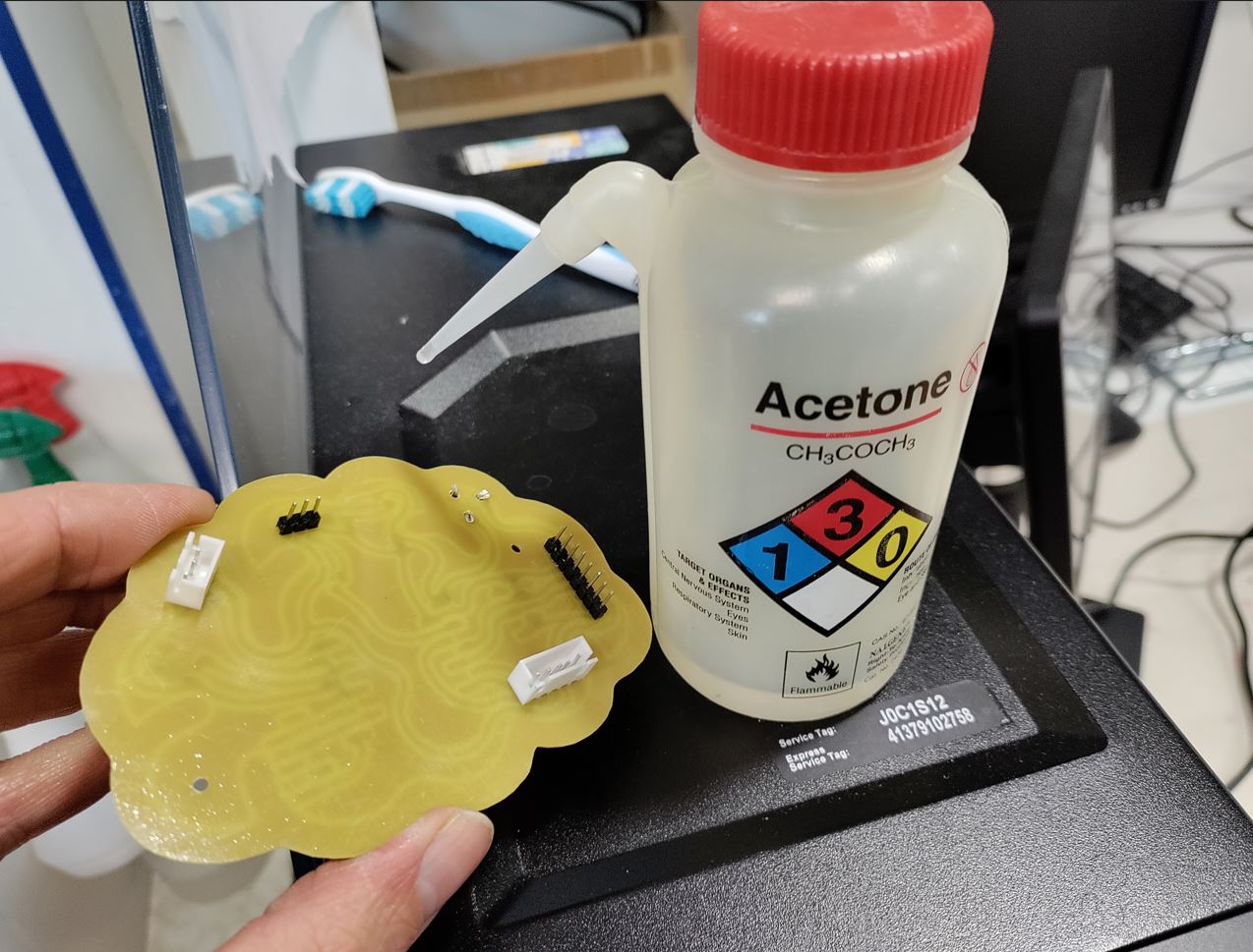
You clean directly the board by using isopropanol again. Otherwise acetone will destroy your connections.
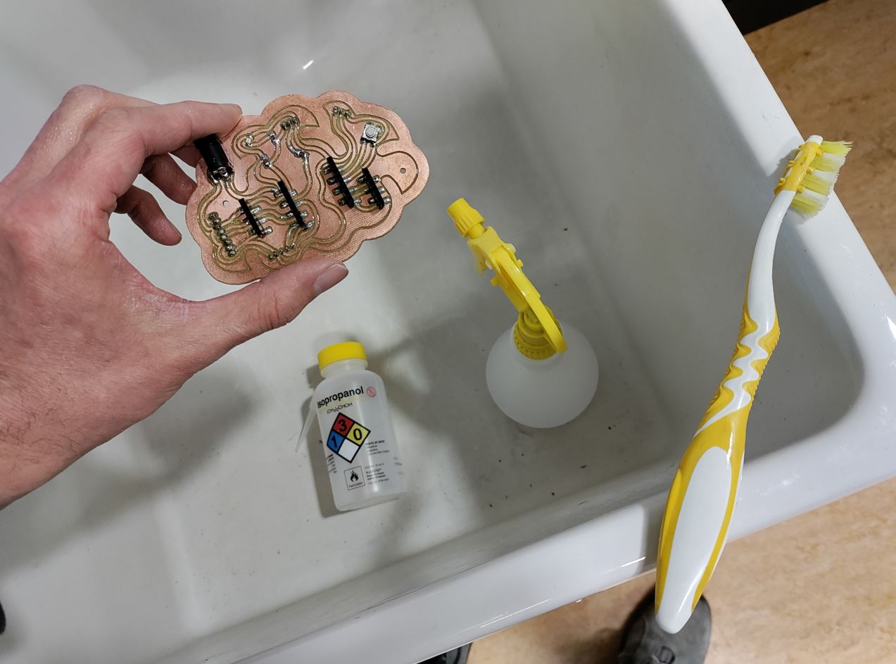
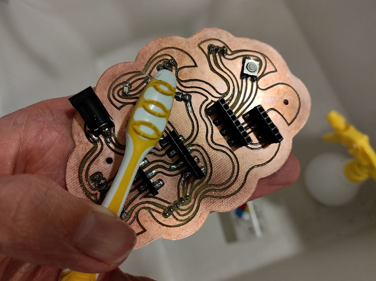
I gently use air jet to dry the board.
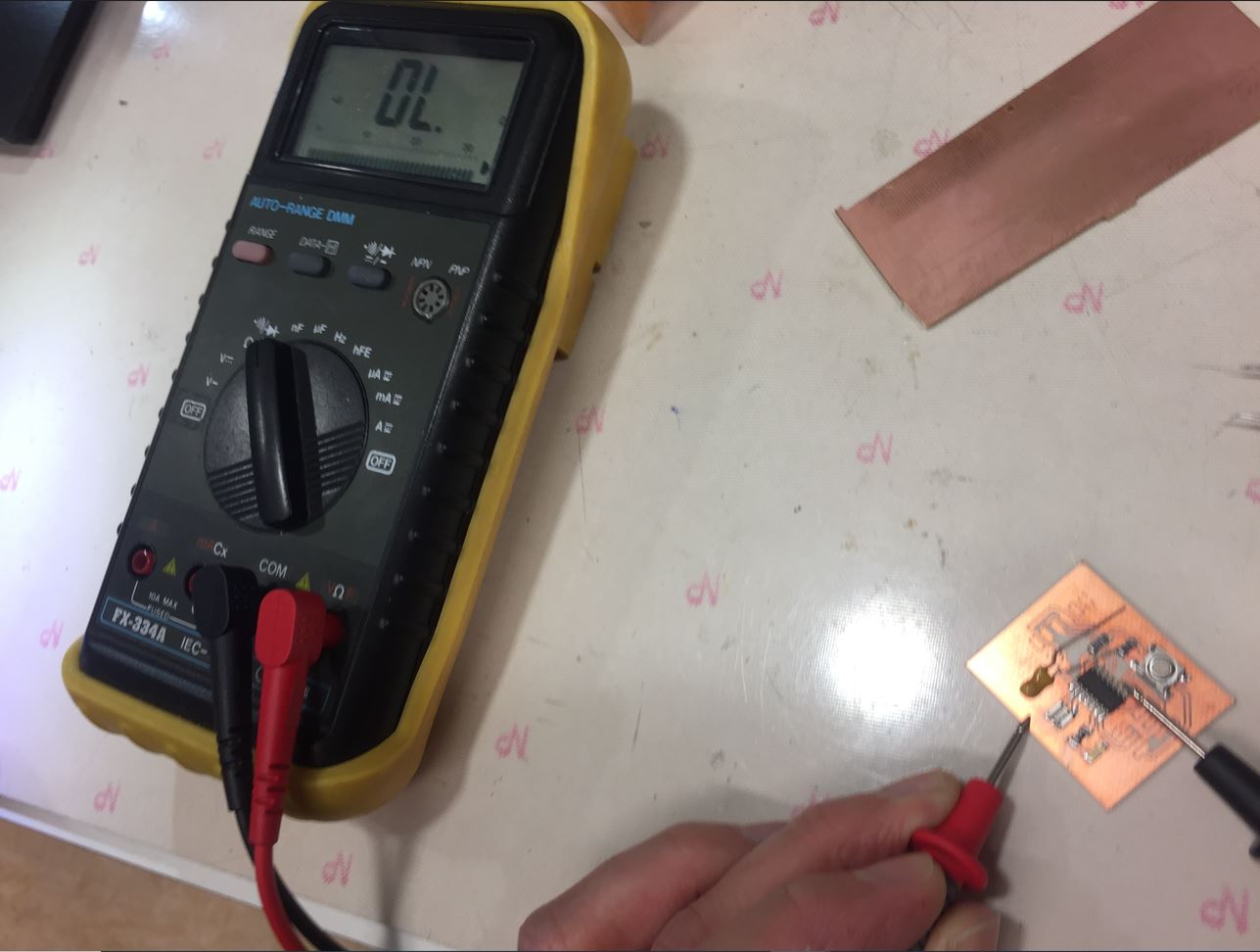
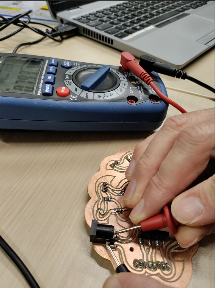
Checking non continuity.
The goal is to know if there is any shortcut. I set up the multimeter on ohmmetre and see if there is a bip, or the 0 ohms sign. The average 0.793 MΩ.
C:\github\2023\fabien-jonckheere\docs\images\week07\checking-continuity.jpg
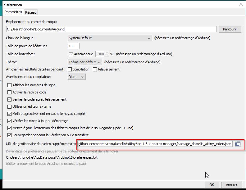
ARDUINO
Arthur, another fabmanager of my school helped me to find the link to get the property of the ATtiny boards useful link
Next, we moved to ARDUINO to set up the Attiny board mamanger. Arduino>files/preferences
ELECTRONICS EXTRAS
“Lorem ipsum dolor sit amet, consectetur adipiscing elit, sed do eiusmod tempor incididunt ut labore et dolore magna aliqua. Ut enim ad minim veniam, quis nostrud exercitation ullamco laboris nisi ut aliquip ex ea commodo consequat. Duis aute irure dolor in reprehenderit in voluptate velit esse cillum dolore eu fugiat nulla pariatur. Excepteur sint occaecat cupidatat non proident, sunt in culpa qui officia deserunt mollit anim id est laborum.”
Useful links
Code Example
Use the three backticks to separate code.
// the setup function runs once when you press reset or power the board
void setup() {
  // initialize digital pin LED_BUILTIN as an output.
  pinMode(LED_BUILTIN, OUTPUT);
}

// the loop function runs over and over again forever
void loop() {
  digitalWrite(LED_BUILTIN, HIGH);   // turn the LED on (HIGH is the voltage level)
  delay(1000);                       // wait for a second
  digitalWrite(LED_BUILTIN, LOW);    // turn the LED off by making the voltage LOW
  delay(1000);                       // wait for a second
}
Gallery

Video
From Vimeo
Sound Waves from George Gally (Radarboy) on Vimeo.