10. Machine Design
As a lab team, we are going to build a machine during two weeks. THere is no class and recitation. It is also a time for missing documentation from early weeks.
research and recitations
http://machines.fabcloud.io/
machining recitations: jens dyvik Nadiah Peek Lnmachines. Marcello Tania. Jake Read. clank: fabricatale, modular CNC
Modular things. by Leomcelroy.github.com/modular-things/modular-things/blob/main/readme.md http://osap.tools/ (!) https://github.com/modular-things/modular-things-circuits
Quentin Bolsee gitlab.cba.mit.edu/quentin urumbu.
Tiny machines for big ideas picomachines.com (Rahul rajan htmstm(1)A)
pico v2
2022 buthan video machinning
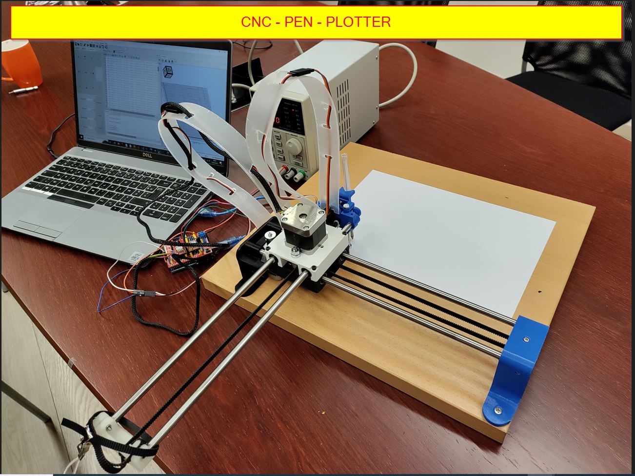
CNC pen Plotter Machine.
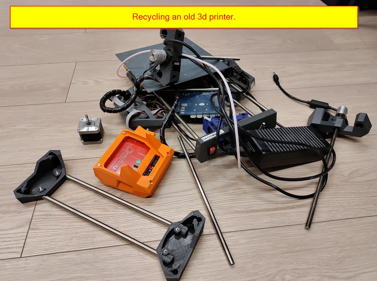
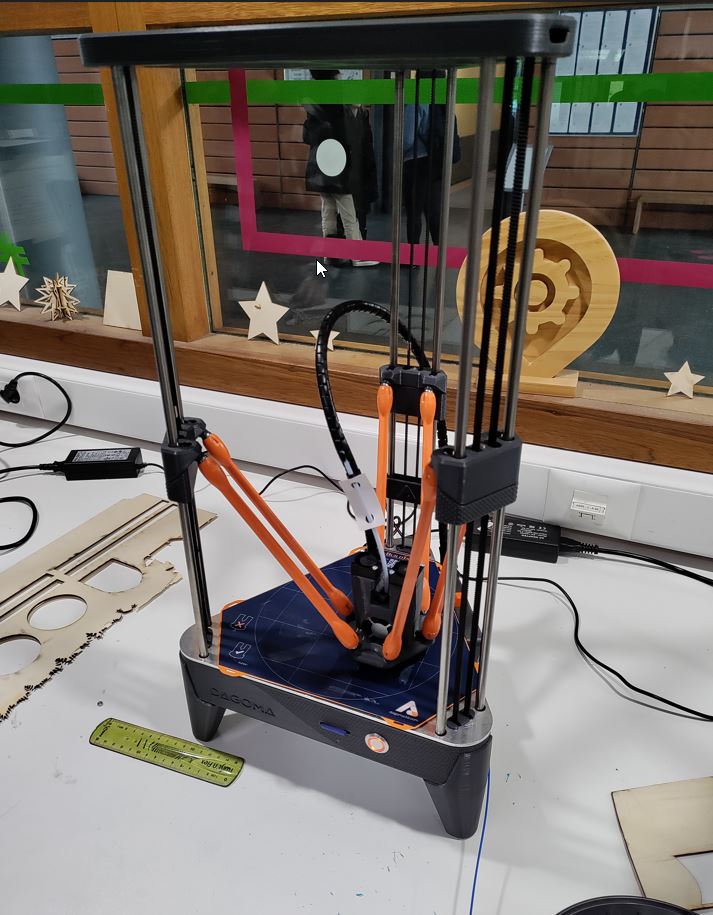
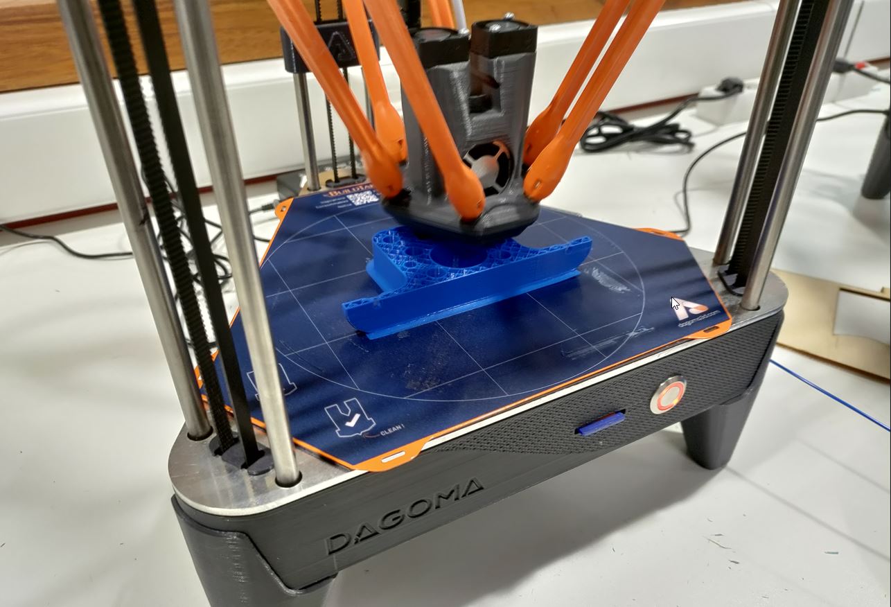
For 2023, I have decided to make my own CNC machine.
https://fabacademy.org/2023/labs/agrilab/files/fabien_2023_machine_week_nosound.mp4
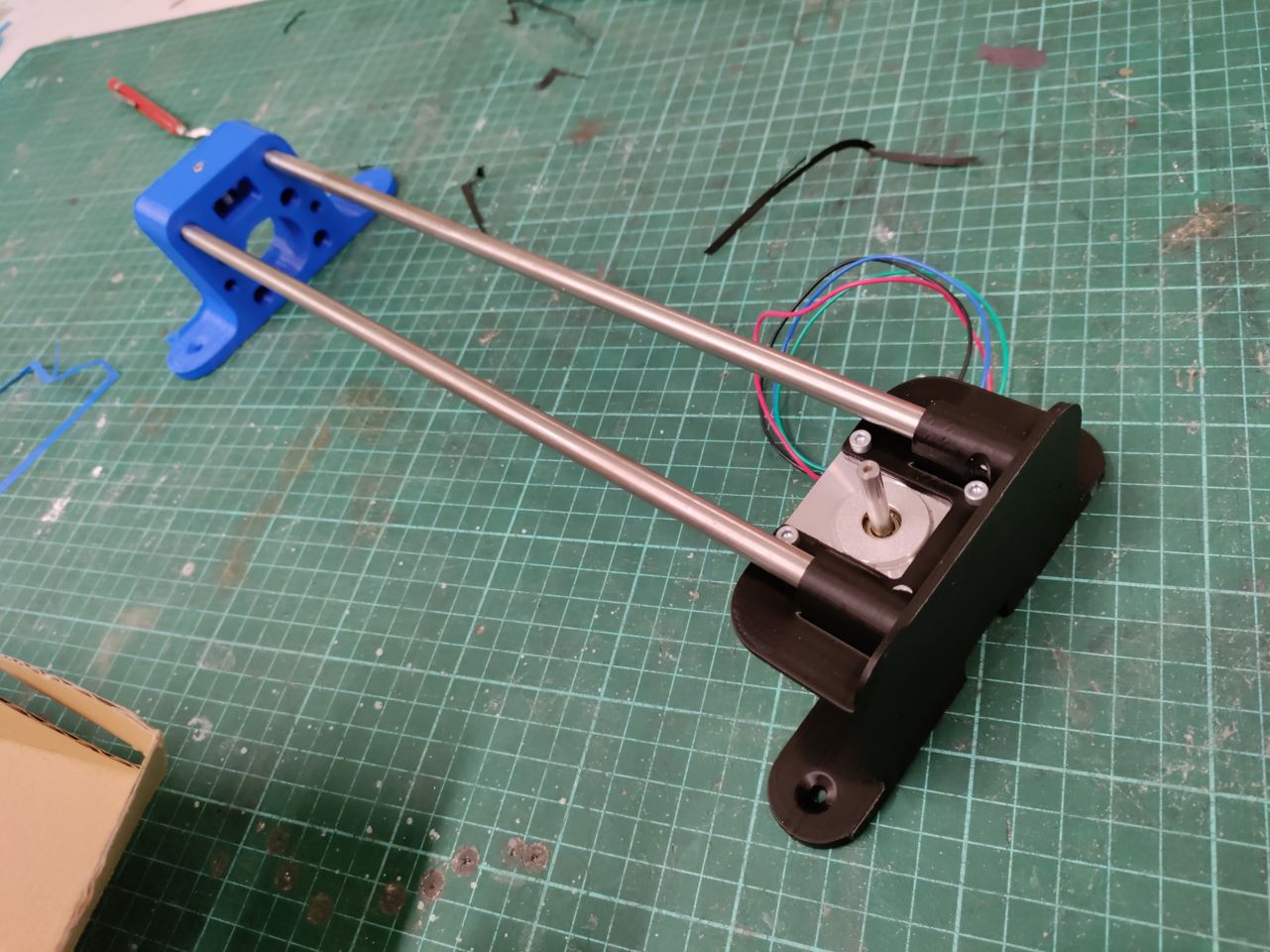
from an old 3d printer
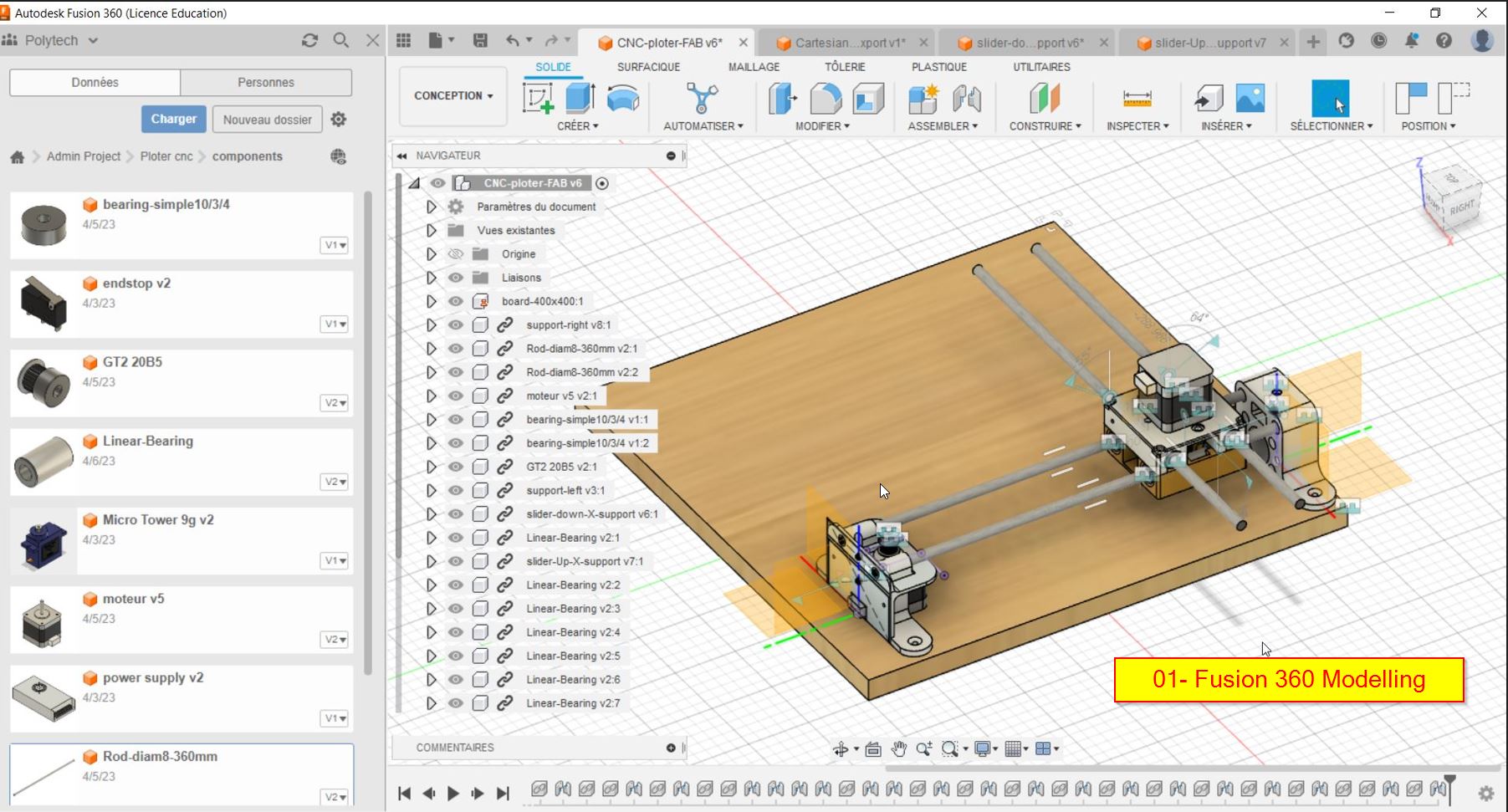
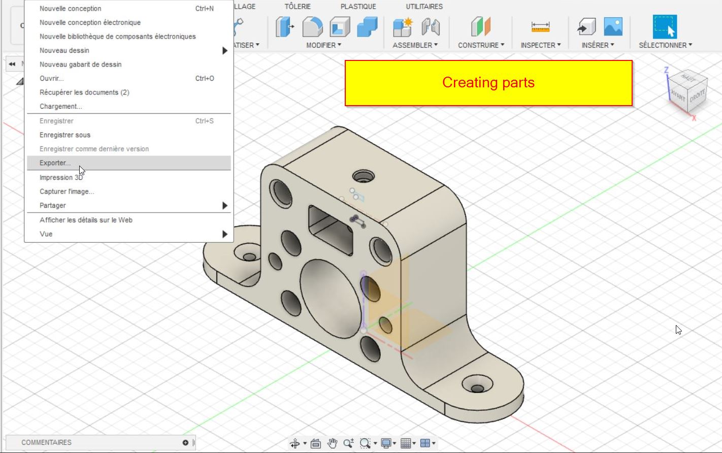
FUSION 360°
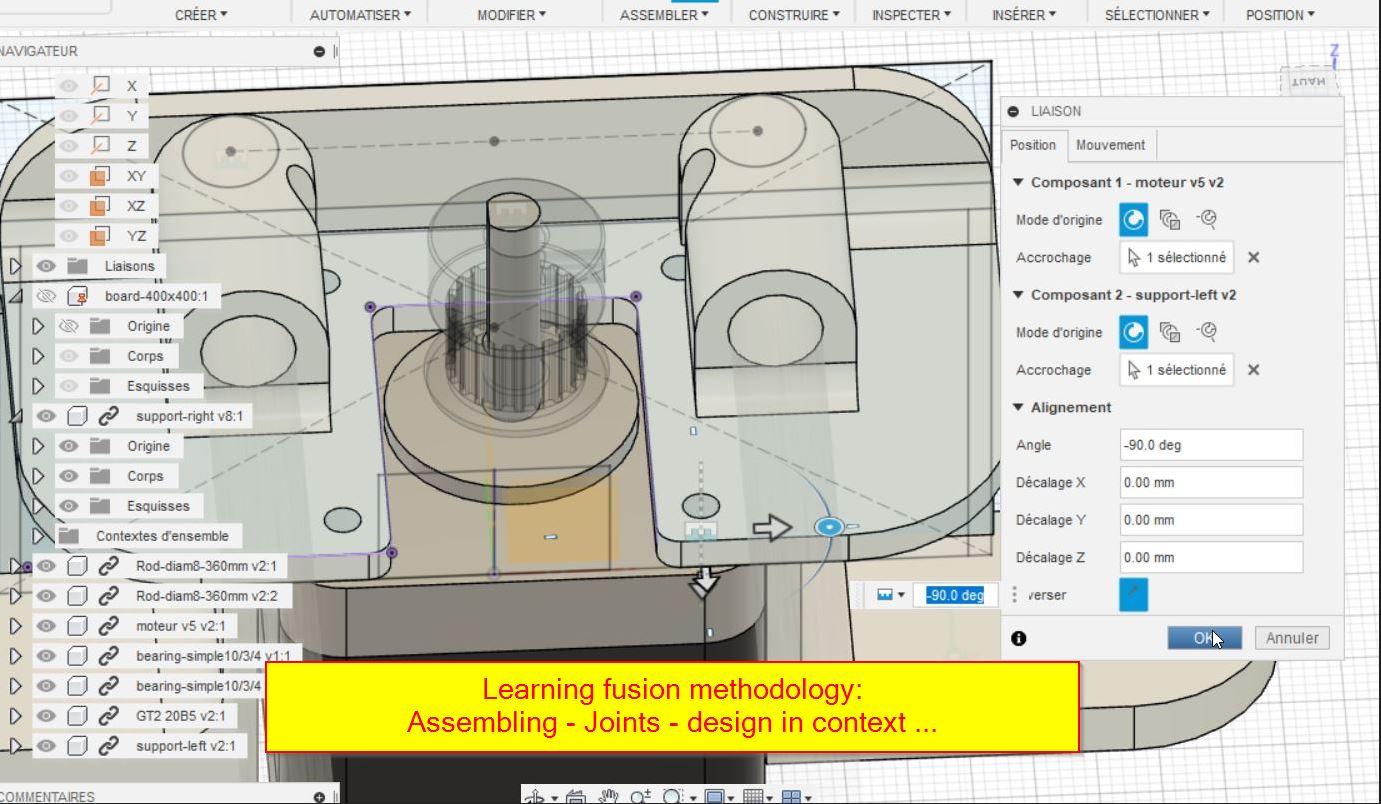
In the past, I have modelled a lot of parts, but I was not involved in a design team. Last semester, I have discovered Dassault Systems Catia 3D experience in my school. The strict method to model is quite efficient. But 3DX is not very practical in a fablab. I decided to get back on Fusion 360. My colleague Mathieu explained me a bit about the assembly and the constraints.
SO I will take my design machine week to explain the modelling process. Please go the the assignment 3 : CAD for details.
First way to model: You start a new document and create a part. You build each part separately and add everything in a new file. It will be the assembly file.
Second way: You design in contest. It means, you build all your parts in a file. There is a hierarchy to follow.
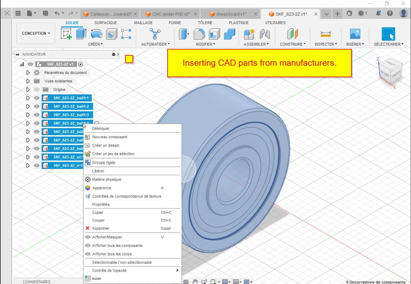
I will start with a assembly file and make the wooden board. Then the other parts will be made separetely and inserted in the assembly.
You can find already made parts on website such as grabcad or traceparts. For the bearings, the SKF brand provides their own 3d Parts. Neitherless, I had some difficulties to make joints, there were missing parts to the joint.
3D printing
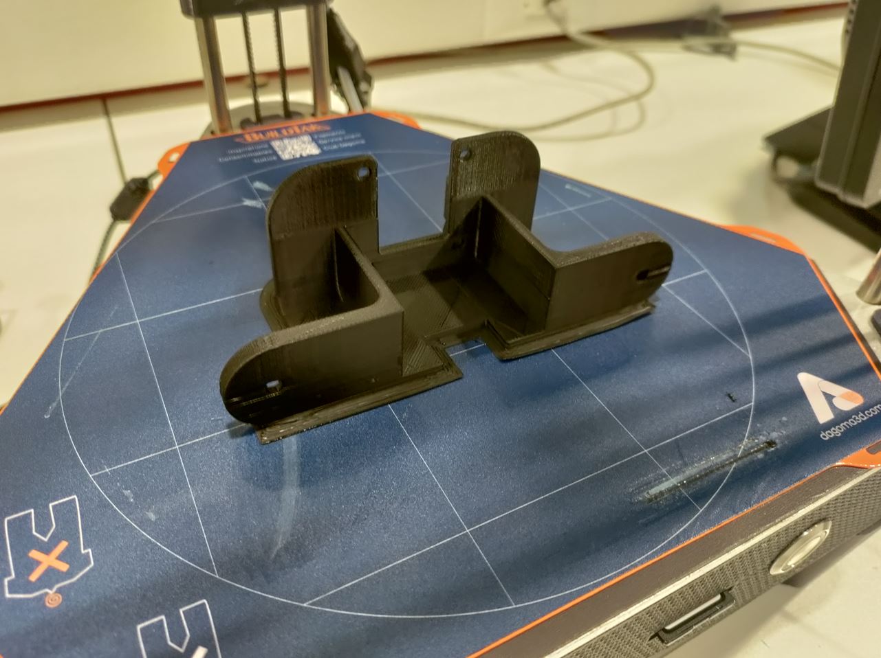
cnc controller
Alimentation
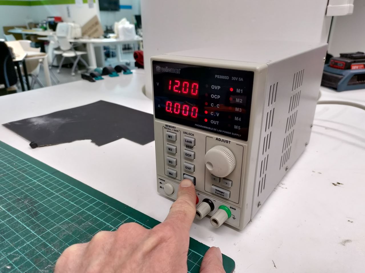
12V-2A
Grbl

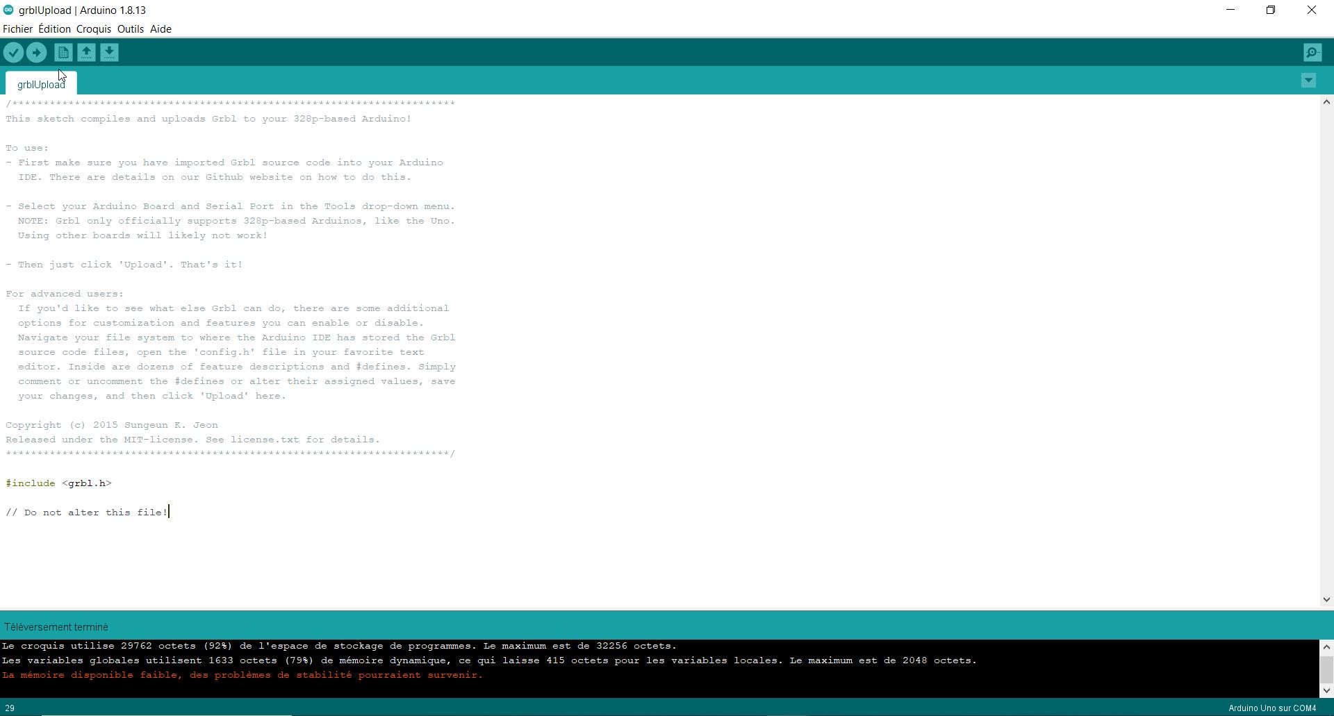
Later, I switched to MI-GRBL. It is already programmed to have the z axis.
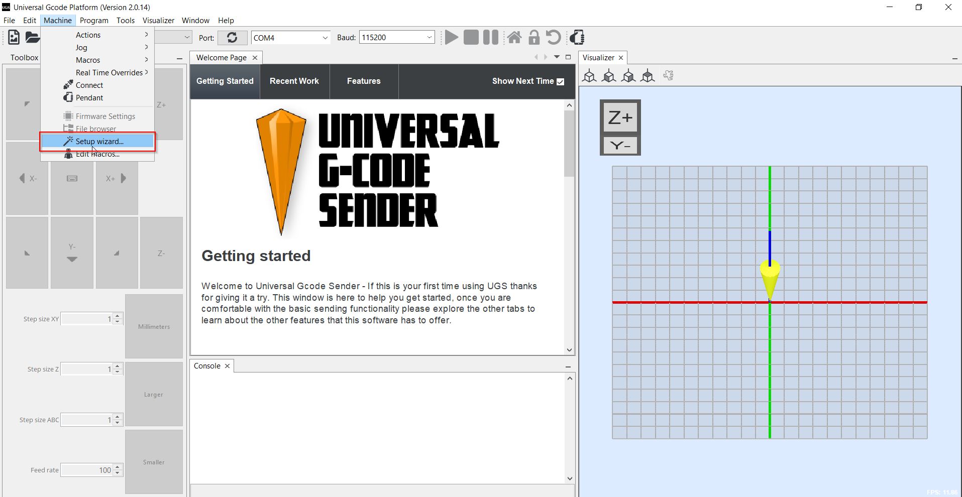
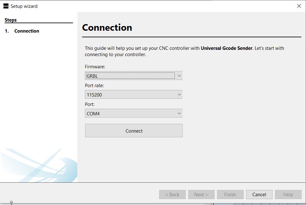
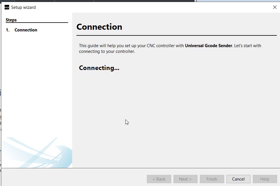
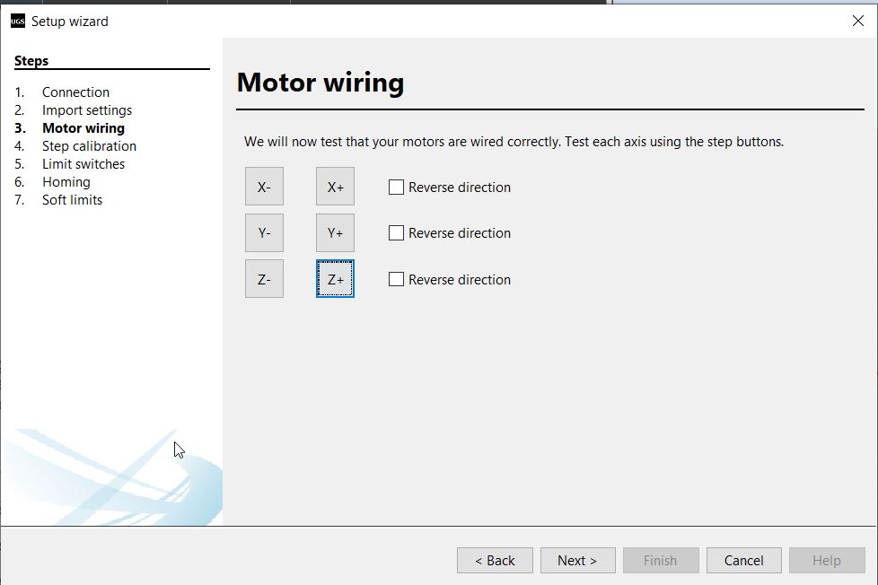
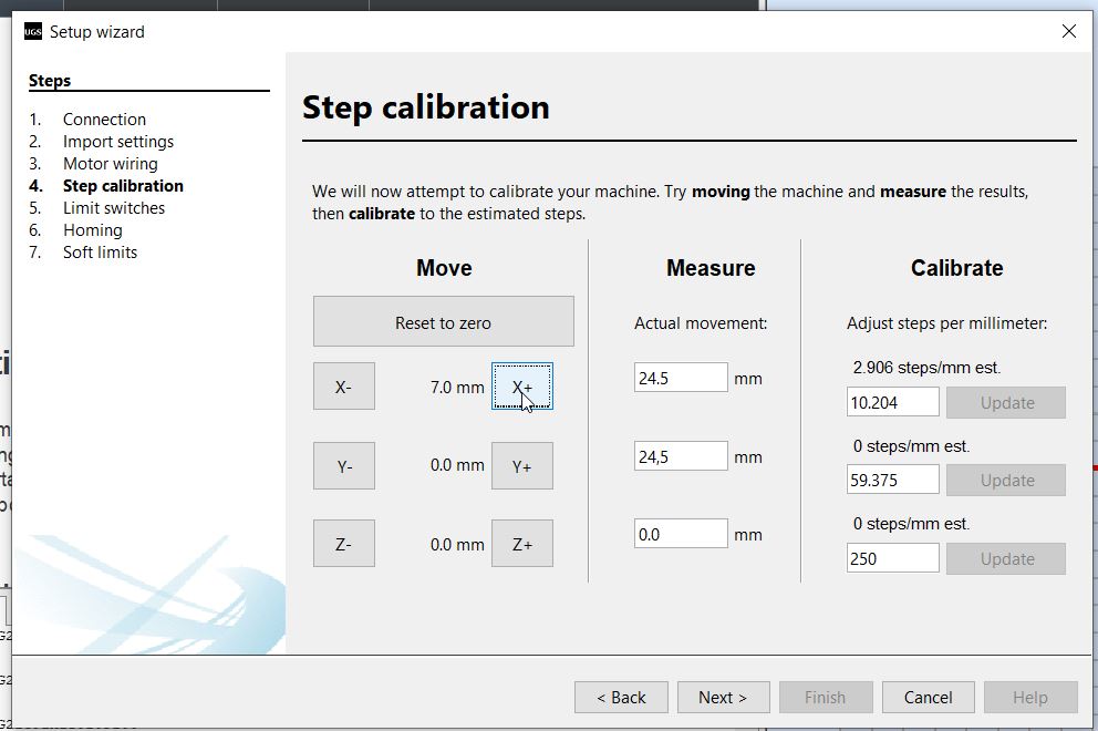
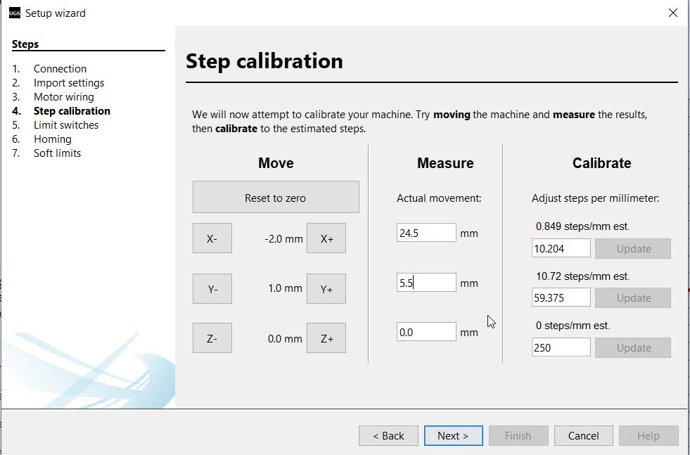
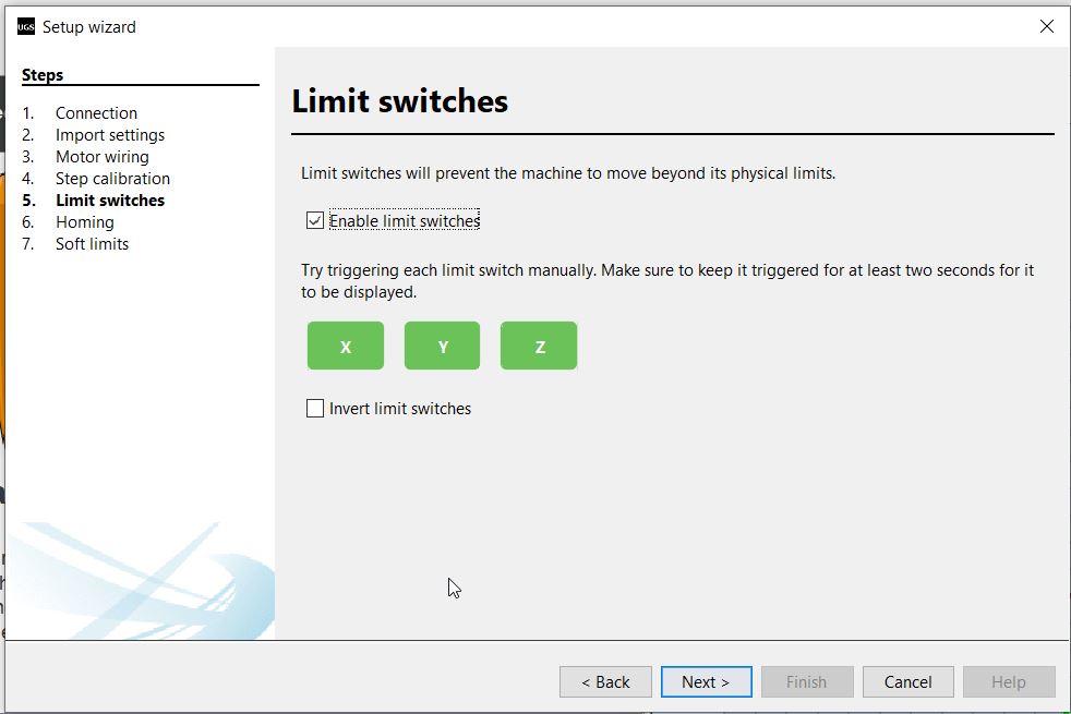
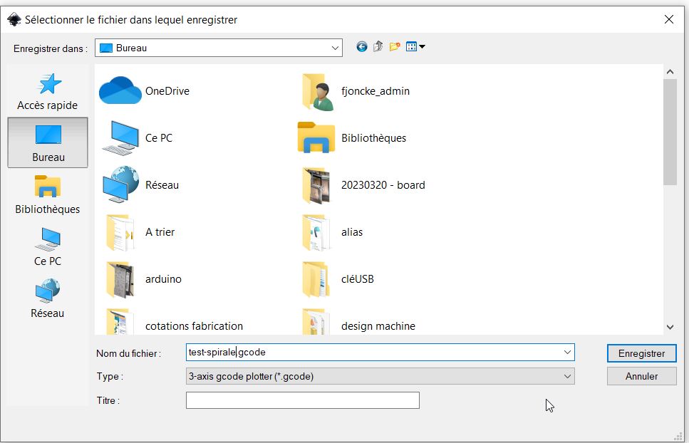
Universal Gcode Sender (UGS)
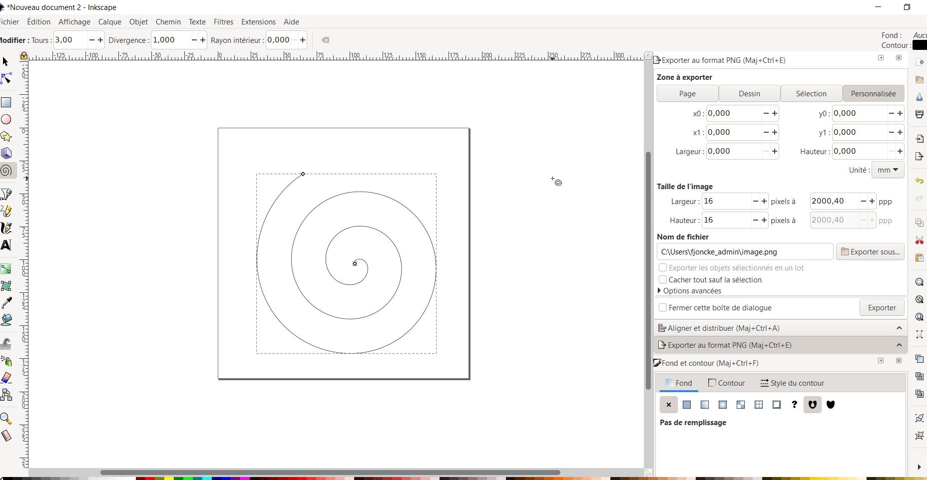
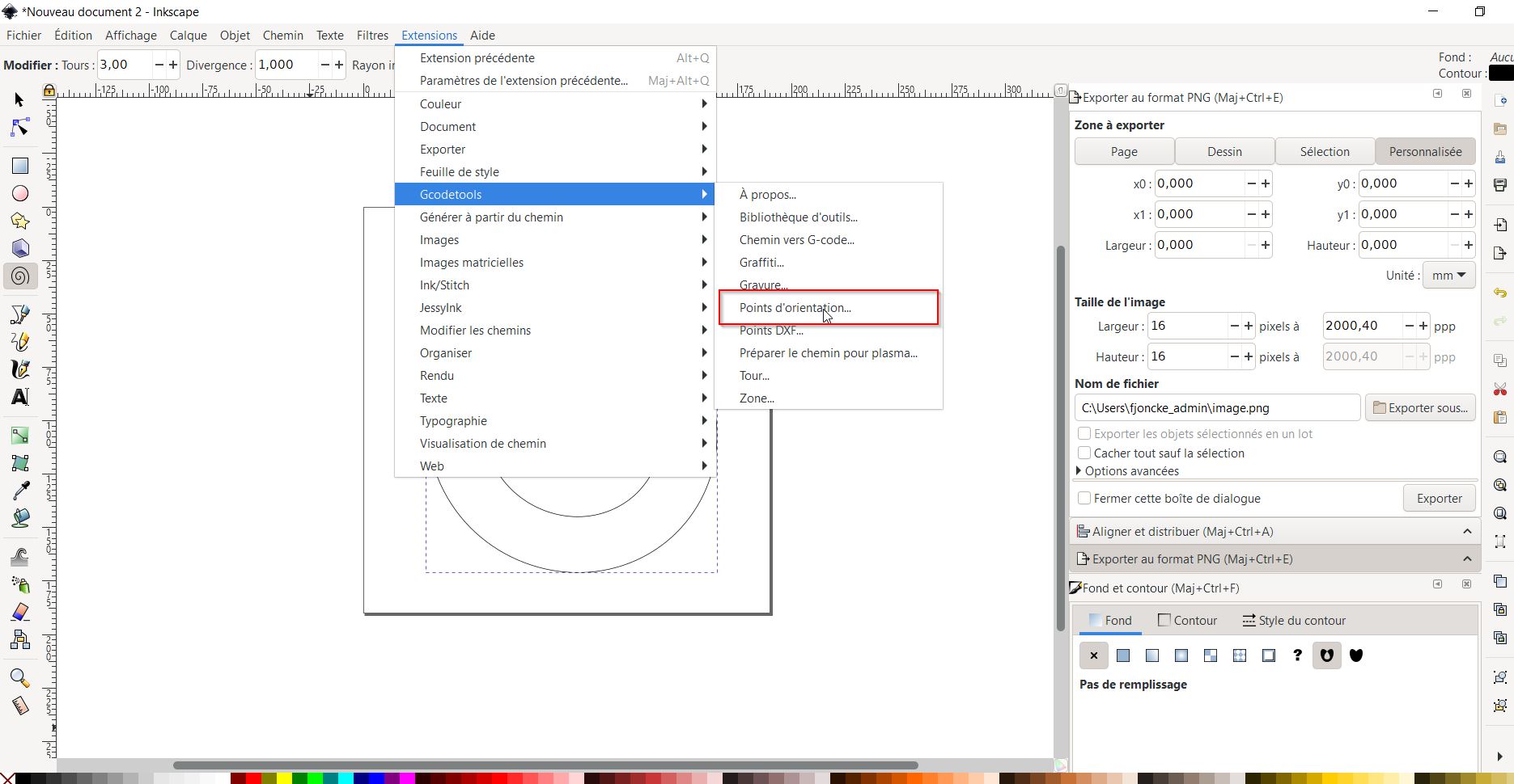
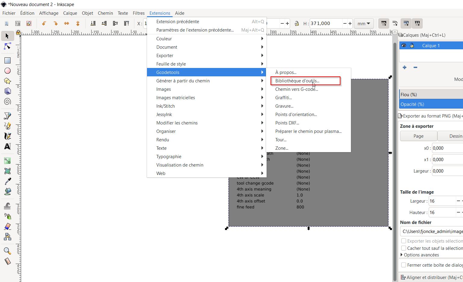
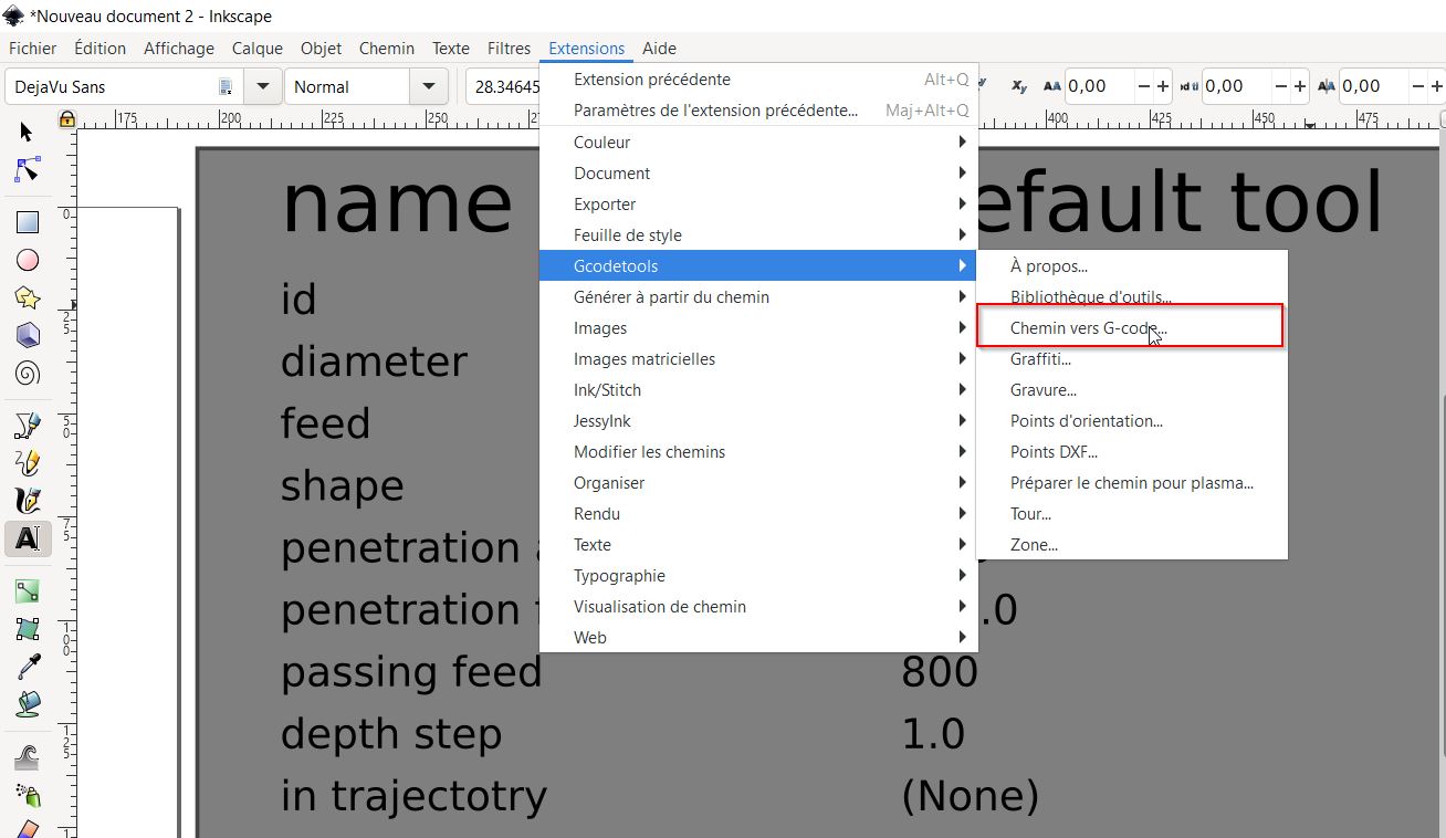
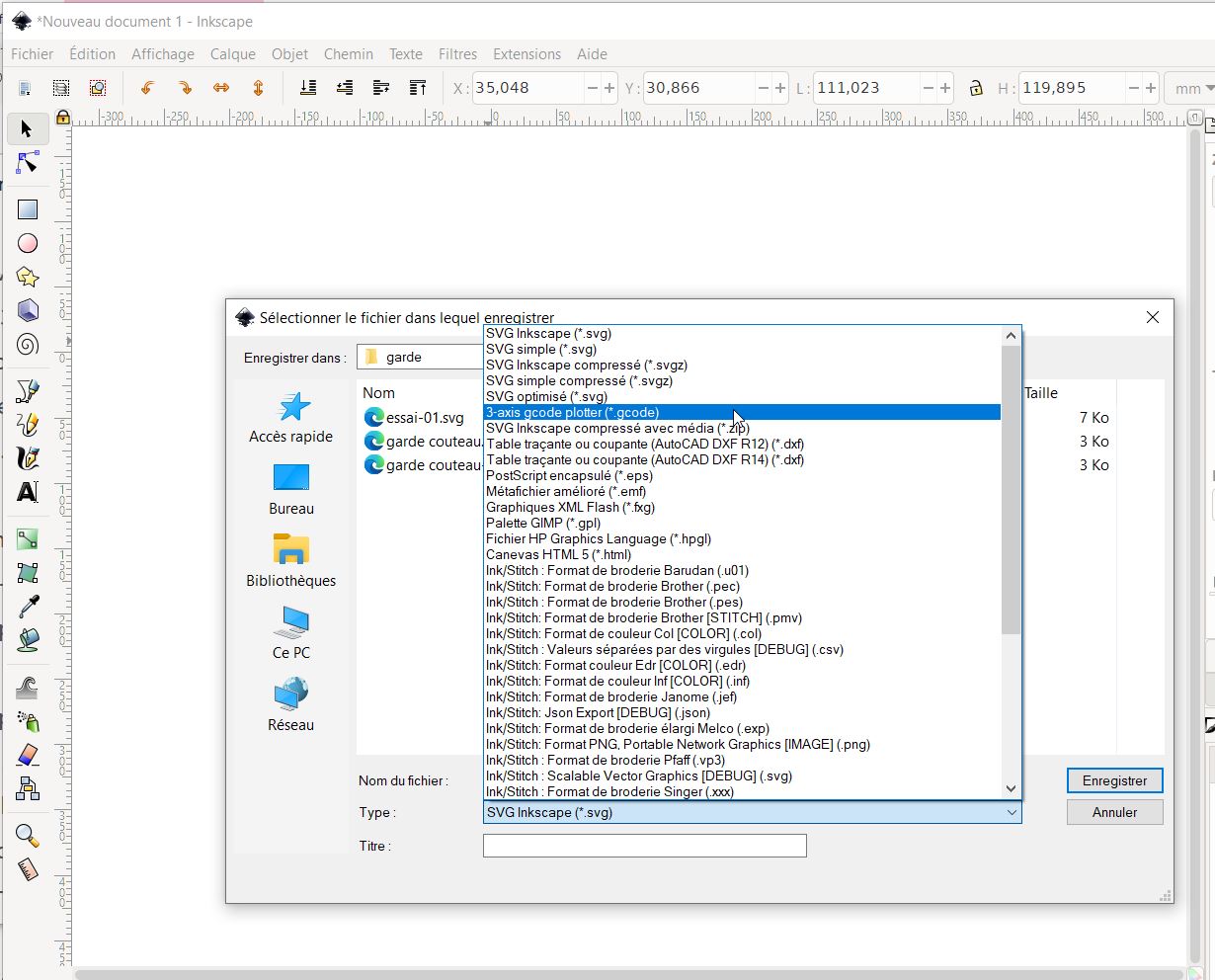
Inkscape
//////////////FAILED extensions for inkscape: 4XIDRAW
/////// UGS updated ==< it works>
Alimentation labo.
Useful links
https://www.instructables.com/Use-3D-Printer-As-a-Plottercutter/
- How to use writing machine - 2D Plotter Setup and Use Universal G-code sender -Pronterface
Inskcape extensions.
Grbl plotter - Google - Markdown
skf select.
IATE.eu translator
Code Example
Use the three backticks to separate code.
// the setup function runs once when you press reset or power the board
void setup() {
  // initialize digital pin LED_BUILTIN as an output.
  pinMode(LED_BUILTIN, OUTPUT);
}

// the loop function runs over and over again forever
void loop() {
  digitalWrite(LED_BUILTIN, HIGH);   // turn the LED on (HIGH is the voltage level)
  delay(1000);                       // wait for a second
  digitalWrite(LED_BUILTIN, LOW);    // turn the LED off by making the voltage LOW
  delay(1000);                       // wait for a second
}
Gallery

Video
From Vimeo
Sound Waves from George Gally (Radarboy) on Vimeo.
From Youtube
3D Models
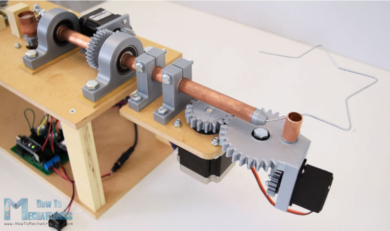
Building a wire bending machine
For this assignment, I joined my colleague Sylvain Robert and Jules Topart from La Machinerie. I am not used to build mechancial machine so I have followed them during the time of this assignement. Sylvain came with this idea: a wire bending machine. There are a lot on the web. We decided to get our own. The pandemic is still very active right now, and it is more difficult to go to La Machinerie. That’s why I am trying to work in the Fabricarium, but it is quiet difficult. Because the students there are asking me advices.
Sylvain showed me a lot of information about wire bending circuits:
-
this tutorial from Mecatronics:
 How-to-Mecatronics
 -
the artist: Mohit Bhoite. (Kind of funny because “boite” means box)
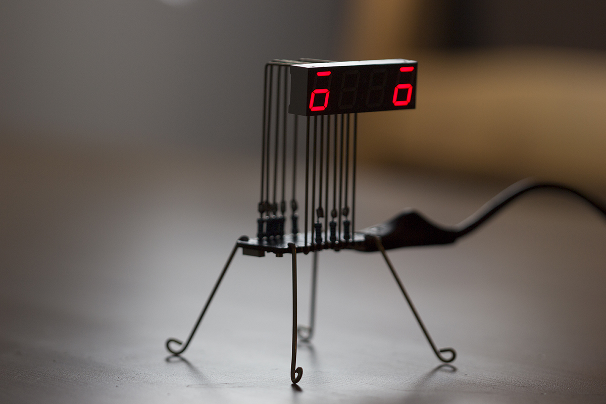 Mohit Bhoite ‘s website
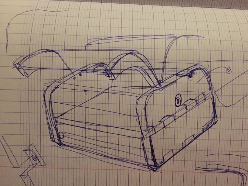
We had differents points of view about the building of the machine, Sylvain wanted to get the mechanism first, and then design the box.
For this project, I am a follower because they gave me a lot of knowledges.
If we are on time, we will think about the box.
Gears:
Sylvain, and other mechanichal colleagues explained me the building of the gearing.
https://www.cours-et-exercices.com/2016/03/cours-des-engrenages.html
module
Nema 17 stepper.
| parameters | specifications |
|---|---|
| dimensions | 92cm x 26cm x 26cm |
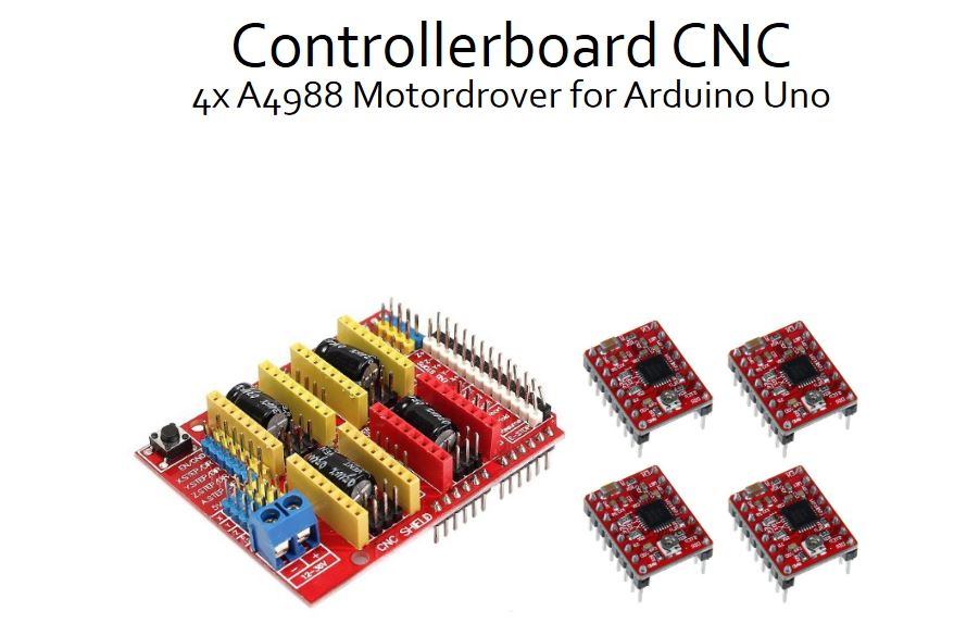
| ModelControllerboard | CNC with 4x A4988 Motordriver for Arduino Uno |
| Article | No.Com-CNC-Kit1 |
| Input Voltage | 12 -36V |
| Feature 01 | Detachable A4988 Motortreiber |
| Feature 02 | Compatible to GRBL 0.8 |
| Feature 03 | Control of up to 4 Axes |
| Feature 04 | Reset-Button |
| Feature 05 | Screw-Terminals for power supply |
| Compatible to | Arduino Uno |
| Dimensions (W x D x H) | 53 x 68 x 18mm |
| Scope of Delivery | CNC Controllerboard, 4x A4988 Motordriver |
| EAN | 4250236815961 |
Arduino & Nema 17 Go tronic, Arduino cnc shield datasheet Arduino & Nema 17 Arduino & cncshield Adjustment of the nema17 driver:
Nema17 works at 1,7A. current limit = Vref * 2,5 => 1,7 = Vref x 2,5 => Vref = 1,7/2,5
https://e3d-online.dozuki.com/Guide/VREF+adjustment+A4988/92
You need to install the cncshield library in the library folder of Arduno
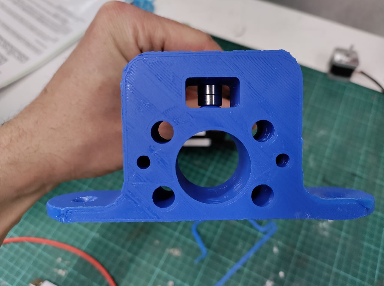
gear bearing
https://www.thingiverse.com/thing:53451
“Lorem ipsum dolor sit amet, consectetur adipiscing elit, sed do eiusmod tempor incididunt ut labore et dolore magna aliqua. Ut enim ad minim veniam, quis nostrud exercitation ullamco laboris nisi ut aliquip ex ea commodo consequat. Duis aute irure dolor in reprehenderit in voluptate velit esse cillum dolore eu fugiat nulla pariatur. Excepteur sint occaecat cupidatat non proident, sunt in culpa qui officia deserunt mollit anim id est laborum.”
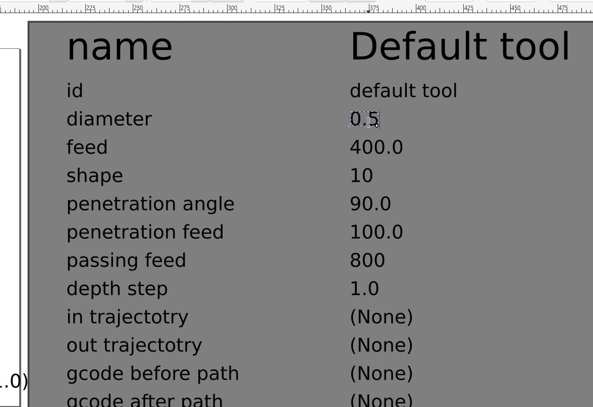
Understanding G-code:
G01 X247.951560 Y11.817060 Z-1.000000 F400.000000
The line has the following structure:
G## X## Y## Z## F##
First is the G-code command and in this case that’s the G01 which means “move in straight line to a specific position”. We declare the position or the coordinates with the X, Y and Z values. Lastly, with the F value we set the feed rate, or the speed at which the move will be executed.
To wrap up, the line G01 X247.951560 Y11.817060 Z-1.000000 F400 tells the CNC machine to move in a straight line from its current position to the coordinates X247.951560, Y11.817060 and Z-1.000000 with speed of 400 mm/min. The unit is mm/min because if we take a look back at the G-code example image, we can see that we have used the command G21 which sets the units to millimiters. If we want the units in inches, we use the G20 command instead.
G00 – Rapid Positioning
The G00 command moves the machine at maximum travel speed from a current position to a specified point or the coordinates specified by the command. The machine will move all axis at the same time so they complete the travel simultaneously. This results in a straight line movement to the new position point.
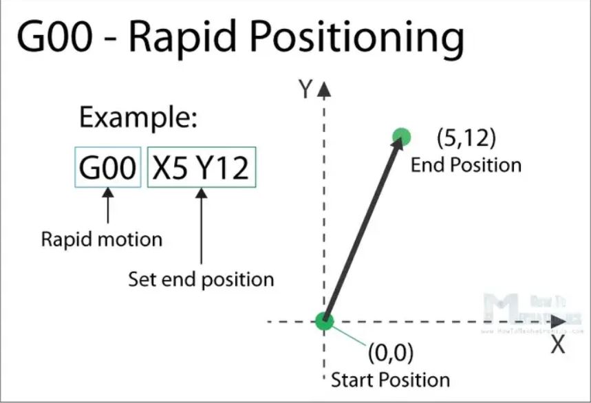 The G00 is a non-cutting movement, and its purpose is to just quickly move the machine to the desired position to begin some kind of job, like cutting or printing.
G01 – Linear Interpolation
The G01 G-code command instructs the machine to move in a straight line at a set feed rate or speed. We specify the end position with the X, Y and Z values, and the speed with the F value. The machine controller calculates (interpolates) the intermediate points to pass through to get that straight line. Although these G-code commands are simple and quite intuitive to understand, behind them, the machine controller performs thousands of calculations per second in order to make these movements.
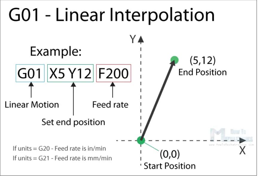 Unlike the G00 command which is used just for positioning, the G01 command is used when the machine is performing its main job. In case of lathe or mill, cutting material in straight line, and in case of a 3D printer, extruding material in straight line.
G02 - Circular Interpolation Clockwise
The G02 command tells the machine to move clockwise in a circular pattern. It’s the same concept as the G01 command and it’s used when performing the appropriate machining process. In addition to the end point parameters, here we also need to define the center of rotation, or the distance of the arc start point from the center point of the arc. The start point is actually the end point from the previous command or the current point.
For better understanding, we will add the G02 command after the G01 command from the previous example.
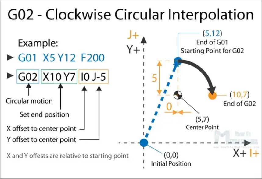 So, in the example first we have the G01 command which moves the machine to the X5, Y12 point. Now this will be the starting point for the G02 command. With the X and Y parameters of the G02 command we set the end point. Now in order to get to this end point using a circular motion or using an arc, we need to define its center point. We do that using the I and J parameters. The values of the I and J are relative to the starting point, or the end point of the previous command. So, to get the center point to the X5 and Y7, we need to make an offset of 0 along the X axis, and offset of -5 along the Y axis.
Of course, we can set the center point anywhere else, thus we will get a different arc which ends at the same end point. Here’s an example of that:
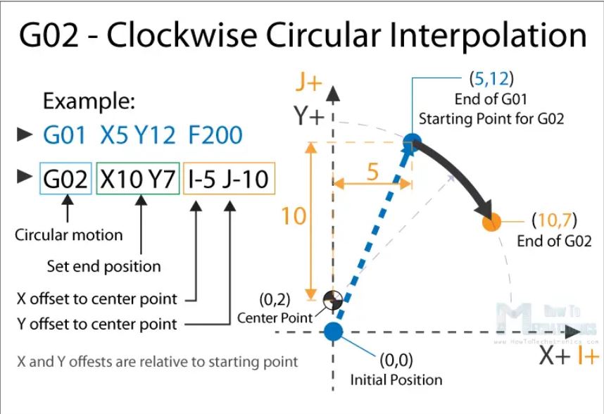 So, here we still have the same end point as the previous example (X10, Y7), but the center point is now at different position (X0, Y2). With this we got wider arc compared to the previous one.
G00, G01, G02 Example – Manual G-code Programming
Let’s take a look at a simple CNC milling example using these three main G-code commands, G00, G01 and G02.
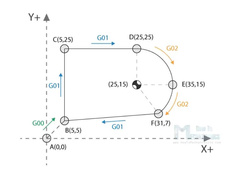
To get the toolpath for the shape shown in the image above we need to following G-code commands:
G00 X5 Y5                ; point B
G01 X0 Y20 F200          ; point C
G01 X20 Y0               ; point D
G02 X10 Y-10 I0 J-10     ; point E
G02 X-4 Y-8 I-10 J0      ; point F
G01 X-26 Y-2             ; point B
With the first G00 command, we quickly bring the machine from its home or initial position to the point B(5,5). From here we start with “cutting” at a feed rate of 200 using the G01 command. We can note here that for getting from point B(5,5) to the point C(5,25) we use values for the X and Y relative to the starting B point. So, +20 units in Y direction will get us to point C(5,25). Actually, this depends whether we have selected the machine to interpret the coordinates as absolute or relative. We will explain this in later section.
Once we reach the point C(5,25), we have another G01 command to reach the point D(25,25). Then we use the G02 command, a circular motion, to get to point E(35,15), with a center point (25,15). We actually have the same center point (25,15) for the next G02 command, to get to point F(31,7). However, we should note that the I and J parameters are different from the previous command, because we offset the center from the last end point or the point E. We finish the toolpath with another G01 command which gets us from point F(31,7) back to point B(5,5).
So, that’s how we can manually program the G-code for making this shape. Though, we need to note that this is not a complete G-code, because we are missing few more basic commands. We will make the complete G-code in a later example as we first need to explain those G-code commands.
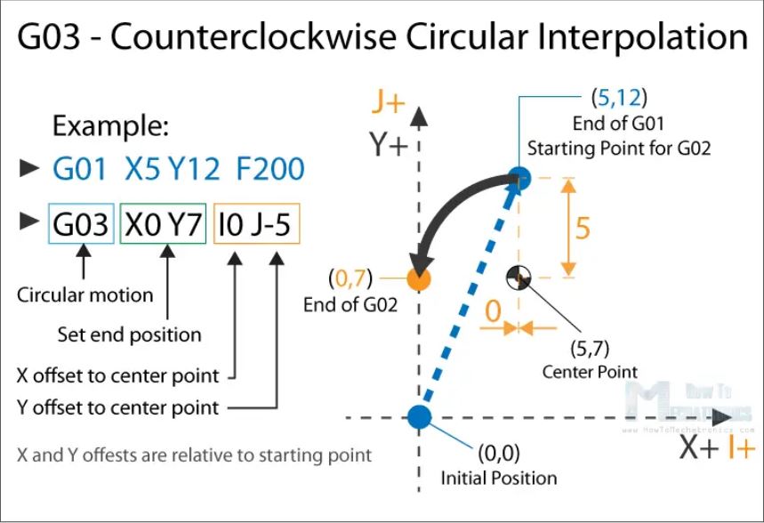
G03 – Circular Interpolation Counterclockwise
Just like the G02, the G03 G-code command defines the machine to move in circular pattern. The only difference here is that the motion is counterclockwise. All other features and rules are the same as the G02 command.
 So, with these three main G-code commands, G01, G02 and G03 we can generate a toolpath for, literally, any shape we want. You might be wondering now how is that possible, but that’s actually an easy task for a computer and a CAM software. Yes, it’s true we can sometimes manually make a G-code program, but most of the time we do that with appropriate software which far more easier and safer.
Nevertheless, now explain few more important and commonly used commands and at the end make a real G-code example.
G20/ G21 – Units Selection
The G20 and G21 commands define the G-code units, either inches or millimters.
G20 = inches
G21 = millimiters
We need to note that the units must be set at the beginning of the program. If we don’t specify the units the machine will consider the default set by the previous program.
G17/ G18/ G19 – G-code Plane Selection
With these G-code commands we select the working plane of the machine.
G17 – XY plane
G18 – XZ plane
G19 – YZ plan
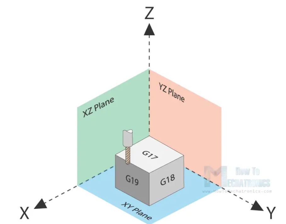
The G17 is default for most CNC machines, but the other two can be also used for achieving specific movements.
G28 – Return Home
The G28 command tells the machine to move the tool to its reference point or home position. In order to avoid collision, we can include an intermediate point with X, Y and Z parameters. The tool will pass through that point before going to the reference point. G28 X## Y## Z##
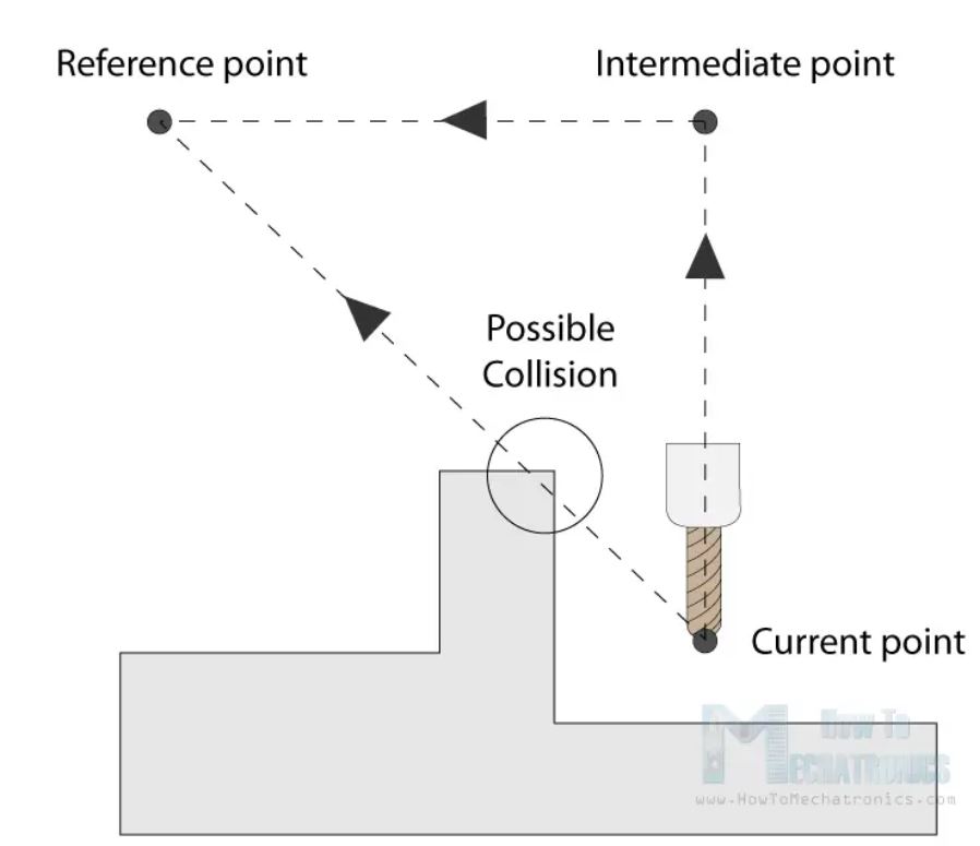
The home position can be defined with the command G28.1 X## Y## Z##.
G90/ G91 – Positioning G-code commands
With the G90 and G91 commands we tell the machine how to interpret the coordinates. G90 is for absolute mode and G91 is for relative mode.
In absolute mode the positioning of the tool is always from the absolute point or zero. So the command G01 X10 Y5 will take the tool to that exact point (10,5), no matter the previous position.
On the other hand, in relative mode G91, the positioning of the tool is relative to the last point. So if the machine is currently at point(10,10), the command G01 X10 Y5 will take the tool to point (20,15). This mode is also called “incremental mode”.
More Commands and Rules
So, the G-code commands we explained above are the most common ones but there are many more. There are commands like cutter compensation, scaling, work coordinate systems, dwell etc.
In addition to the G-code, there also M-code commands which are used when generating a real full-fledged G-code program. Here are few common M-code commands:
| Commands | functions |
|---|---|
| M00 | Program stop |
| M02 | End of program |
| M03 | Spindle ON clockwise |
| M04 | Spindle ON counterclockwise |
| M05 | Spindle STOP |
| M06 | Tool change |
| M08 | Flood coolant ON |
| M09 | Flood coolant OFF |
| M30 | End of program |
In case of a 3D printer:
| Commands | functions |
|---|---|
| M104 | Start extruder heating |
| M109 | Wait until extruder reaches T0 |
| M140 | Start bed heating |
| M190 | Wait until bed reaches T0 |
| M106 | set fan speed |
Some of these commands need appropriate parameters. For example, when turning on the spindle with M03, we can set the spindle speed using the S parameter. So, the line M30 S1000 will turn on the spindle at speed of 1000 RPM.
We can also note that many codes are modal, which means they remain in effect until cancelled or replaced by another code. For example, say we have a code for linear cutting movement G01 X5 Y7 F200. If the next movement is again a linear cutting, we can just type the X and Y coordinates, without the writing G01 at the front.
G01 X5 Y7 F200
X10 Y15
X12 Y20
G02 X5 Y5 I0 J-5
X3 Y6 I-2 J0
The same applies for the feed rate parameter F. We don’t have to include it in every line unless we want to change its value.
In some G-code file you can also see “N##” in front of the commands. The N word is simple to number the line or block of code. That can be helpful for identifying a specific line in case of an error in a huge program.
Simple G-code Program Example
Nevertheless, after reading all of this, now we are able to manually make a real, actual code. Here’s an example:
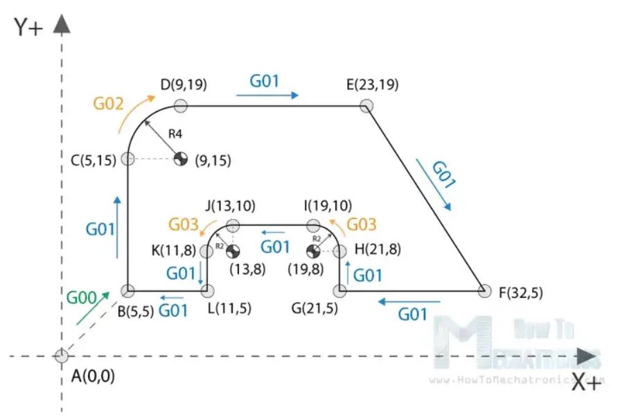
// Code initialization. This character (%)  is always present at the beginning and at the end of the program.
%
// Safety line: Set programming in metric system (all dimensions in mm), XY plane, absolute positioning and feed rate of 100 inches/min.
N01 G21 G17 G90 F100
N02 M03 S1000
N03 G00 X5 Y5                 ; point B
N04 G01 X5 Y5 Z-1             ; point B
N05 G01 X5 Y15 Z-1            ; point C
N06 G02 X9 Y19 Z-1 I4 J0      ; point D
N07 G01 X23 Y19 Z-1           ; point E
N08 G01 X32 Y5 Z-1            ; point F
N09 G01 X21 Y5 Z-1            ; point G
N10 G01 X21 Y8 Z-1            ; point H
N11 G03 X19 Y10 Z-1 I-2 J0    ; point I
N12 G01 X13 Y10 Z-1           ; point J
N13 G03 X11 Y8 Z-1 I0 J-2     ; point K
N14 G01 X11 Y5 Z-1            ; point L
N15 G01 X5 Y5 Z-1             ; point B
N16 G01 X5 Y5 Z0
N17 G28  X0 Y0
N18 M05
N19 M30
%
Description of the G-code program:
Spindle on clockwise at speed of 1000 RPM.
Rapid positioning to B(5,5).
Controlled motion on the same position, but lowering the tool to -1.
Linear cutting movement to position C(5,15).
Clockwise circular motion to point D(9,19), with center point at (9,15).
Linear cutting to point E(23,19).
Linear cutting to point F(32,5).
Same straight cutting to point G(21,5).
One more straight cutting to point H(21,8).
Counterclockwise circular interpolation to position I(19,10), with a center point at (19,8).
Linear cutting to point J(13,10).
Counterclockwise circular cutting to position K(11,8), with a center point at (13,8).
Linear cutting to position L(11,5).
Final linear cutting movement to position B(5,5).
Rise up the tool.
Go to home position.
Spindle off.
Main program end.
G90 absolute positioning G91 relative positioning G43 length tool compensation G81 drilling M30 End of program M03 clockwise spindle direction