In front of the digital fabrication, it is important to know the manual tool, to understand the “human gesture”.
MIG MAG(reminder)
This is not the purpose of this section, but it is important to know what the MIG-MAG is.
GMAW ( Gas Metal Arc Welding) MIG ( gaz neutre qui ne réagit pas avec le métal fondu (argon ou argon + helium))
[EN] from wikipedia: Gas metal arc welding (GMAW), sometimes referred to by its subtypes metal inert gas (MIG) and metal active gas (MAG) is a welding process in which an electric arc forms between a consumable MIG wire electrode and the workpiece metal(s), which heats the workpiece metal(s), causing them to fuse (melt and join). Along with the wire electrode, a shielding gas feeds through the welding gun, which shields the process from atmospheric contamination.
The process can be semi-automatic or automatic. A constant voltage, direct current power source is most commonly used with GMAW, but constant current systems, as well as alternating current, can be used. There are four primary methods of metal transfer in GMAW, called globular, short-circuiting, spray, and pulsed-spray, each of which has distinct properties and corresponding advantages and limitations.
[FR] depuis Wikipedia: La fusion des métaux est obtenue par l’énergie calorifique dégagée par un arc électrique qui éclate dans une atmosphère de protection entre un fil électrode fusible et les pièces à assembler. Les acronymes MIG et MAG signifient respectivement Metal inert gas et Metal active gas. La différence entre les deux procédés tient à la composition du gaz. Le procédé MIG utilise un gaz neutre qui ne réagit pas avec le métal fondu (argon ou argon + hélium), contrairement au procédé MAG (mélange d’argon et de dioxyde de carbone ou dioxygène en proportions variables selon les métaux à souder). Le gaz est injecté en continu sur l’arc afin d’isoler complètement le métal en fusion de l’air ambiant.
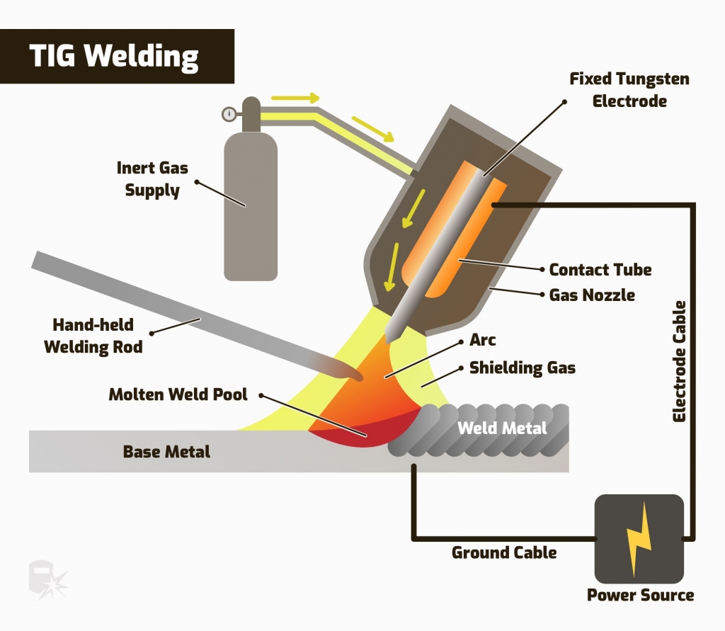
TIG (Tungsten Inert gar) or GTAW Gaz Tungsten Arc Welding.
Process
From weldguru.com
*TIG, or tungsten inert gas, uses a non-consumable tungsten electrode to create an arc and join metal. It requires the use of shielding gas, most commonly pure argon or argon mixed with helium.
This welding process uses direct current (“DC”) and alternating current (“AC”) depending on the metal to be joined.*
[FR] N° iso 141 metal apport.
N° iso142 sans metal d’apport
Fonctionne mono 220 V ou tri 380 v
facteur de marche tension à vide: 120A 100% Tension à vide 50 V
Reseau electrique generateur poste à souder. gaz inerte argon, mano detendeur, bonne sortie de gaz
torche tig.
masse.
Safety equipment (EPI)
gants en cuir avec manchette. veste en cuir ou tablier pour couvrir les bars. chaussures de secu casque automatique. mini une cellule avec 3 / 4 capteurs: tig fait des arcs electriques plus fin, il faut des cellules plus fines.
welding station
MATRIX 2200 AC (Centrale Lille)
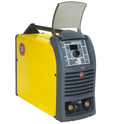
Powerful and lightweight, the MATRIX 2200 AC/DC represents the most innovative, efficient and technologically advanced single-phase inverter generator on the market. The digital control, immediately understandable and with advanced functions, guarantees the absolute stability of all the welding parameters and high quality welds, both in TIG and in MMA, including with a cellulosic electrode. It represents the ideal solution for all production welding applications and maintenance work, requiring both power and portability. The MATRIX 2200 AC/DC can TIG weld stainless steel, carbon steel, copper and aluminum and understands alloys.
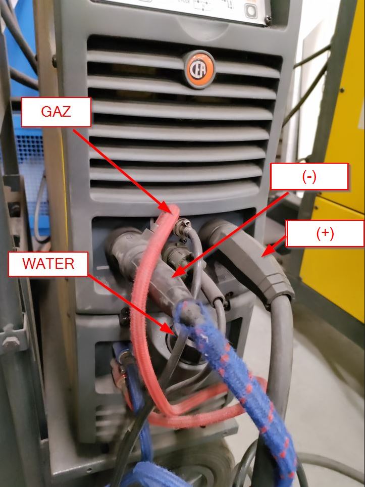
220 V monophase. STEEL : argon flow : 9L/min.
According to the station, You have to plug the differents tools such as Ground (-) the torch (+). Options such as watercooling and a current control pedal are available.
| Brand | model: |
|---|---|
| dimensions | 52 x 45 x 43 cm |
| Positioning accuracy : | 0,005 mm axis Z and 0,012 mm axis X and Y |
| Auto-leveling: | BL Touch® sensor , 9 levelings |
| Printing dimensions: | 25 x 25 x 25 cm, 15,6 L volume. |
| Printing speed : | 30 à 100 mm/s |
| Nozzle : | 0,4mm |
| Material : | PLA ABS, PETG, TPU, PVA |
| Hot bed : | 25 x 25 cm – 240W - maximum température: 110°C |
manual trigger(2times) Automatic trigger (four times)
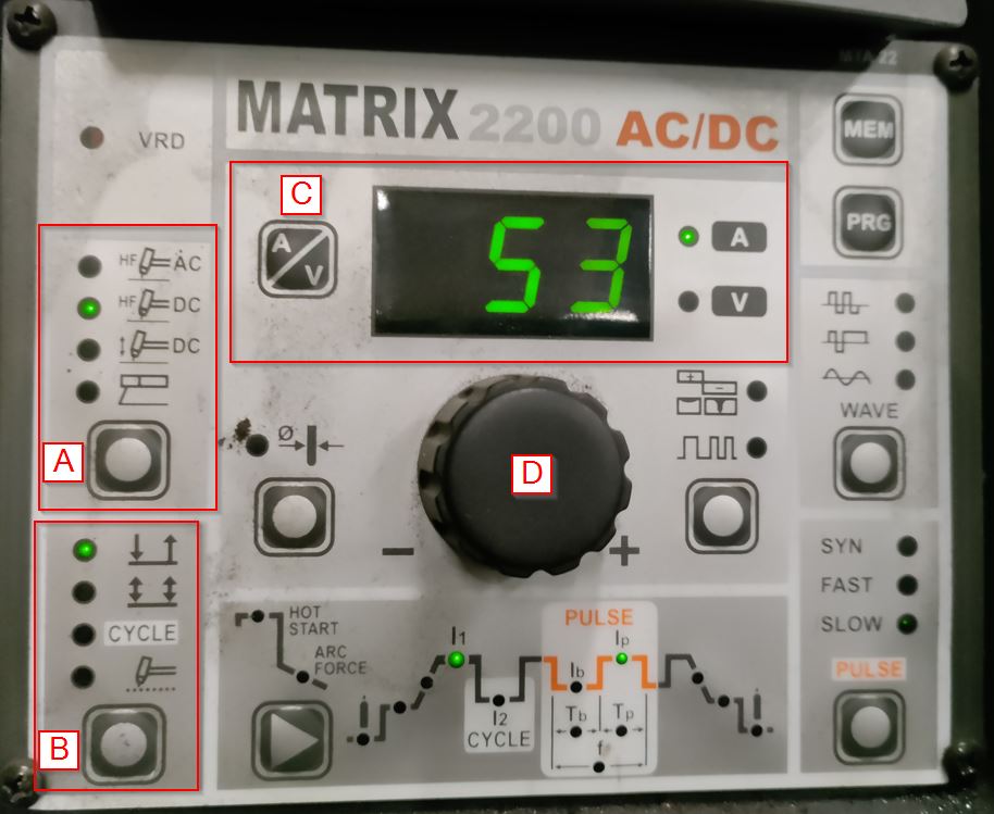
| Letter | function: |
|---|---|
| A | AC = Alternative Current // DC= Direct Current (pointing and welding// MMA |
| B | 1. 2 times // 2. 4 times |
GAZ
Argon AR garantit une parfaite qualité du cordon de soudure.
| type | composition | Soudure | matériaux | Applications |
|---|---|---|---|---|
| ARCAL PRIME | AR >99.998% | TIG | ACIER-INOX-ALU | convient à toutes les épaisseurs |
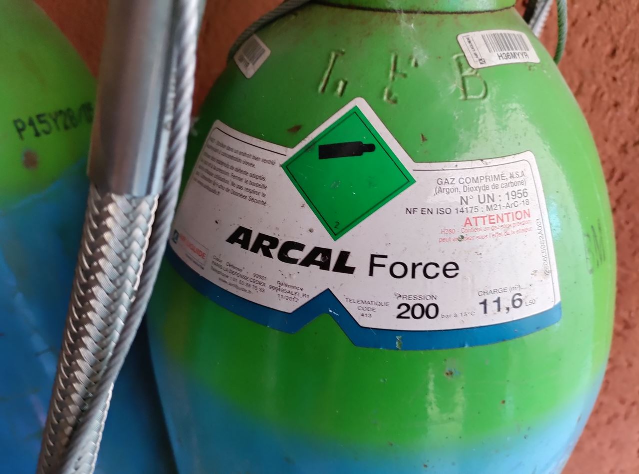
| ARCAL FORCE | AR - 18% Co2 | MAG | ACIER-INOX | convient à toutes les épaisseurs principalement forte épaisseurs |
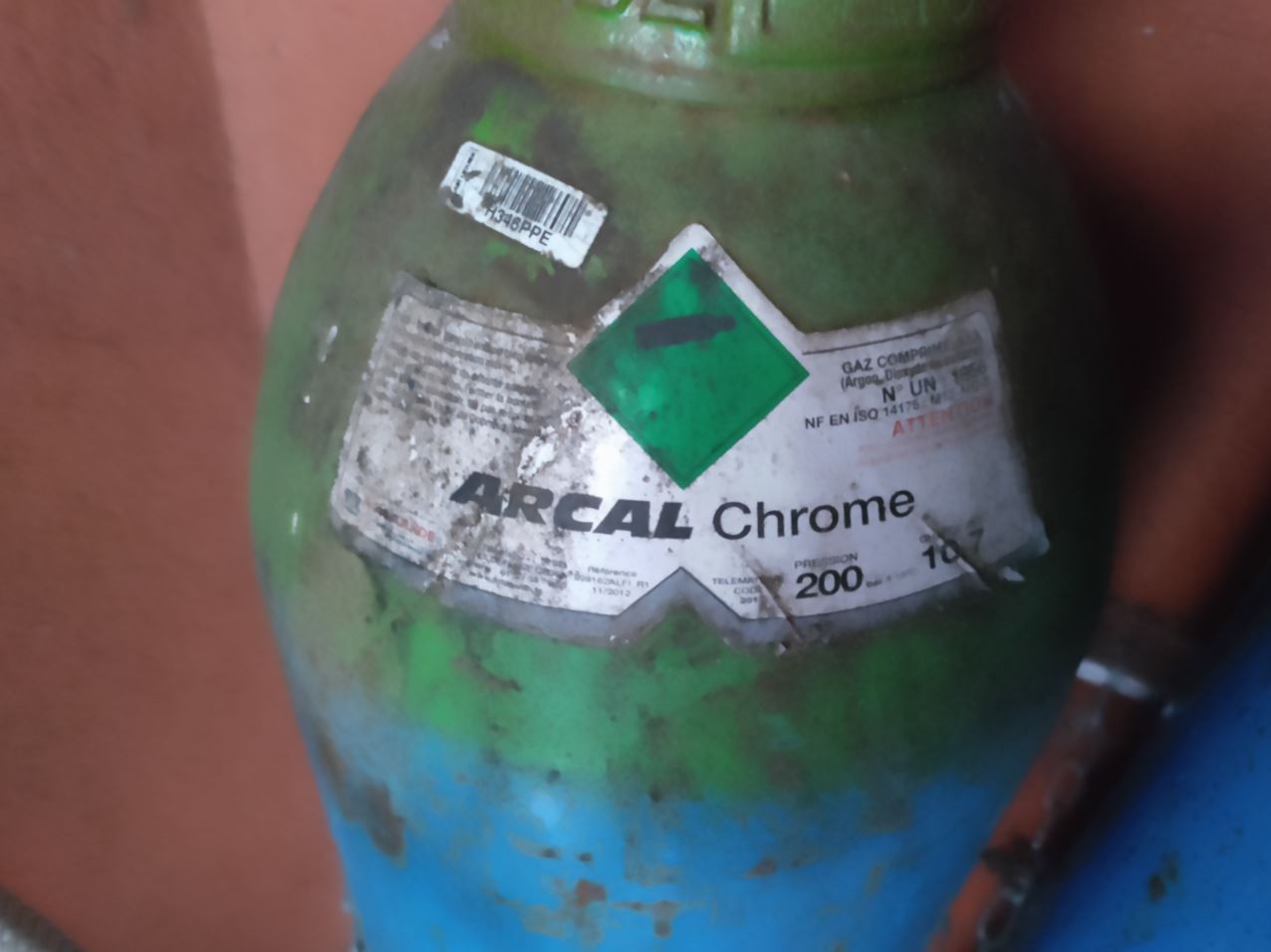
| ARCAL CHROME | AR - 2% Co2 | MIG | ALU | convient à toutes les épaisseurs |
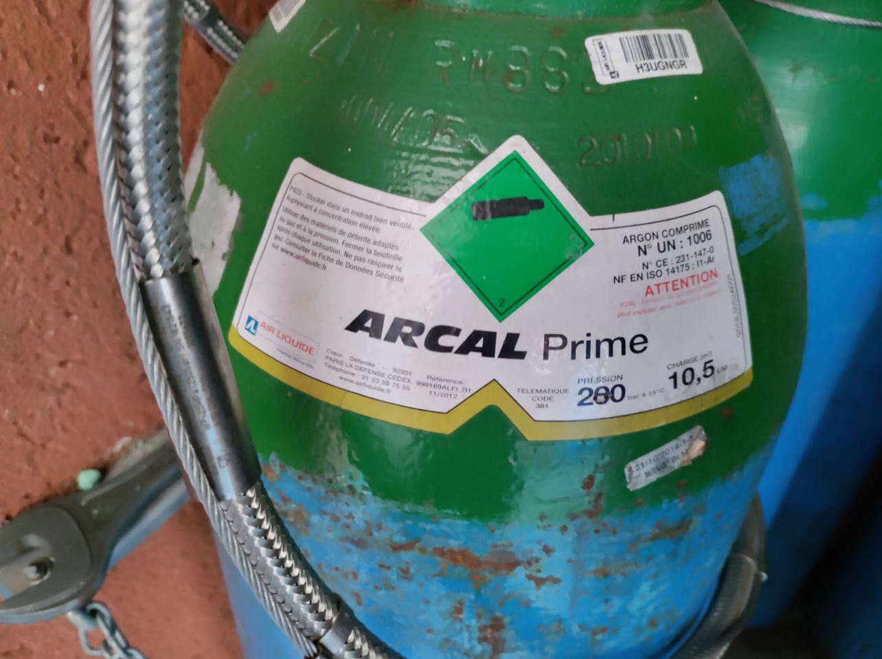
ARCAL Prime: TIG ACIER INOX ALU (laiton?) selon
Arcal force -AR -18% Co2 mag acier inox
chrome mig alu.
Gaz: Argon (Ag) 98% // (CO2) 2% MIG process will use the same gaz.
Alternative Current :Aluminium, 660 et 700 c
laiton.base cuivre et zinc( 800 900 °c)
Les adjuvants
Direct Current: steel(Base Fer + carbone C) T° fusion: 1450/1550°c , Inox (Fe C en faible quantié.+ nickel chrome> 10.5%, t fusion:1400)C faudra descencre l’intensité. Tcuivre: 900 /1000 c.
Inox from 1 to 4 mm TIG. Up to 4mm, MIG.
Get prepped for welding:
Dépourvu de gras, rouille, peinture, revetement (galva, electro zinguage, pelleilctule à retirer.)
Aluminium: ne pas utiliser du soctoch brite our utiliser grattoir ou brosse metalique dedies.
Acier: soctch brite ou tolemerie, disque à lamelles.
inox: degraissage, pas de corrsion, peinture, ni reveneemtnet: simplement alcool à bruler our acetone.
laiton: meme chose:
cuivre: scotch brite.
metal d’apport,
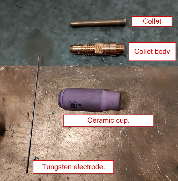
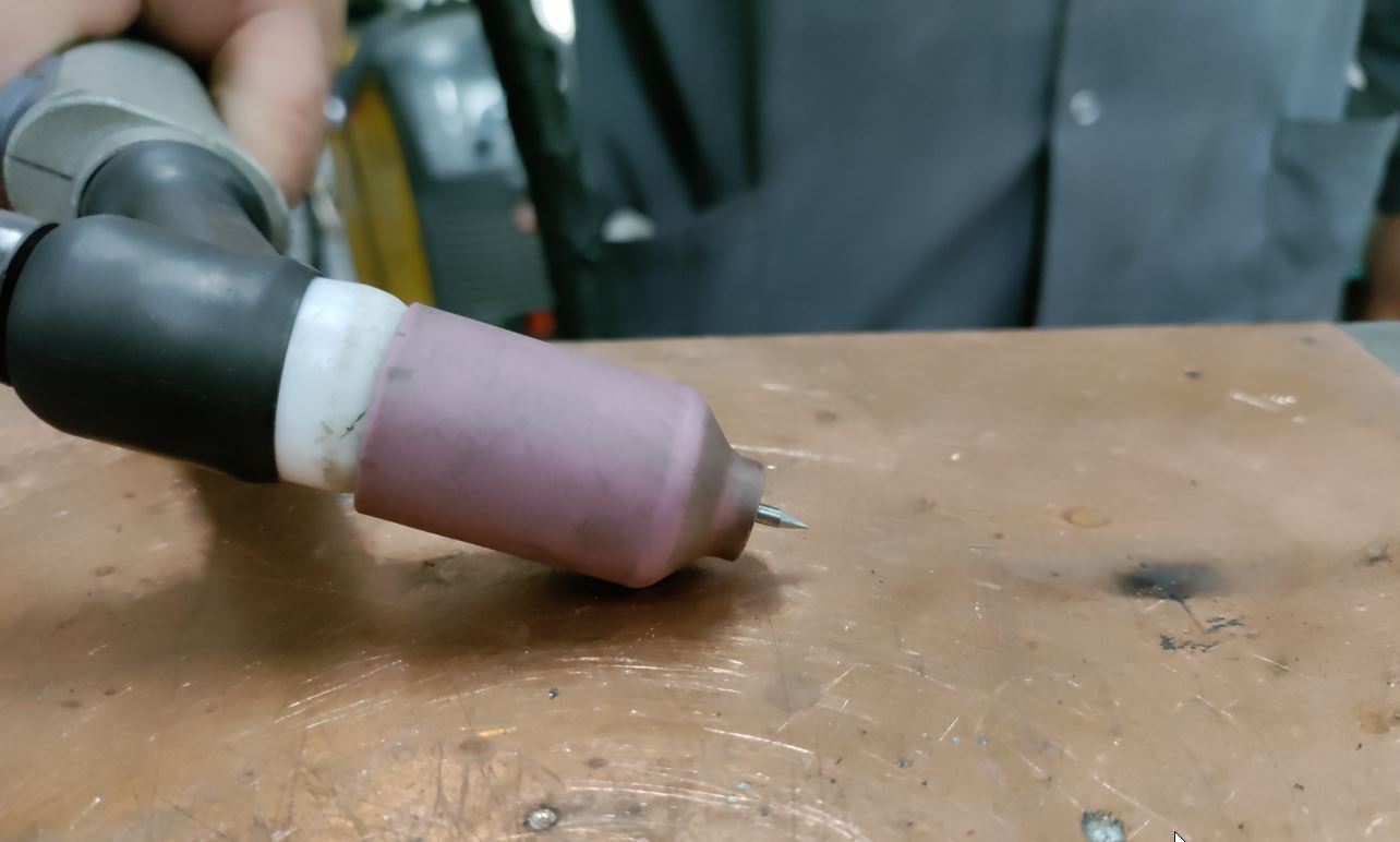
anatomy
What I have for my training:
Tungsten fond à 3500 degèrs
partie blanche bague d’étanchéité: isolation elect et etancheité gaz
porte tungstène (mandrins)
diffuseur
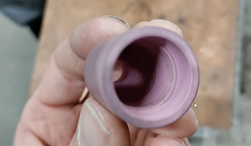
buse céramique. réfractaire, permet dans les fortes températures que le diam et la forme ne bouge pas
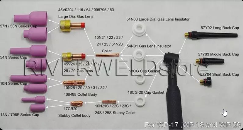
Stainless steel needs more gaz protection. large diam gaz lens (fr tamis)
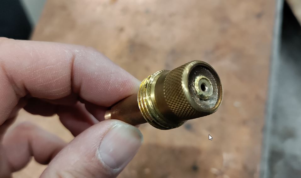
The ceramic cup is threaded.
coiffe. partie stylo.
connecteur 13 ou 9 mm diam sup pour faire passer le gaz. connection gaz. connection gachette.deux utiliés pour le contacteur . passage d’eau pour refoirid la torchage ou monter en ampérage.
GND 9mm ou 13mm quart tournant. sur (+)
electrode sur le moins.
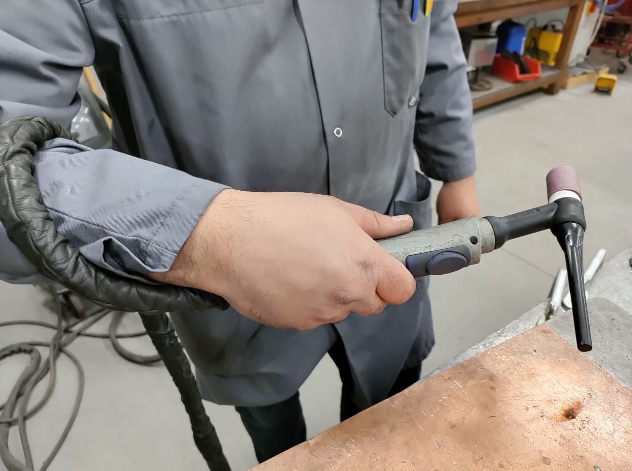
Working positions:
Advantages:
good esthetic.
Drawbacks:
High temperatures.
Current Rules:
Current (Amps) = ratio * Thickness
According to your welding results, ratio is around 30 - 40.
Example: for 2 mm thickness : 2 x 30 = 60 Amps
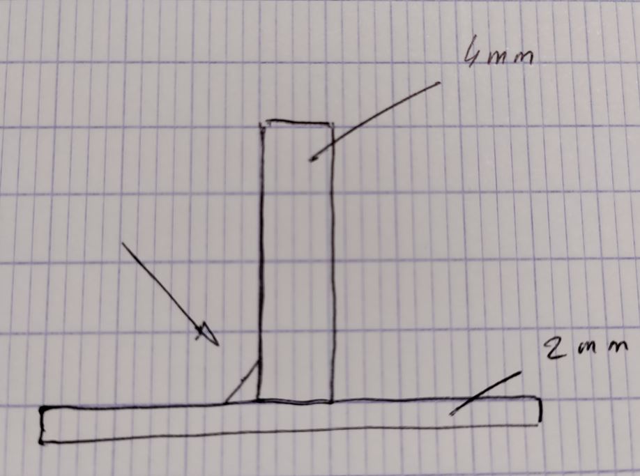
N.B we will increase current to make a 90° assembly.
Electrodes
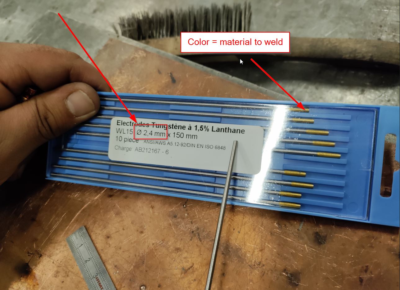 Different colors:
Green Alu Yellow stainless steel (fr Inox)
lanthane ne se casse pas facilement, résiste au courant electrique.
We have a range of electrode diameter.
1 - 1.6 - 2.4 - 3.2 mm
We will weld a 2 mm steel sheet, so we have the choice to 1.6 or 2.4 mm.
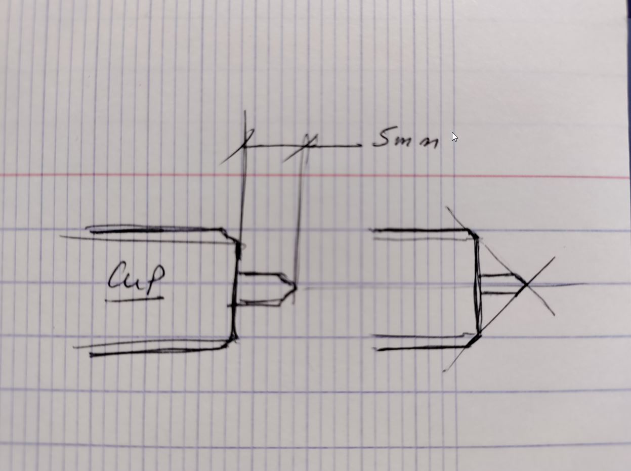
Electrode Sharpener:

30 degrès 45 egrès. 60 and 90 degrès.
Presentation of the device:
différence entre mig et mag/ pas le meme gaz: Mig gaz inerte ne réagit pas avec le metal fondu et sert surtoutà protéger le bain de fusion: argon ou argon/helium ou helium pure. IMportance esthétique du cordon.
MAG base Argon avec gaz actifs: co2 et/ou o2. Les gaz oxydants vont créer des oxydes en surface dits emissifs: ils vont falicilter la sorite des électrons et donc contribuer à la stabilité de l’arc elecrique.
Aciers inoxydables: ar-co2 ou ar-O2. IL ne faut pas oxyder le chorme.
acier: Ar-co2, ar-o2 ou ar-co2-O2
Premières soudure acier:
mettre la masse à la fin du cordon. support en cuivre, pour absorder energie, eviter de souder sur l’etabli. Cela absorbe de l’energie.
tige enrobée de cuivre pour éviter la rouille. tige plus fine que l’epaisseur à souder. 3mm faire un chamfrein.
pointage plus costaud.on augrmente de 10 à 20 A . pointage milieu puis extrémités. laisser le gaz refroidir le pointage.
si on utilise

On peut affûter sur différentangles 90 - 60 degrès
Cela joue sur le cordon.
Si on doit souder une pièce de 4mm avec une autre d e2mm,paramétrer le poste à souder il faut se rapprocher de la plus grosse pièce.
There is a particular way to move the torch, It reminds me when you want to move a barrel.
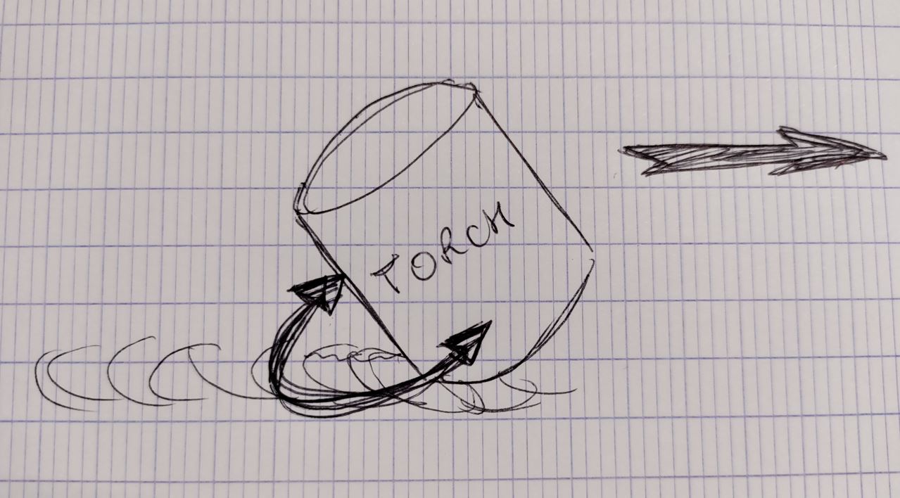
tig12.jpg tig13.jpg tig-14-traces.jpg
Gaz parameters:
IT depends on the diamèter of the ceramic cup.
Acier: 6 - 9 L/min Inox: 9 - 12 L/min.
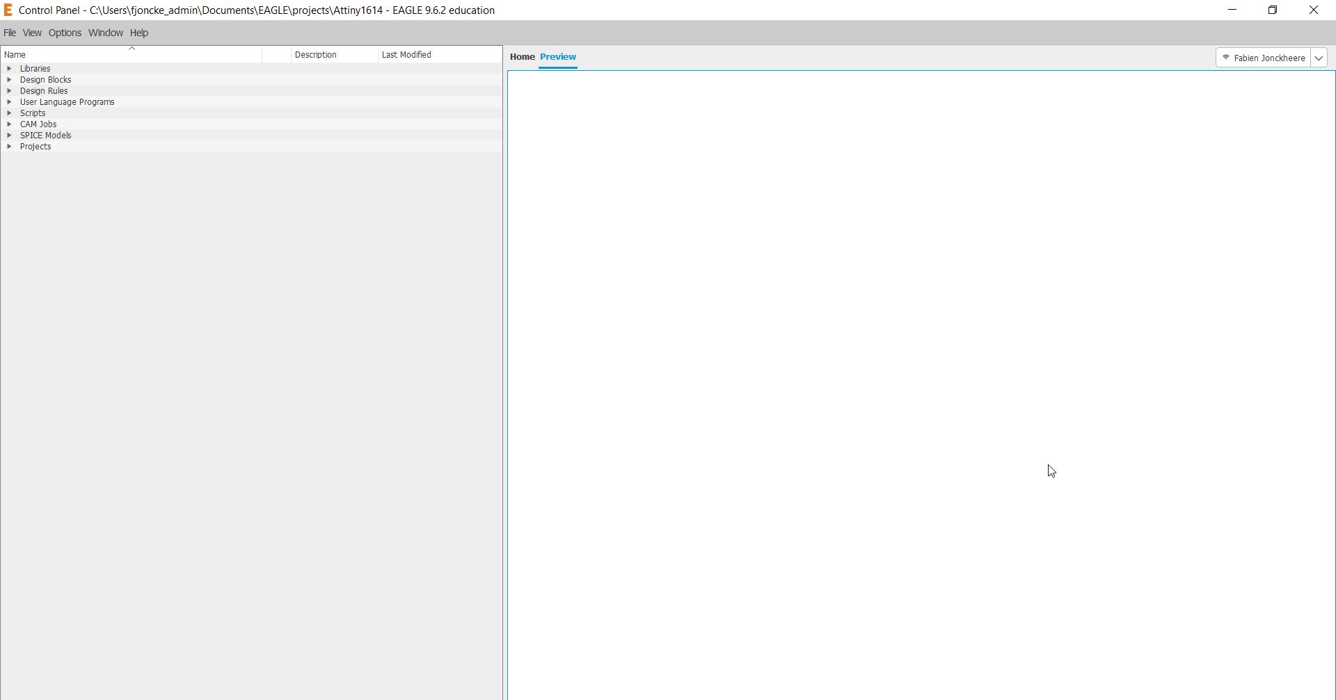
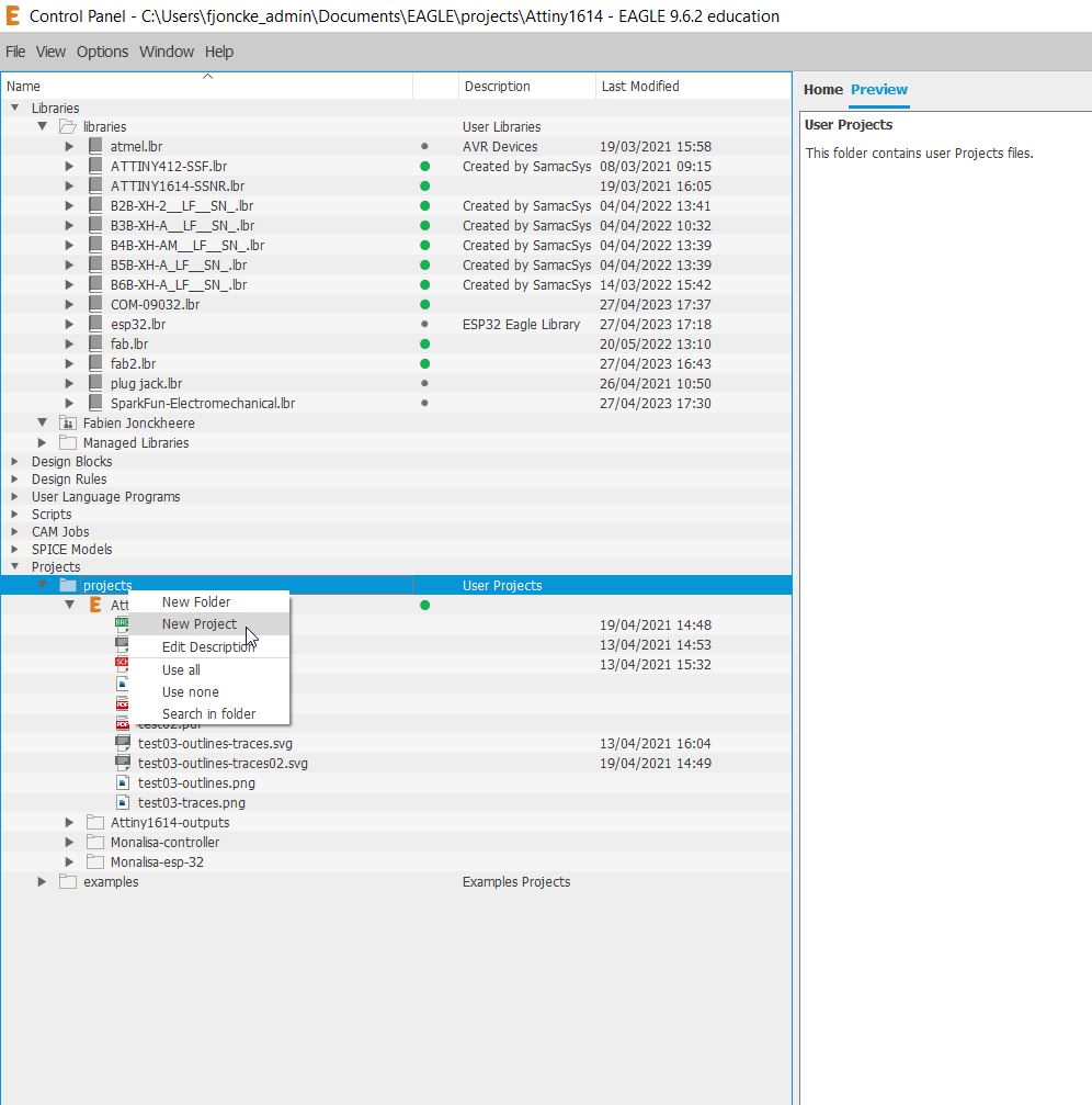
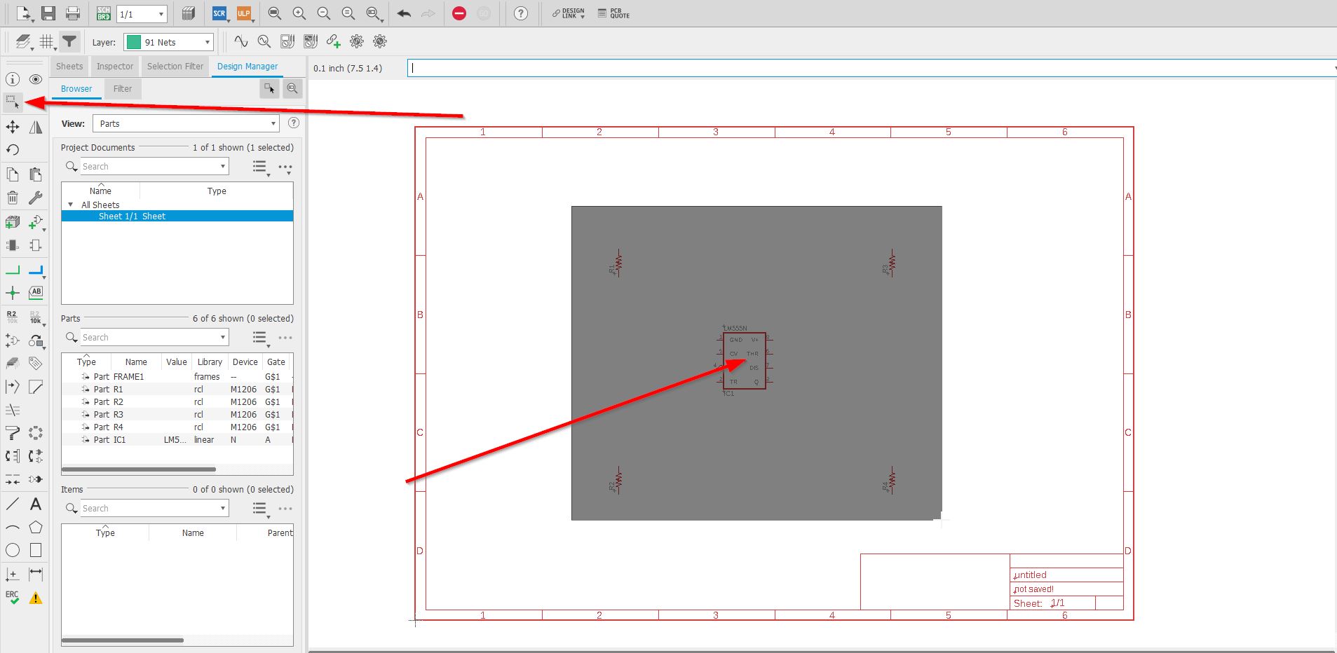
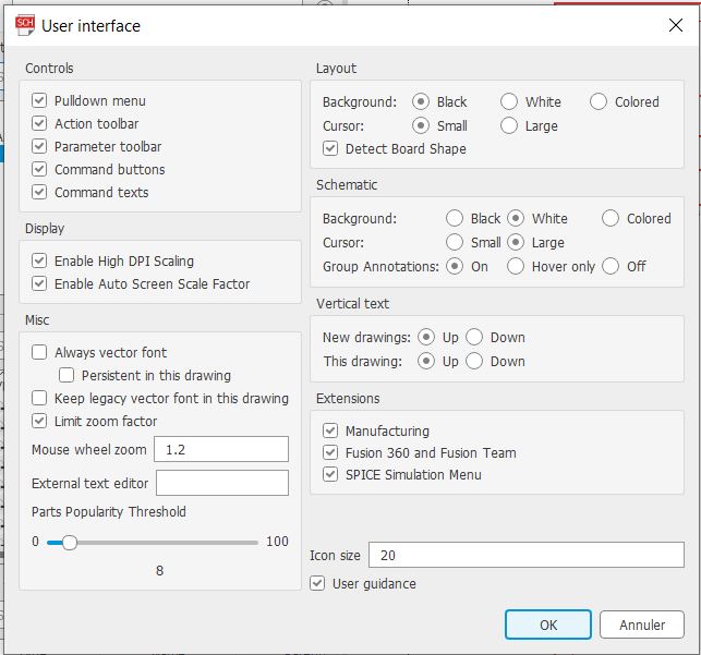
You open the software you will face the control panel. It is full of different stuffs important to activate before.
THere are the libraries organized by local, cloud datas.

You have the design blocks. Electronics brands such as adafruit, sparkfun have created a lot of electronics blocks ready to add on your projects. You also can create your own design blocks.
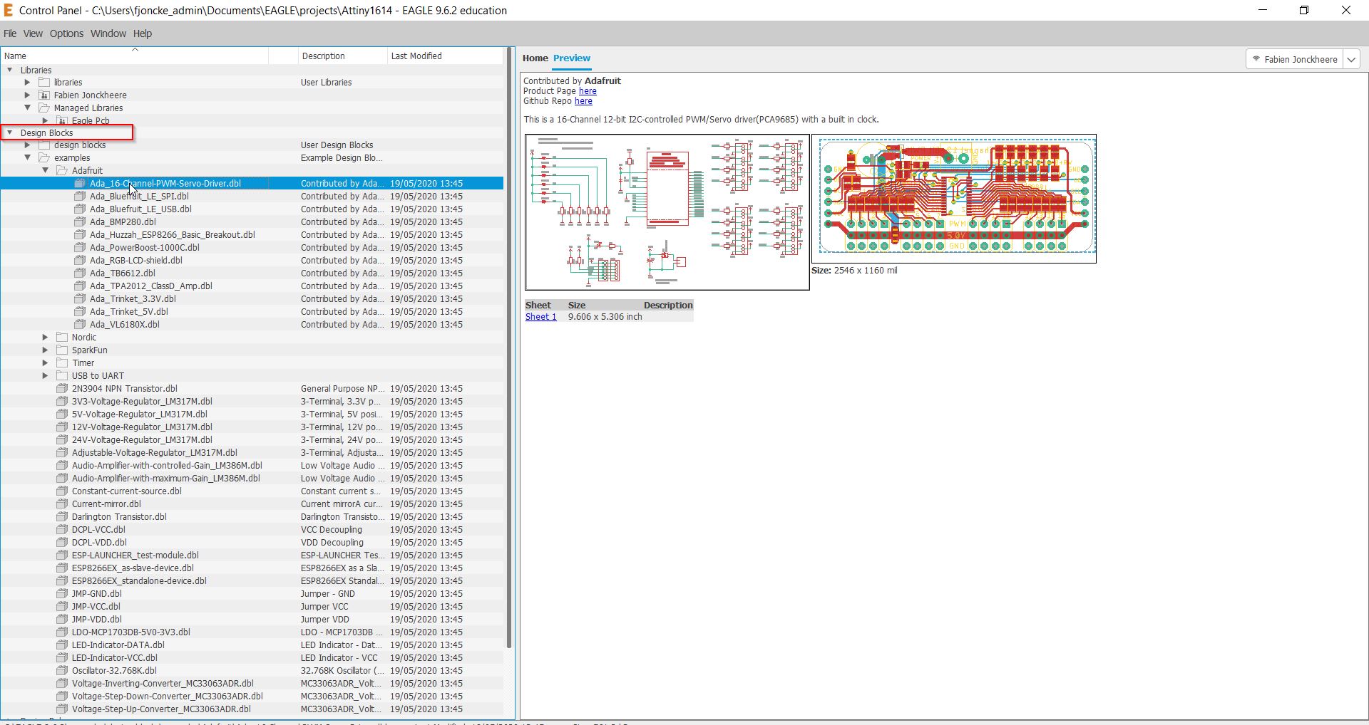
It is easy to get messy if you have everything available, that is why the green light show the availibility or not when you will work on your schematic.
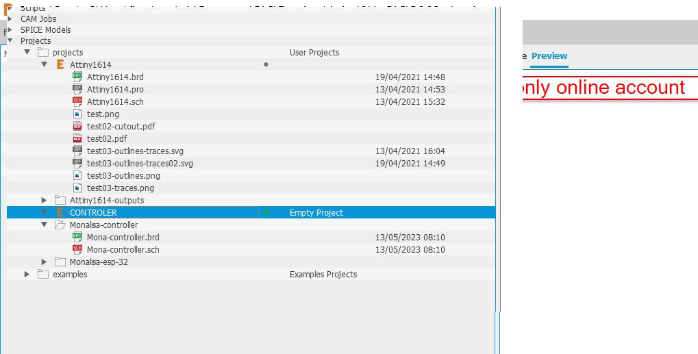
Go to project, and right click to create a new project.
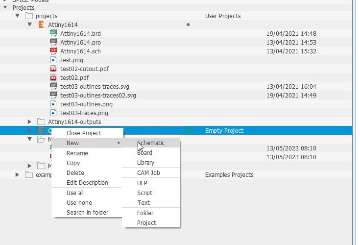
Simply right click and create a new schematic.
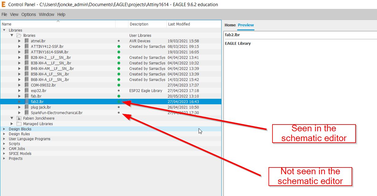
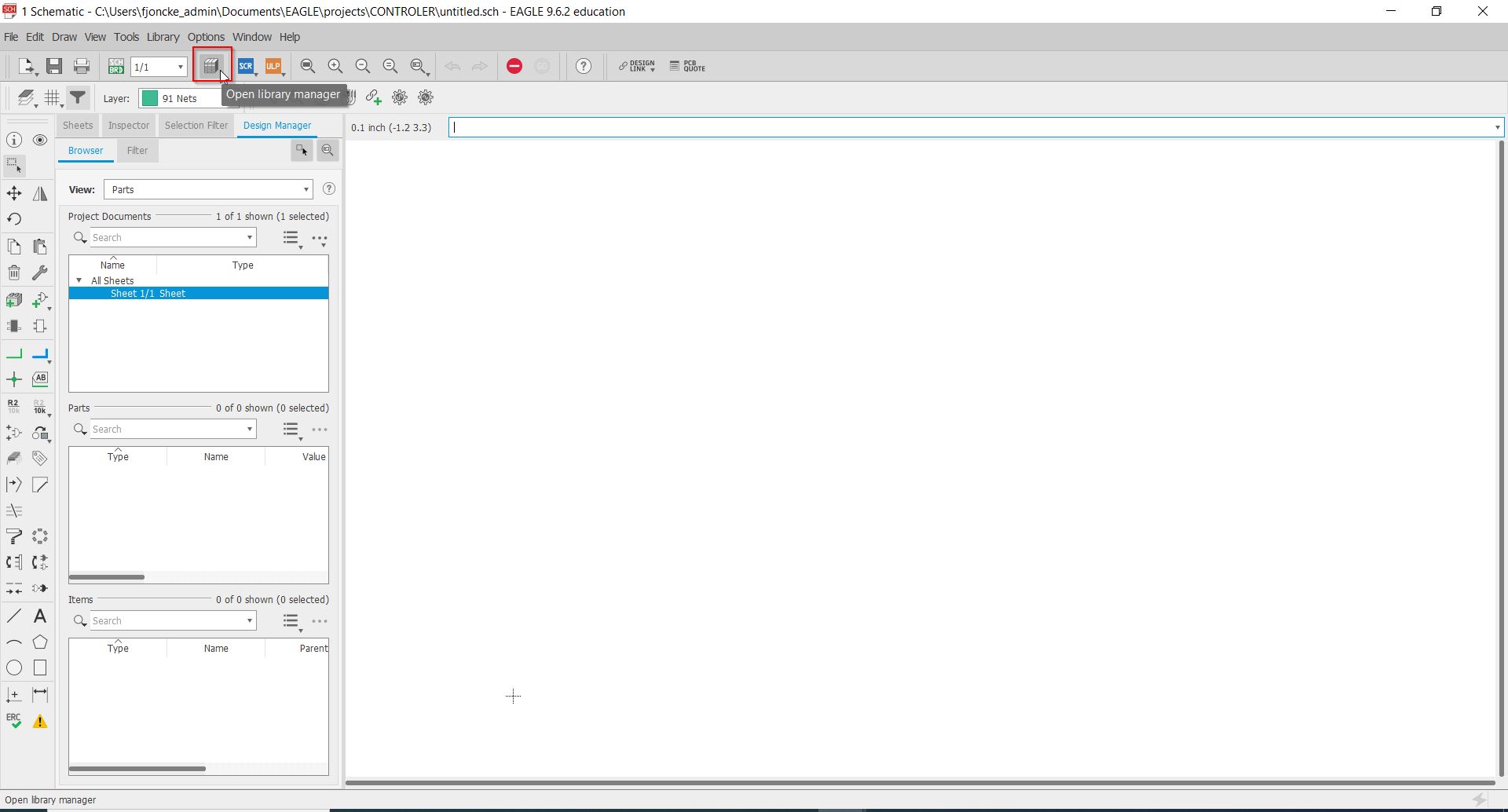
On the schematic panel, you will also have the editor of the libraries. And you can see the libraries highlighted in green in the control panel.
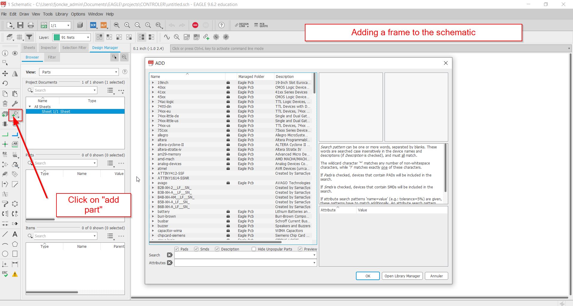
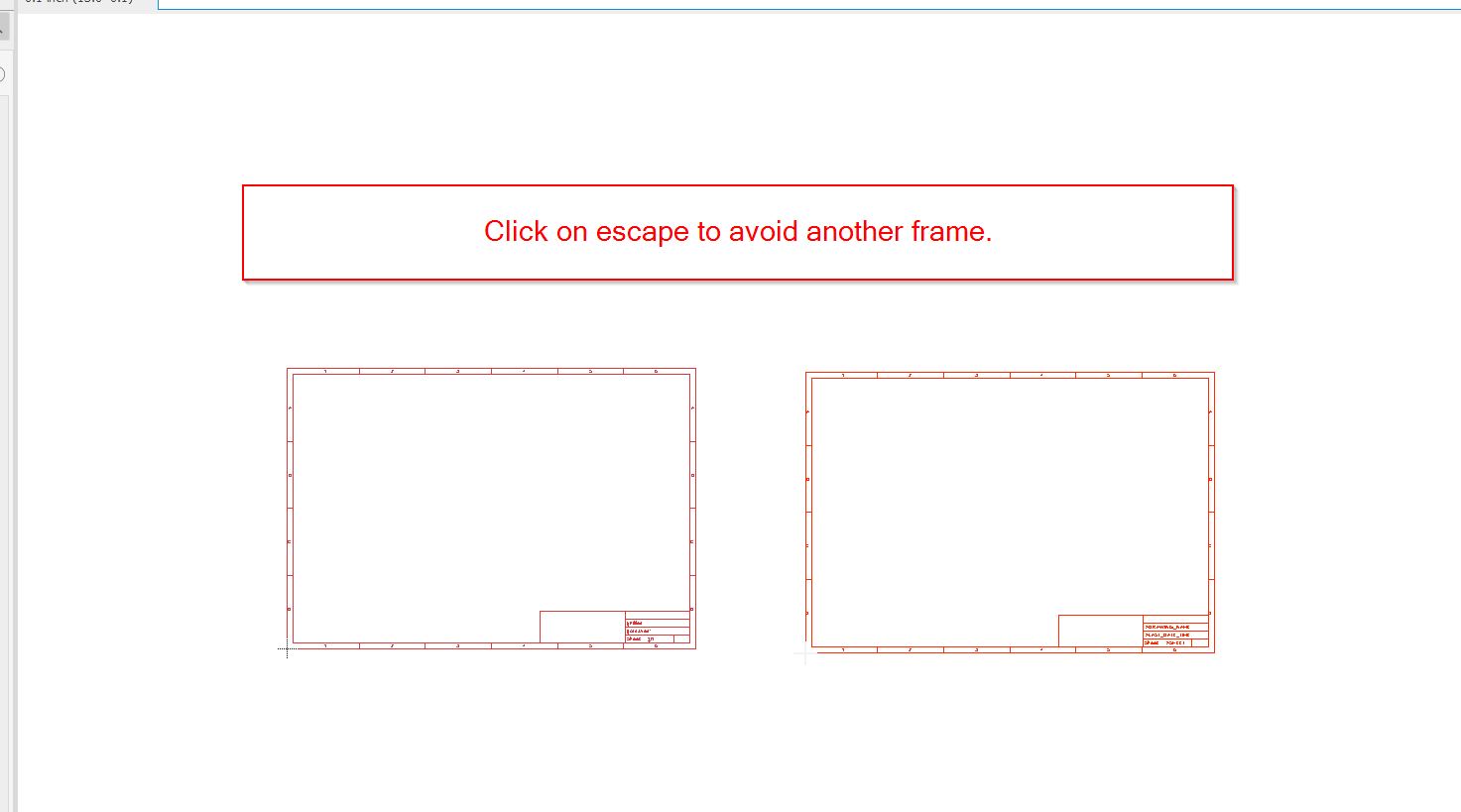
First at all, you need to get a frame to your schematic. You need to click on “add part”.
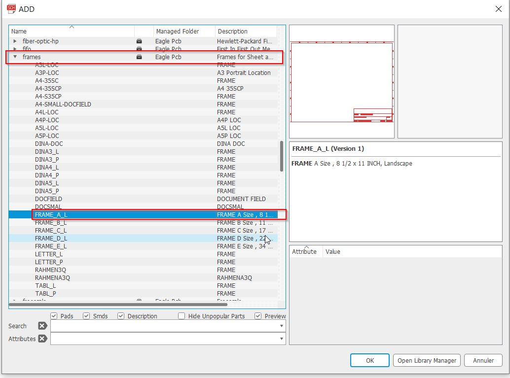
Select the frame you want:
You can easily zoom by middle mouse clicking.
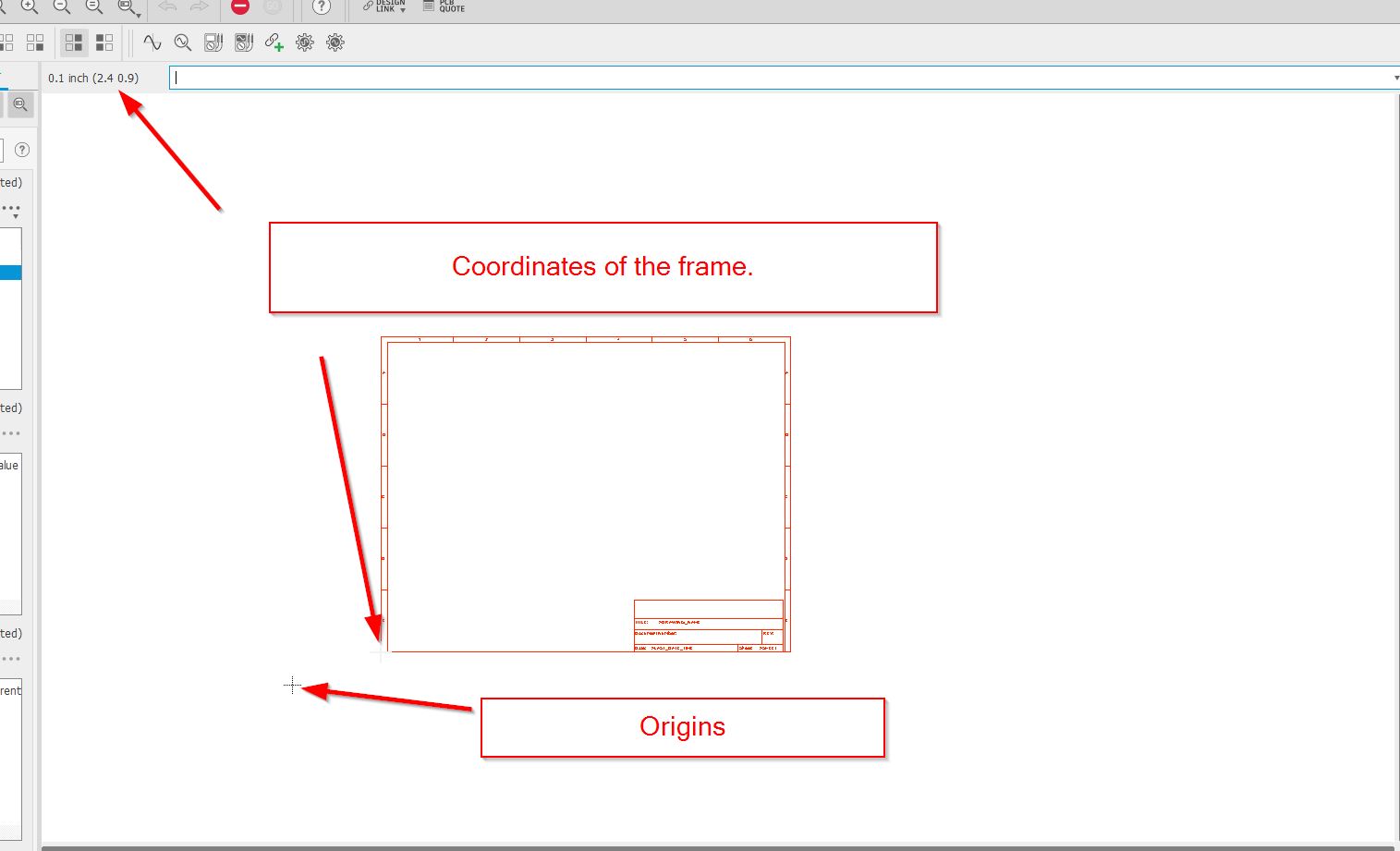
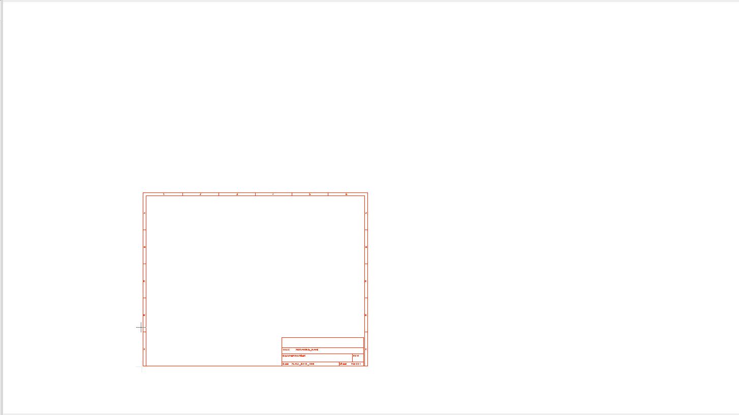 Check the origins 0.0 to install your frame. Always work on the positive side (Look at the bright side of life dixit Monty Python)
Escape.
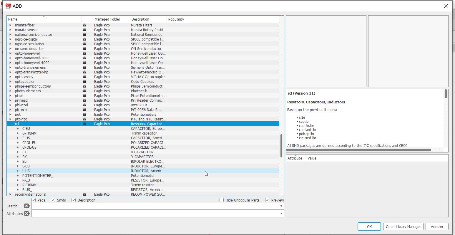
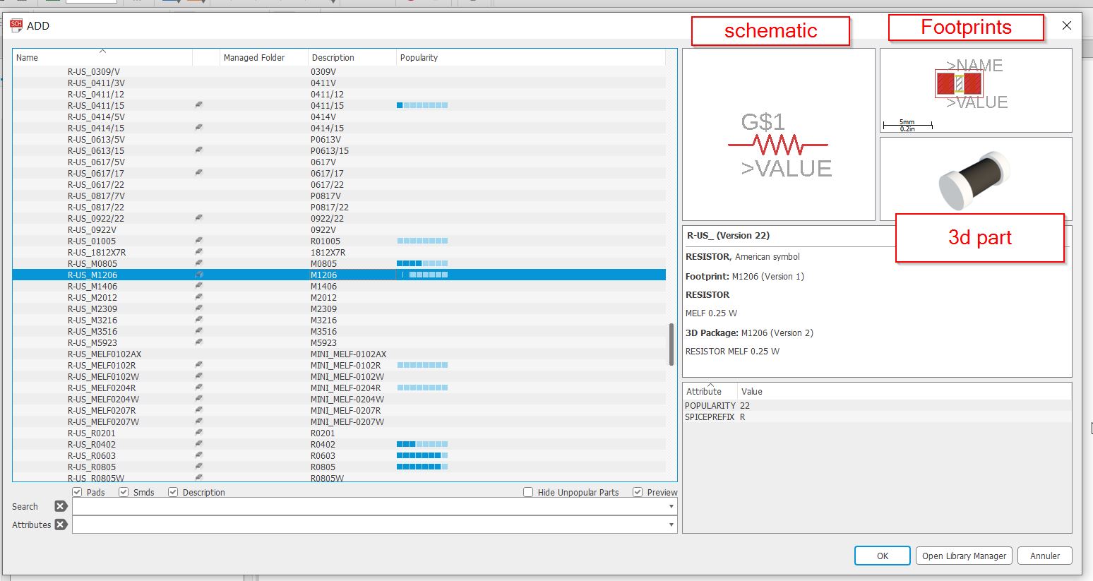
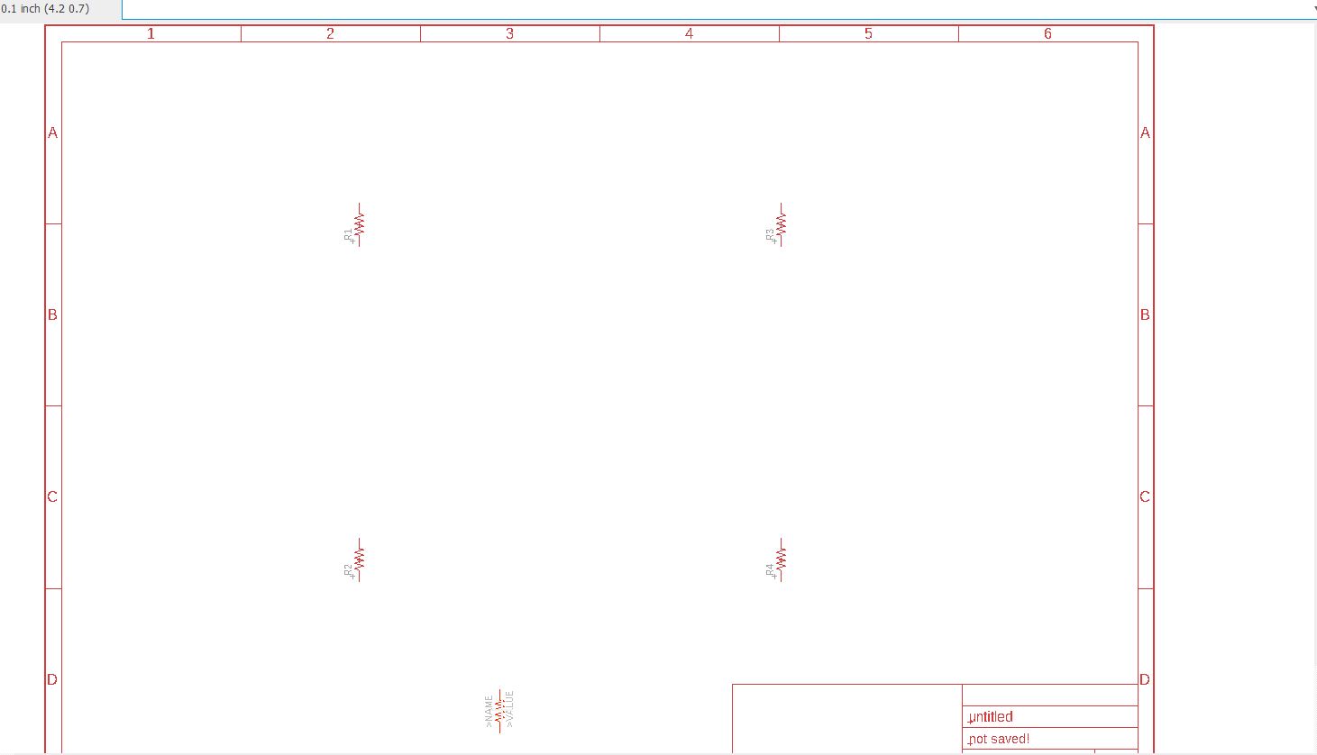
We will add some resistors, go to RCL parts.
There are american and european components.
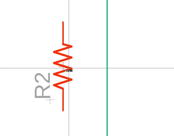
 If you right mousse button click you will get a 90° turn of your component.
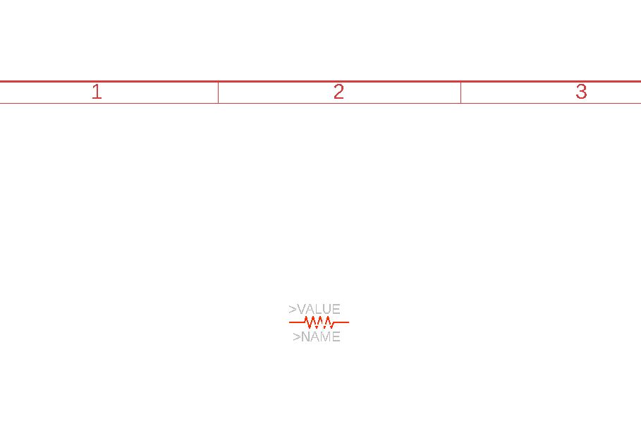
We will get 4 resistors and add timers.
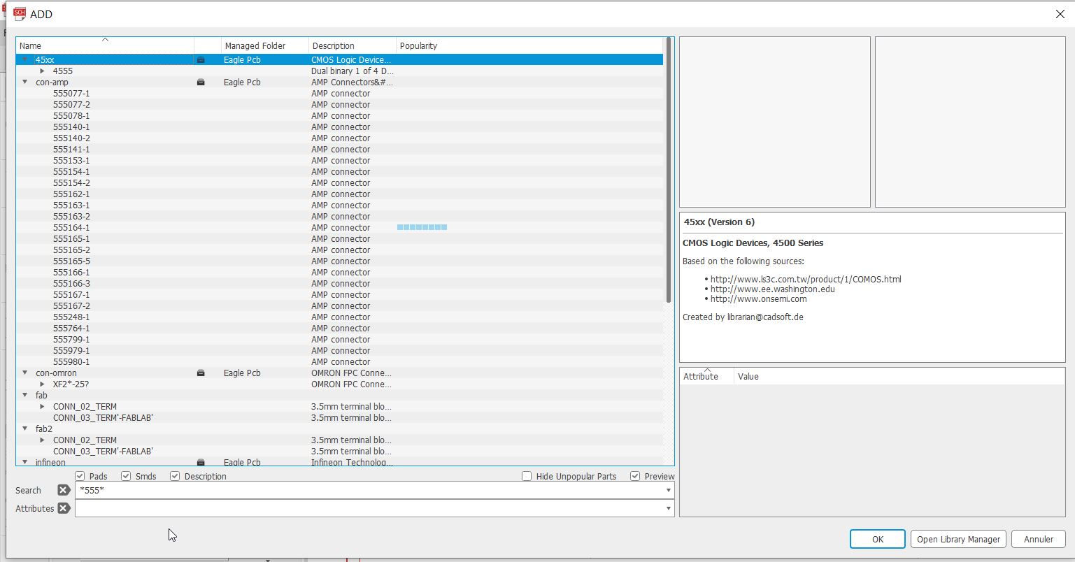
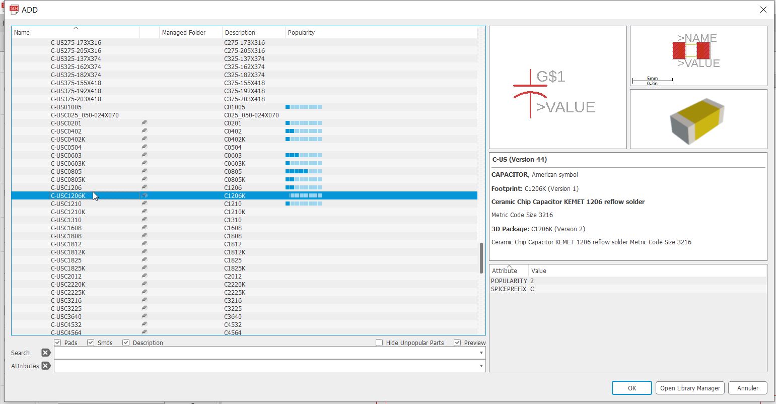
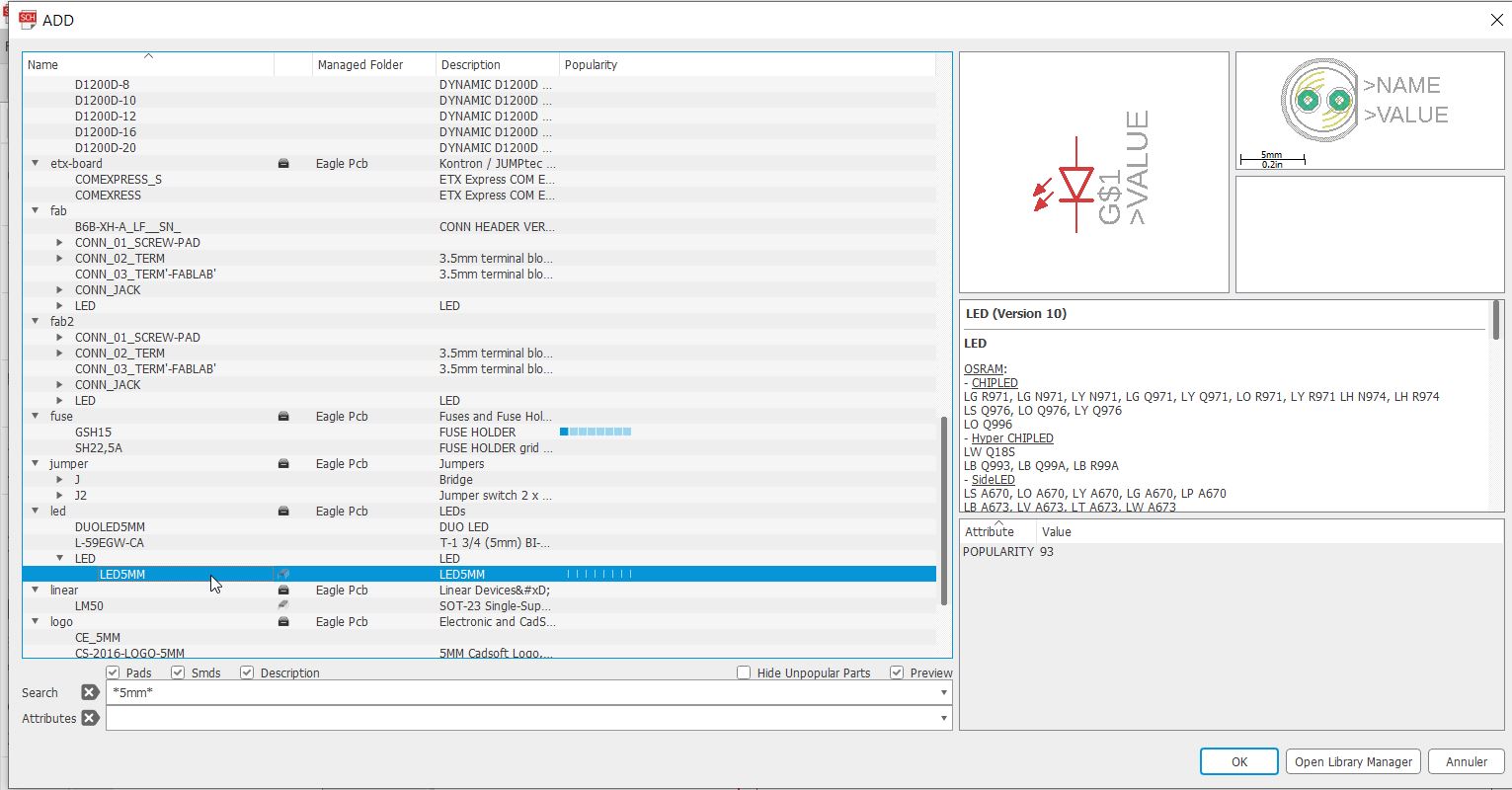
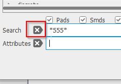
If you look for a part, and you do not have the specific name, just some letters. You have to use the * symbol for your research:
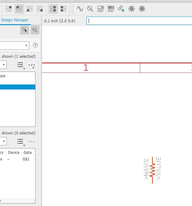
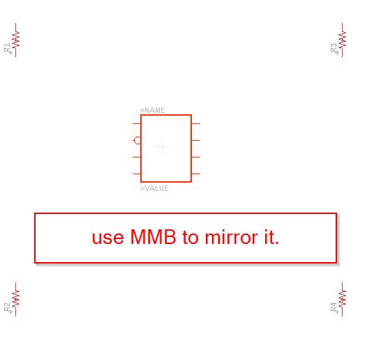
Add the timer.
 You can MMB click to mirror the part:
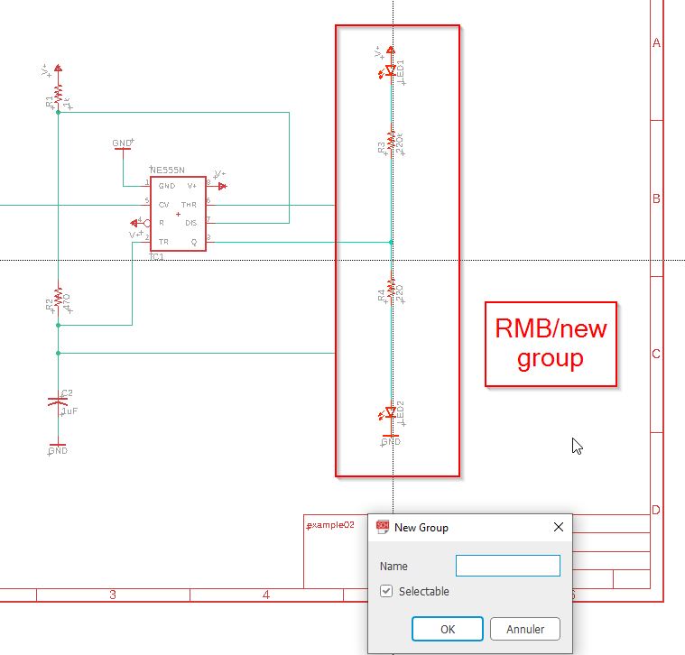
In order to move the whole parts, you select the group tool and click and drag to select all. You will have a small cross. It is important to notice that it is the all thing on this software if you have to move something!!!
We add capacitors and leds
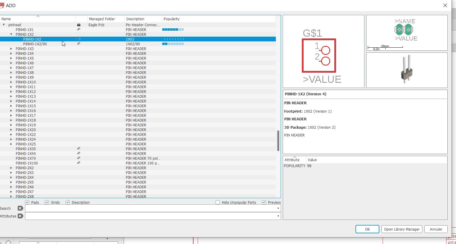
some jumpers. pinhead : PINHD-1x2
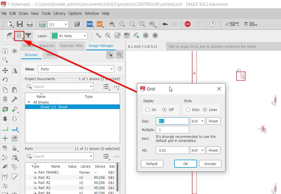
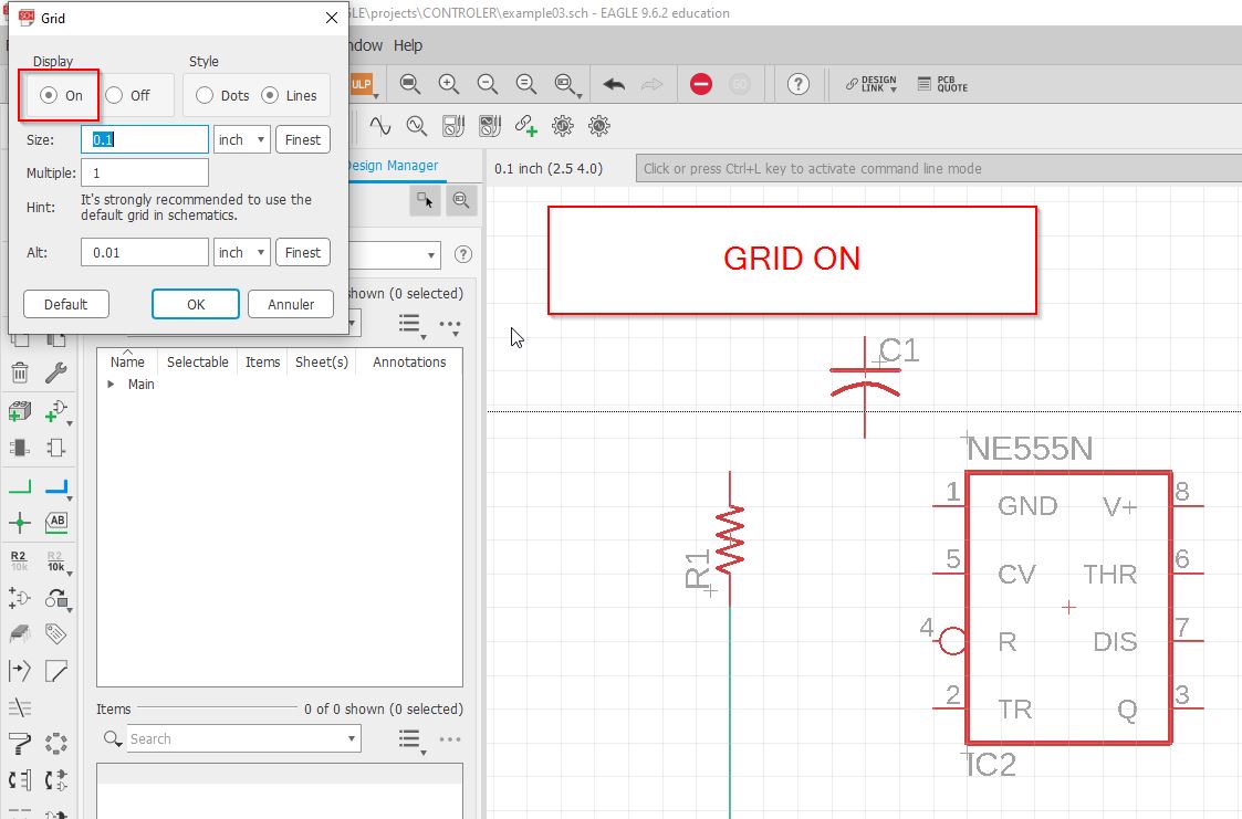
Try to get the default grid.
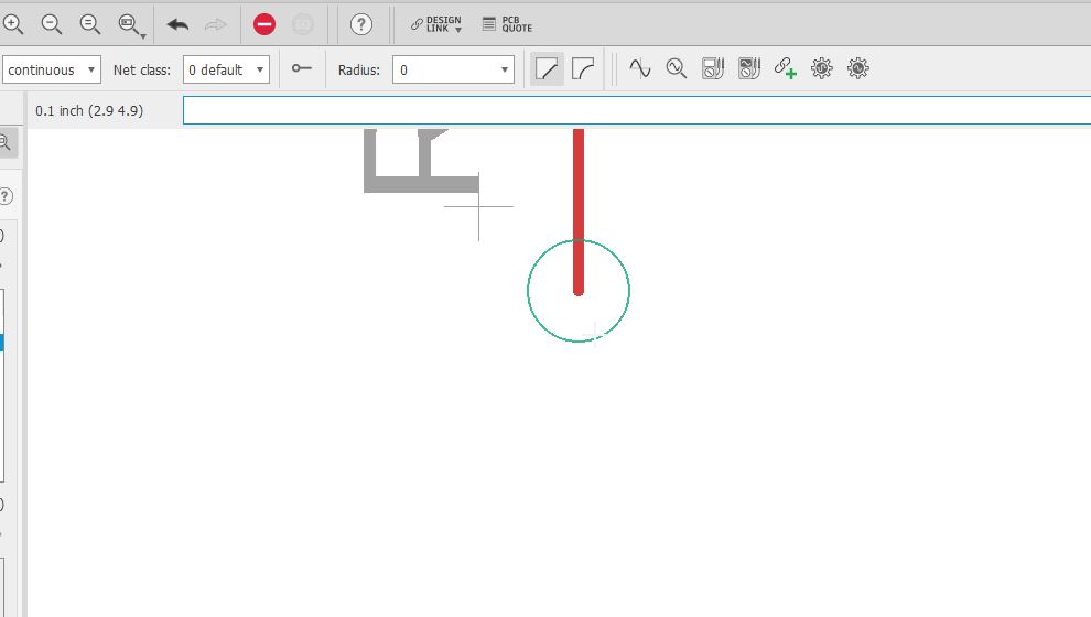
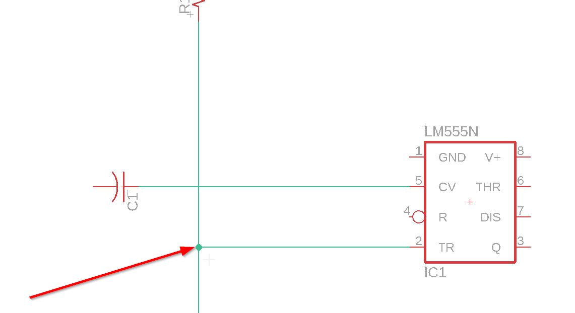
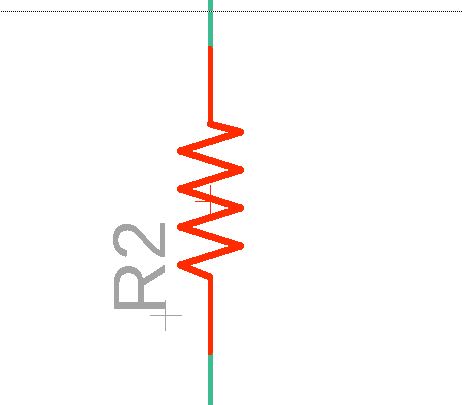
There is a circle around the end of the part, to notice you that you are at the endpoint.
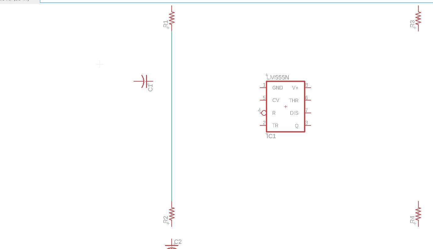
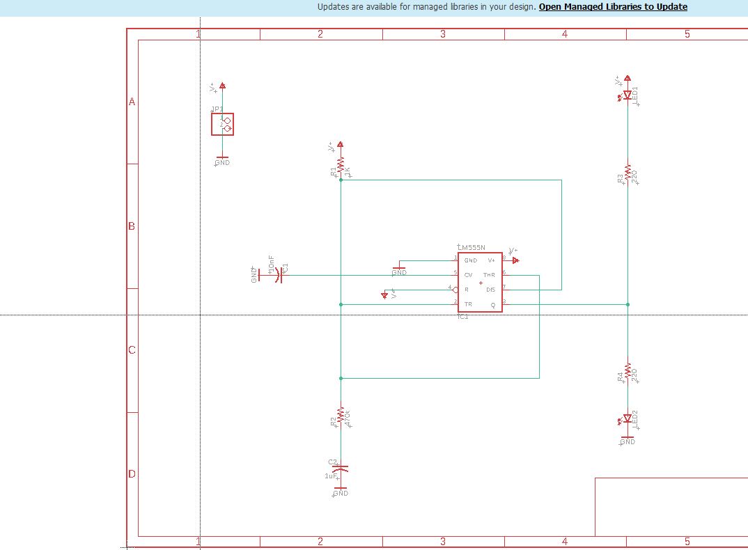
If you connect a net to another net you will see the junction:
C:\github\2023\fabien-jonckheere\docs\images\eagle\junction.jpg
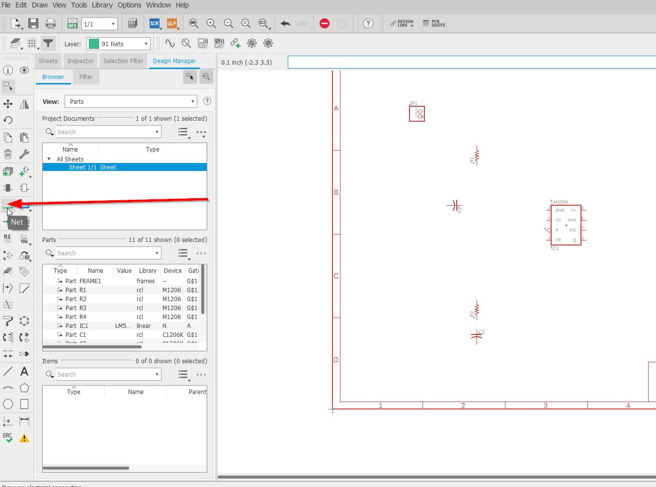
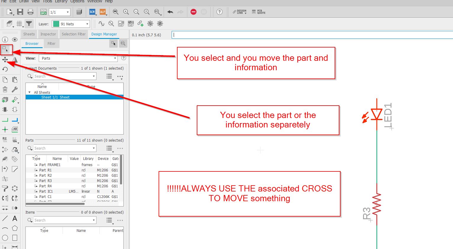
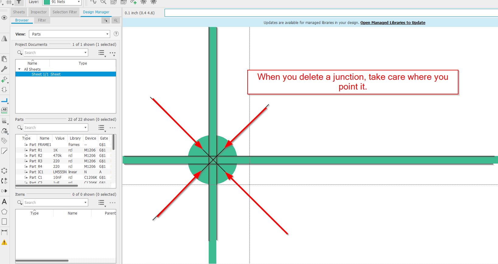
/////Warning, to move separetely items or components, it is important to use precise tools:
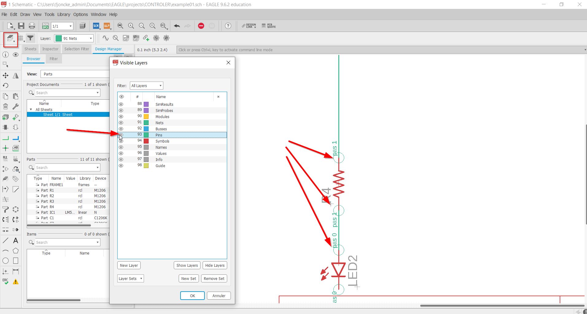
If you have some difficulties to see the endpoints of your components, use the pins layer.
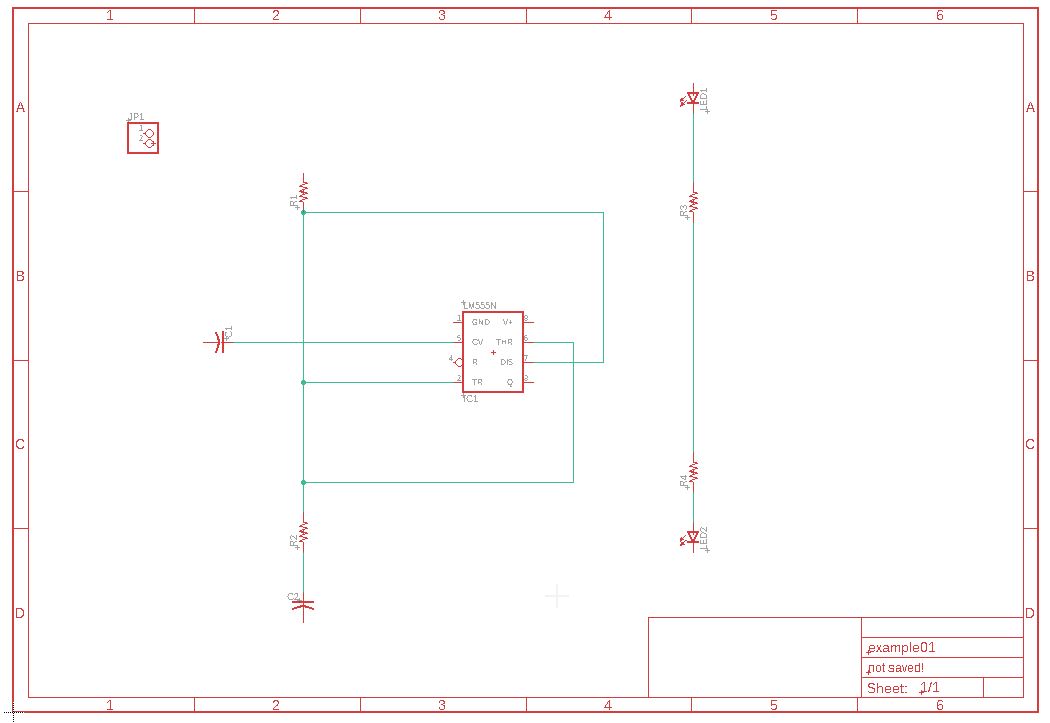
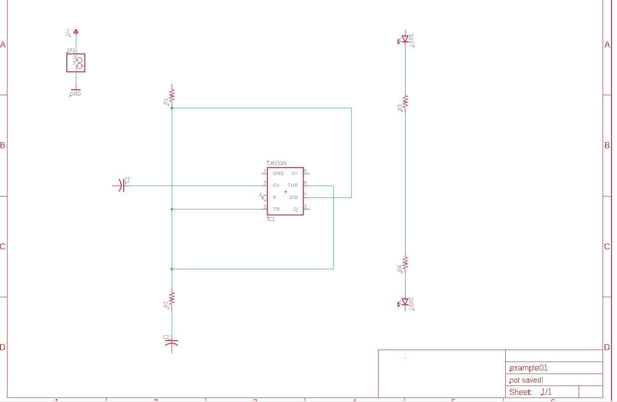
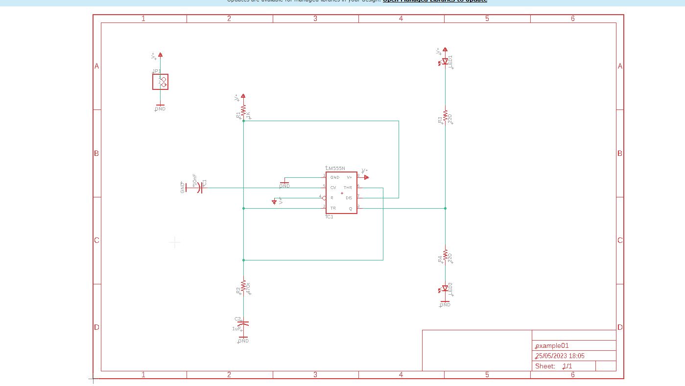
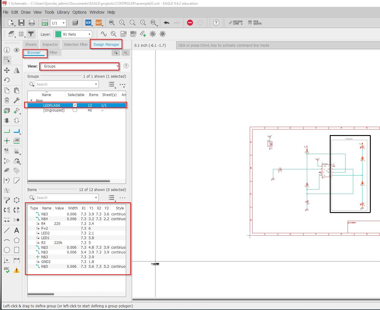
this is an overview of the schematics
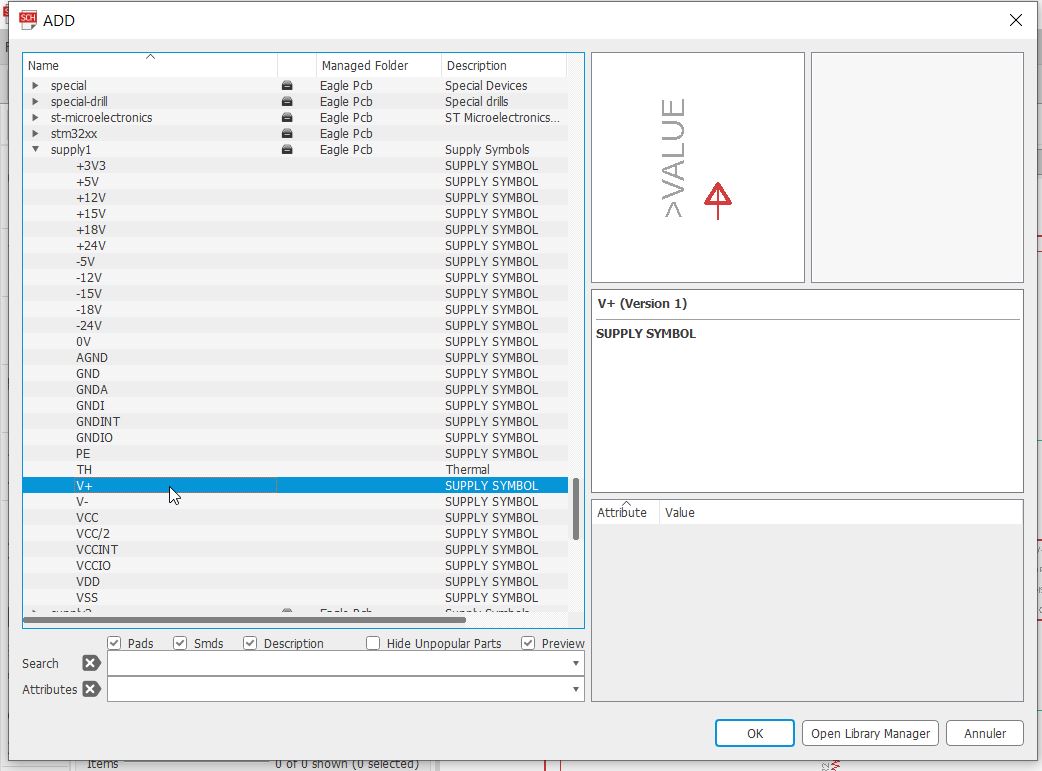
We will add the V+ supply and…
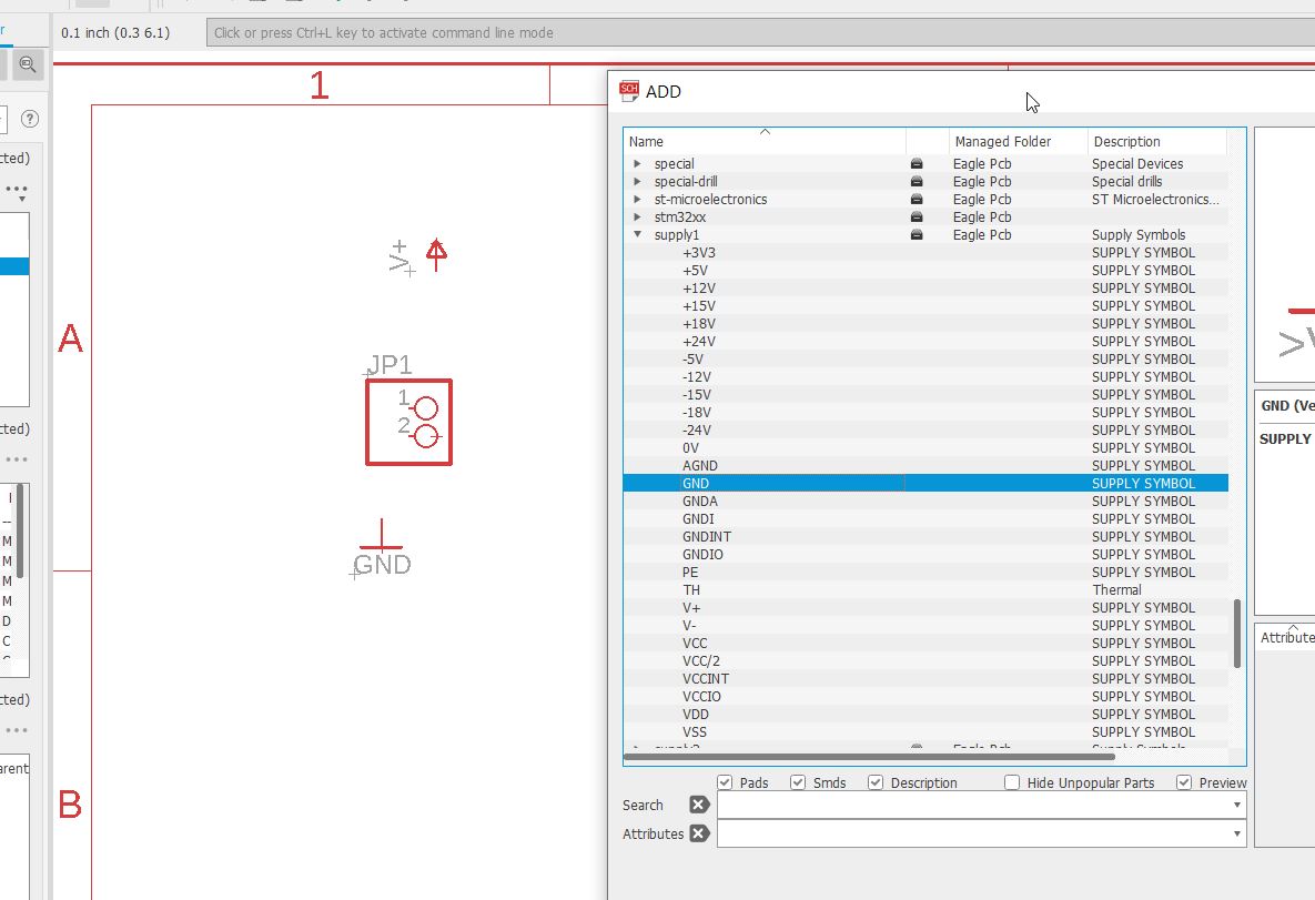
… the ground.
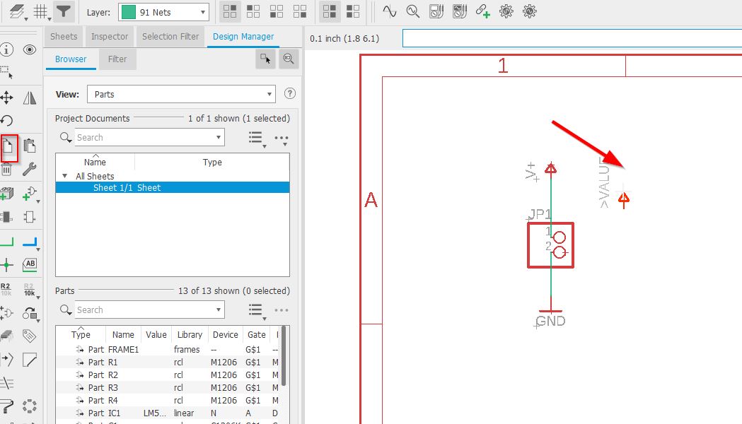
We got that
To copy, you can use the perfect tool.
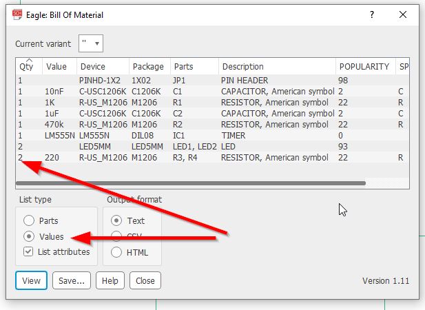
With the BOM option, you can generate a bill of material.
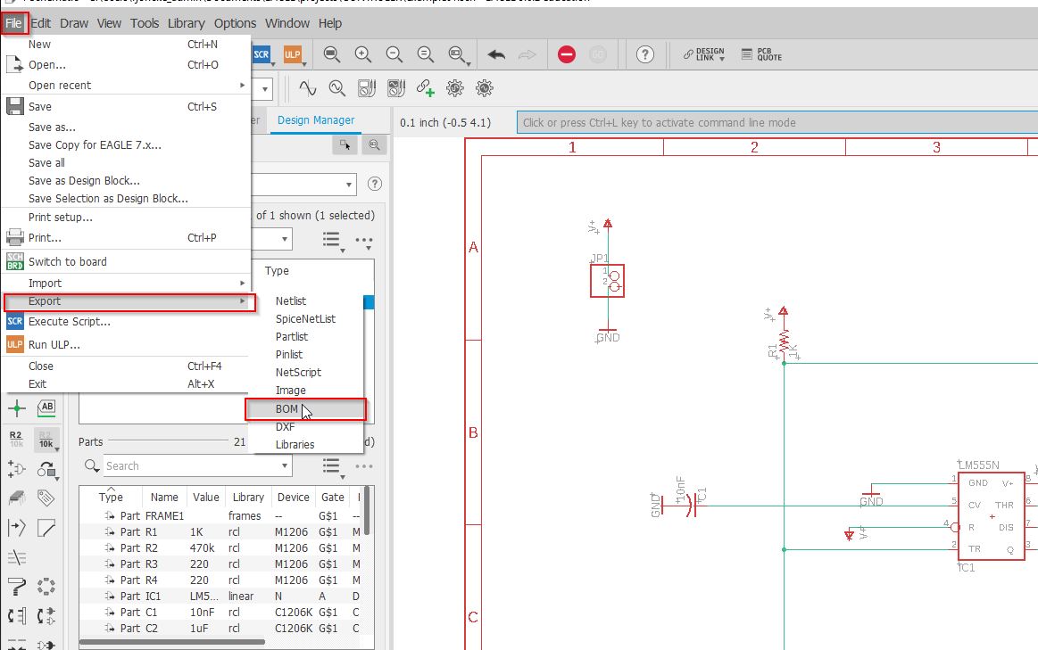
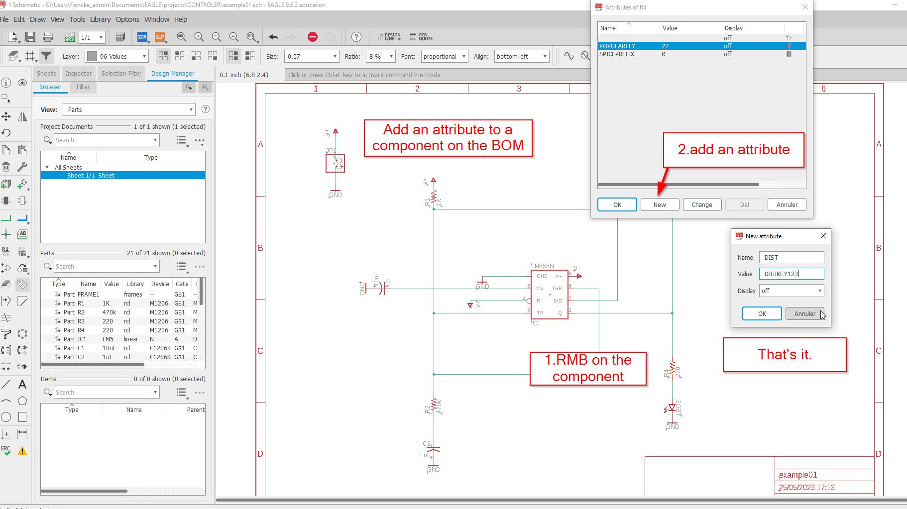
To add specificiations called attribute on the BOM, you right click button on the component, and you will add for example distributor.
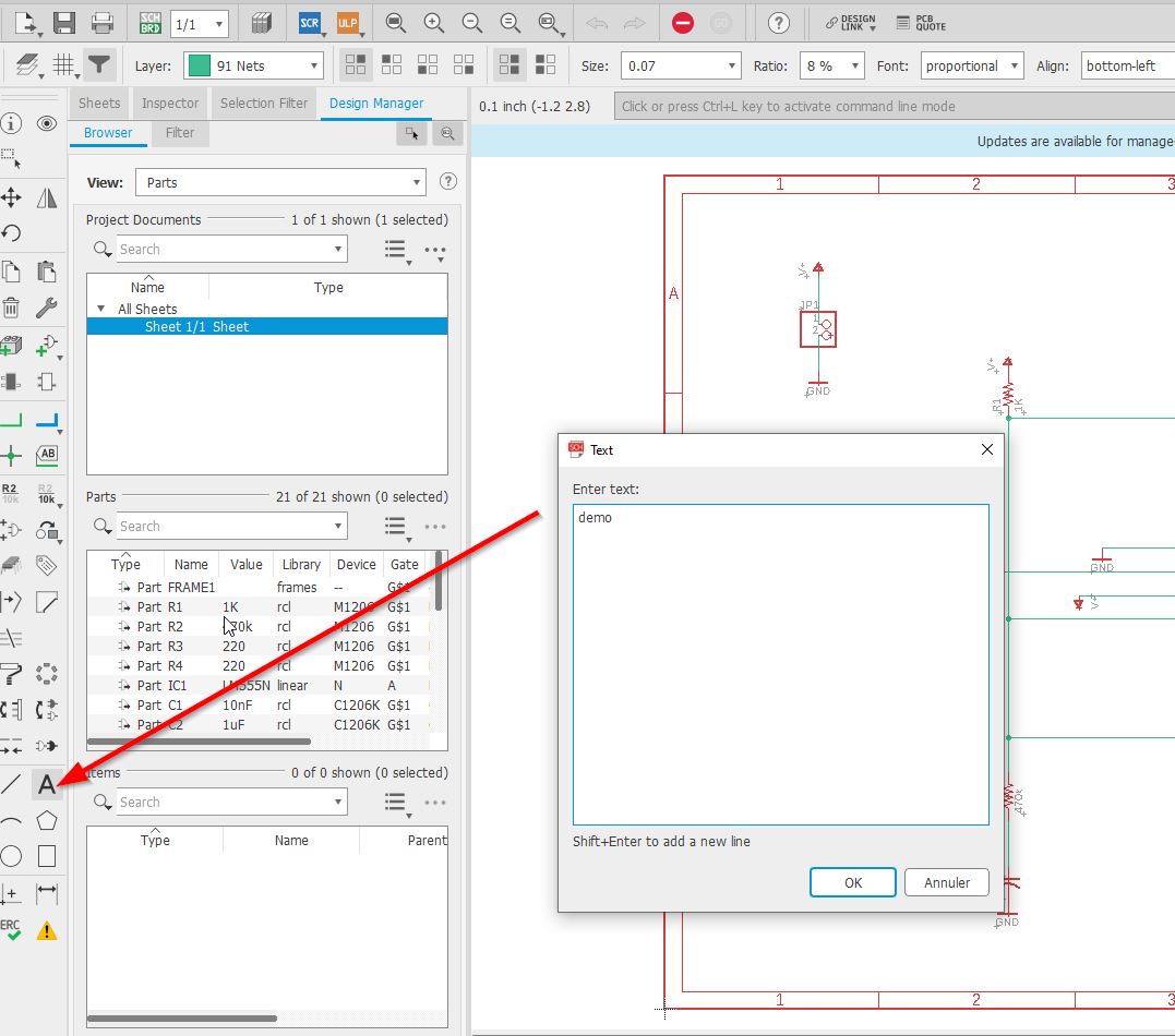
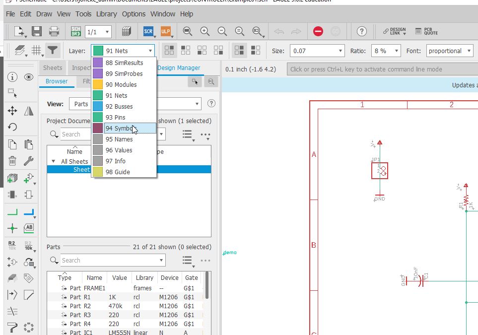
For the text editor, you have to check where you want to have your text out. In my cas, I would like get this out of the net layer.
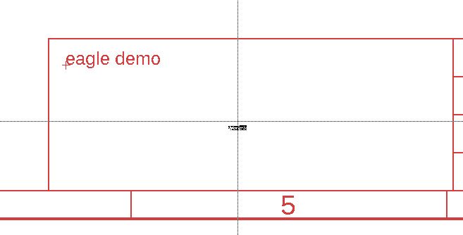
The grid is activated, and the text is moving from 0.1 to 0.1. To avoid that and get a smooth move, You pres ALT key.
If you need to add a junction to cross-over nets, you can use the
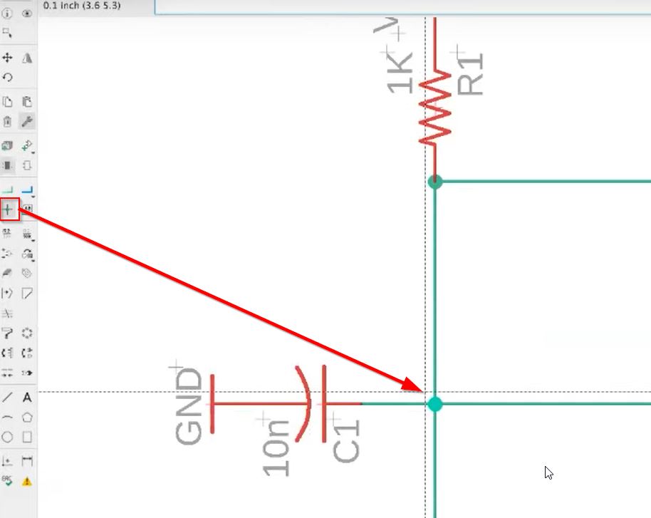
To get a more precised cursor, you can find a full horizontal and vertical one.
Converting your board into a schematic:
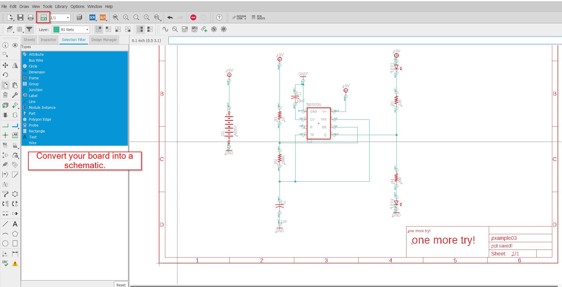
If the board file is not created, it will invite you to generate it:
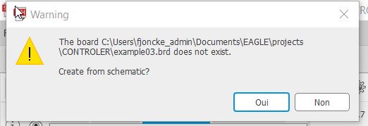
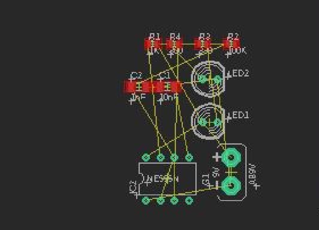
You will get the components in a black background:
EAGLE TO FUSION 360
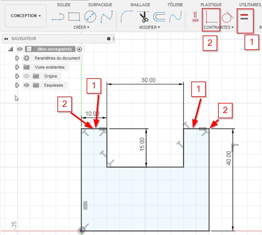
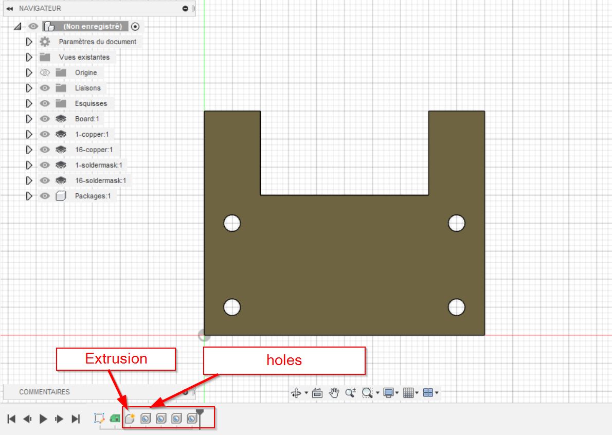
Create a new folder ( Eagle Example) and use the sketch command, select the front view. You can start to make your outer edges of the board.
Use the line tool to create a shape, click on the origin to next point and you come back to the beginning. You will see that the created shape will be highlighted.
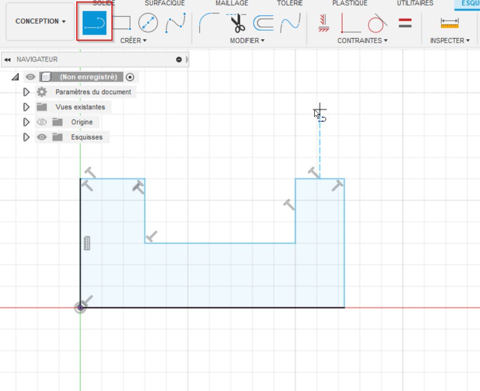
To be straight, the constraints command [1] will make equal lines and the [2] tool will get vertical or horizontal ones. For this tool, if you need to have a point at the same level of a line, use the [2] tool by clicking the line and the point.
I have added holes to maintain the board.
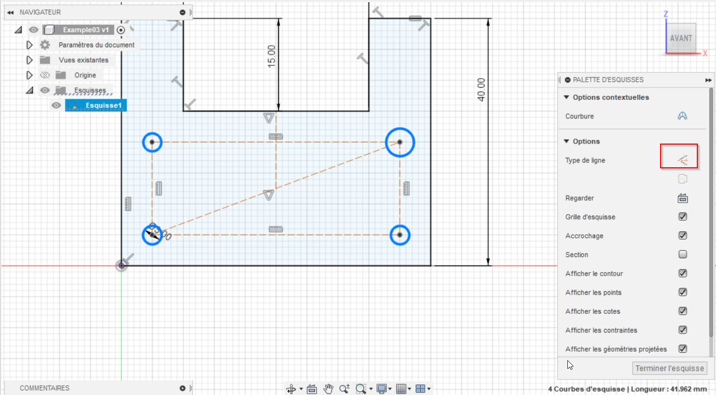
The shortcut [D] provides dimensions, you can find it at the “create folder” When it is dark, the sketch has all required dimensions, you can use the “create PCB” function. Use the independant option.
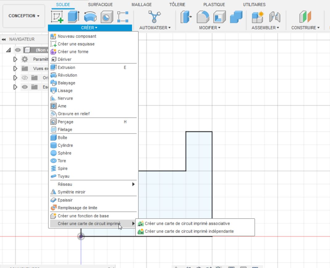
Select the profil and the origin of your PCB. You can easily change the options: point, directions.
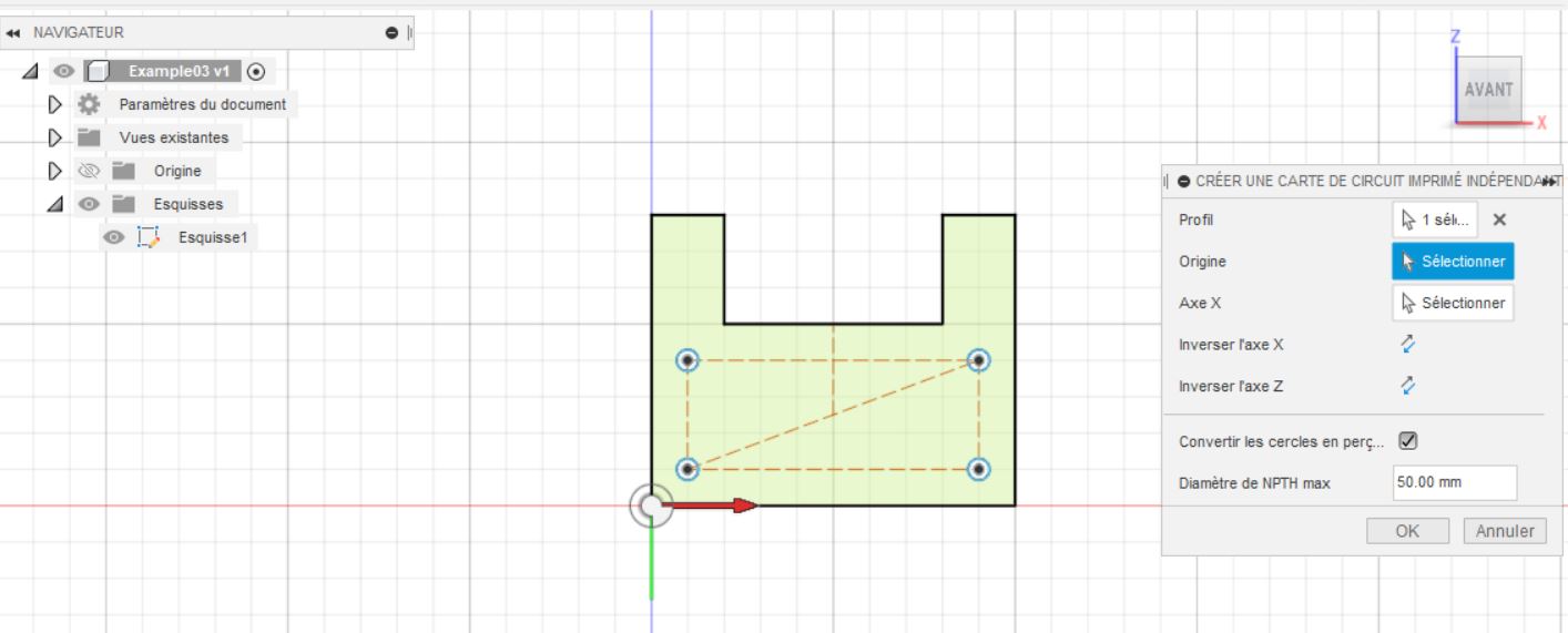
The extrusion and holes are directly converted to PCB functions.
Get back on EAGLE:
Click on the fusion 360 tab, and link to an existing fusion 360 design.
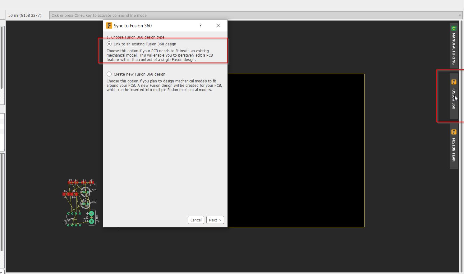
Follow the options:

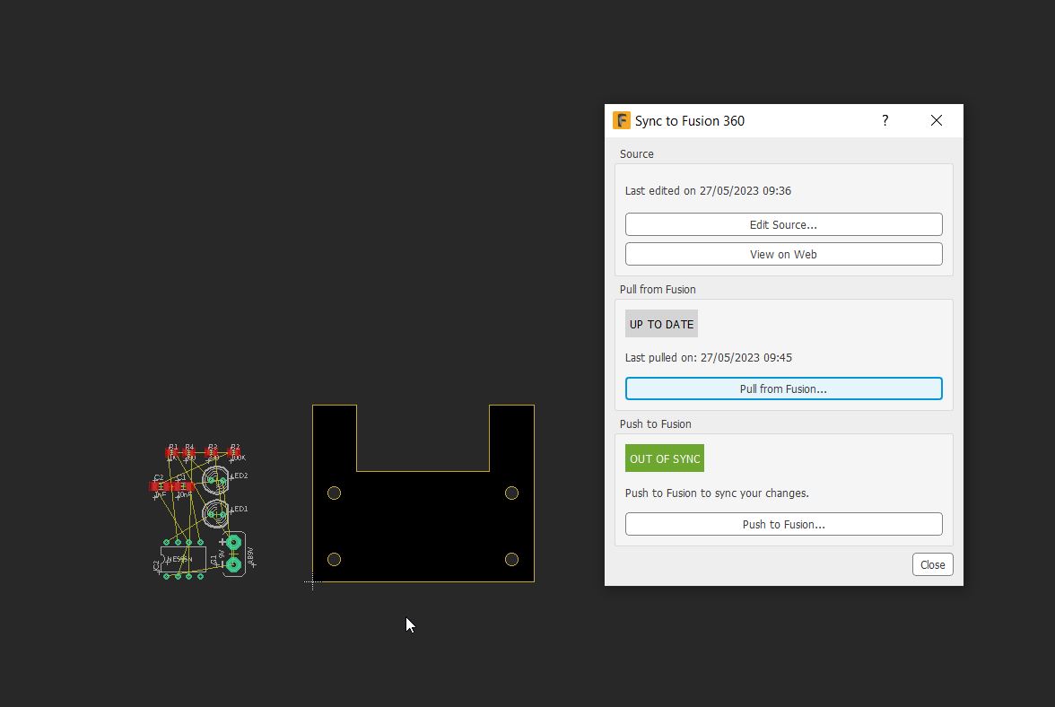
And finally PULL FROM FUSION:
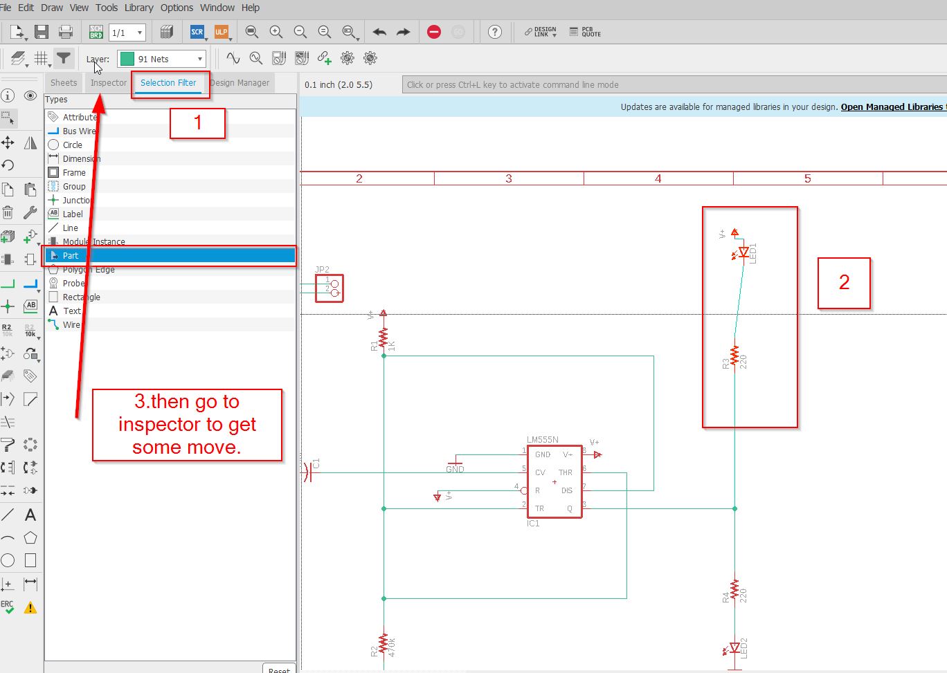
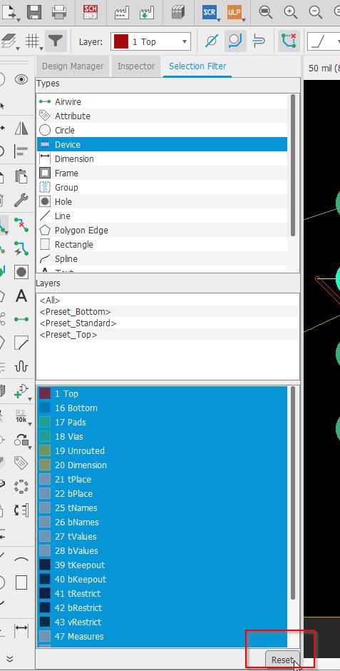
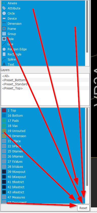
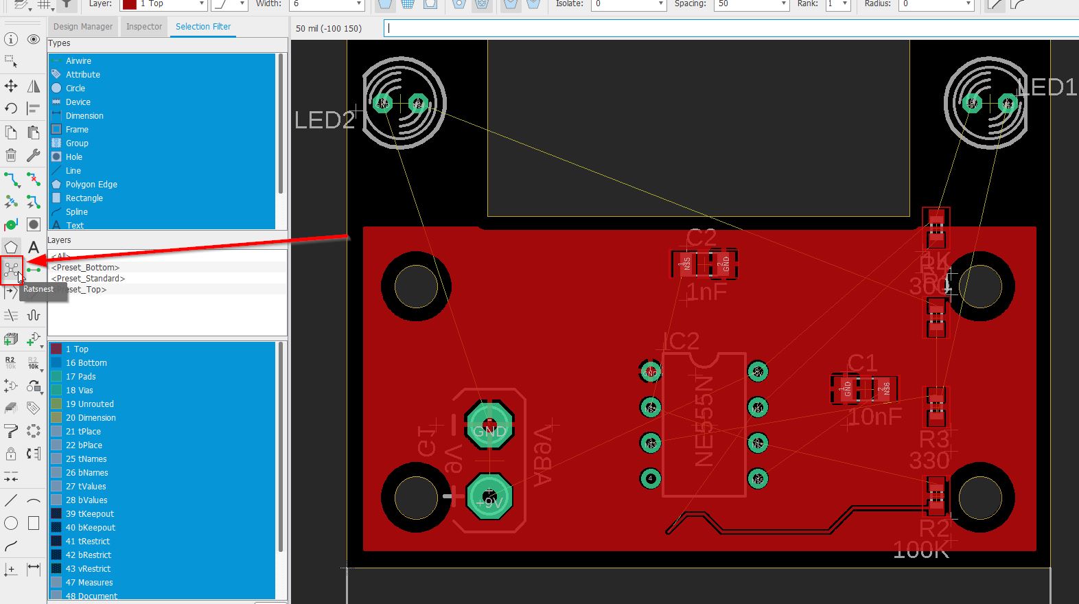
As a beginner, it could be quickly the mess to move items, use the selection filter to get only your devices:
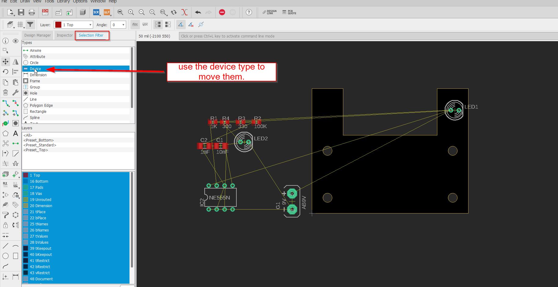
/////// WARNING/////////
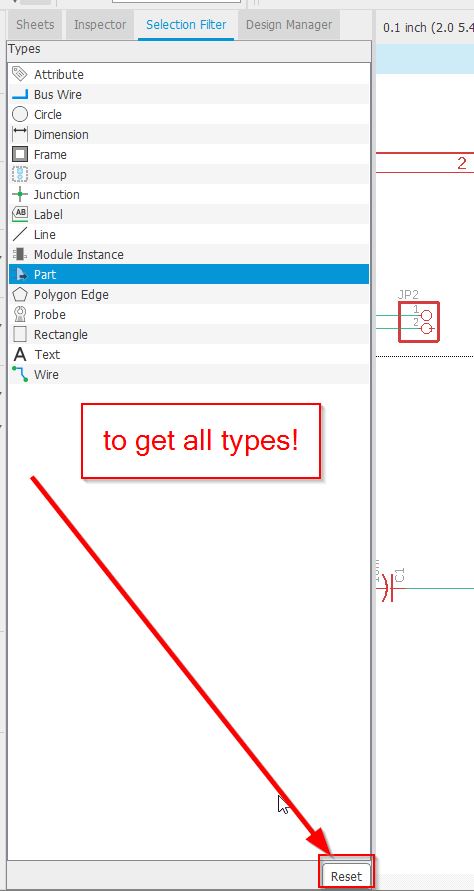
It is good to know that if you want to cancel a selection for anything ( components research or this selection filter) you need to click on reset!!!!
Eagle has some tricky operations, and sometimes it makes me crazy. That’s why I write everthing I found down.
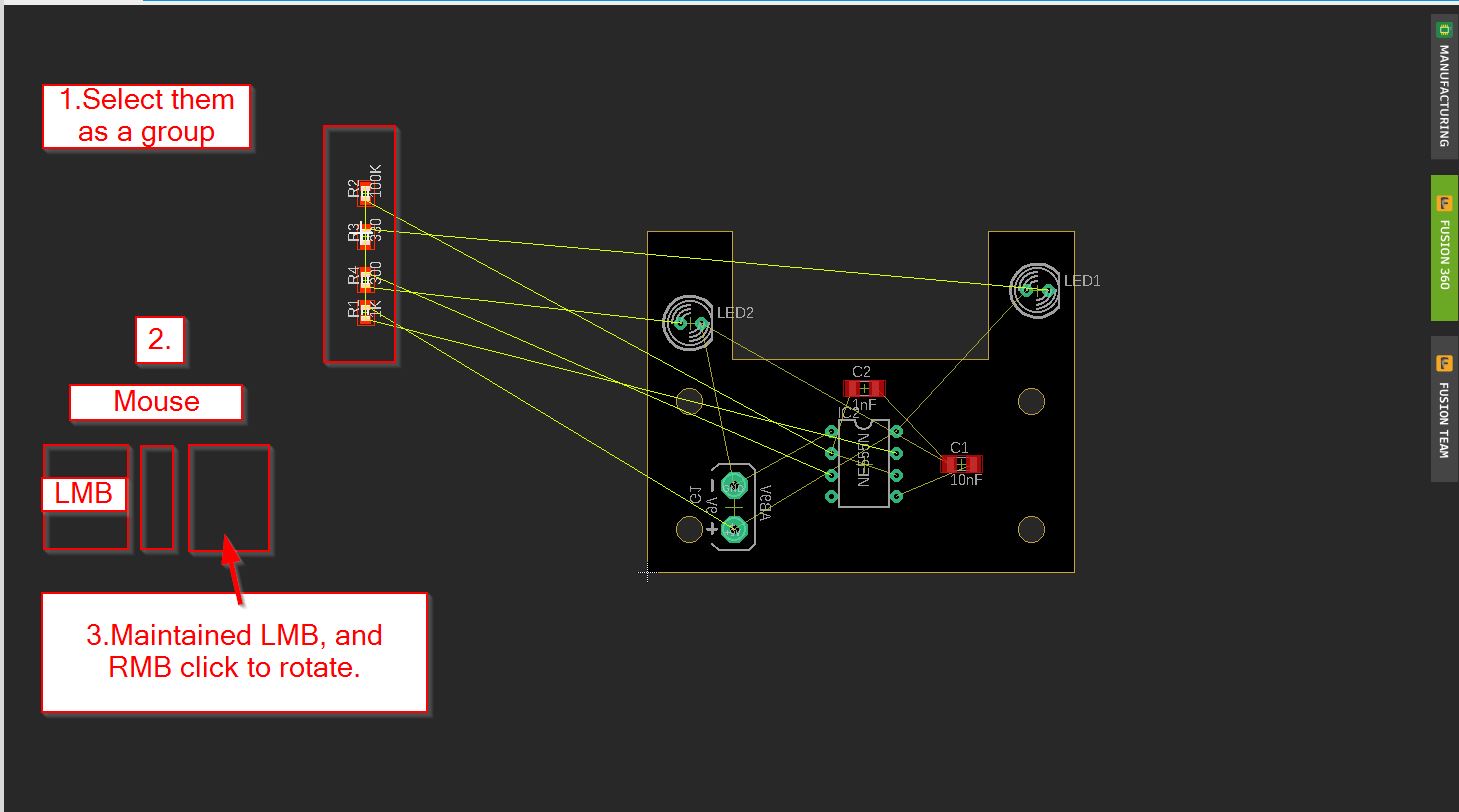
To rotate a group, you do not only select and rotate (which is common on 2D softwares such as inkscape)
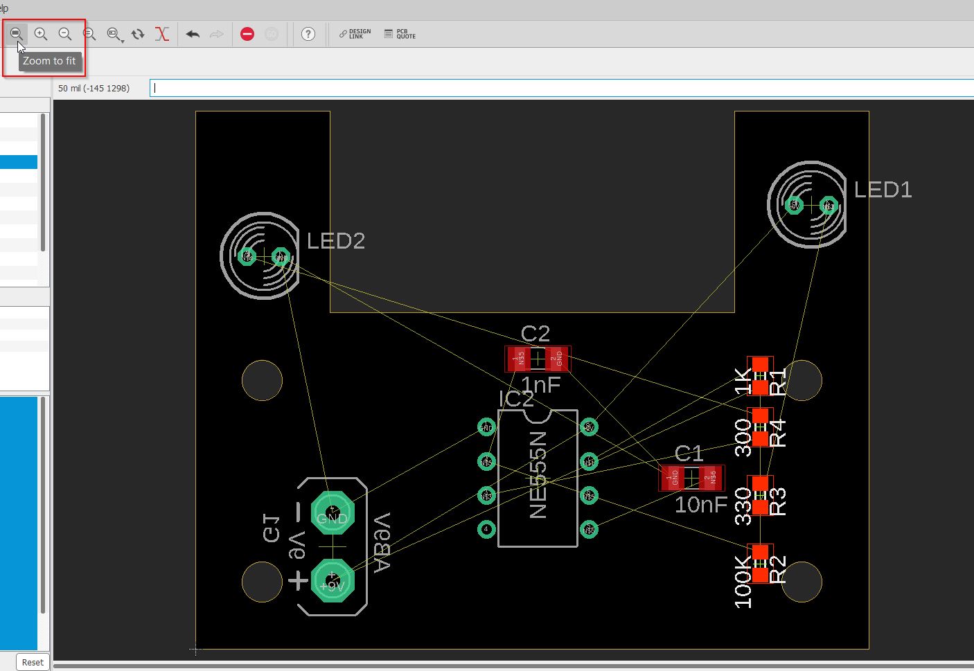
When you are far for the design, use the zoomtofit function.
After a while, you have moved components, and the net can be regenerated by using the rastnet process:
When you 2d draw, it is always beautiful to have same spaces between components. You need to know about the alignment functions.
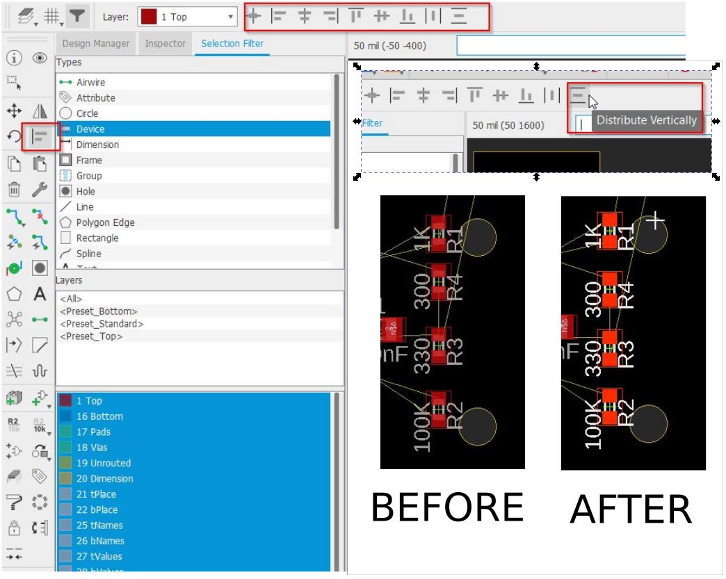
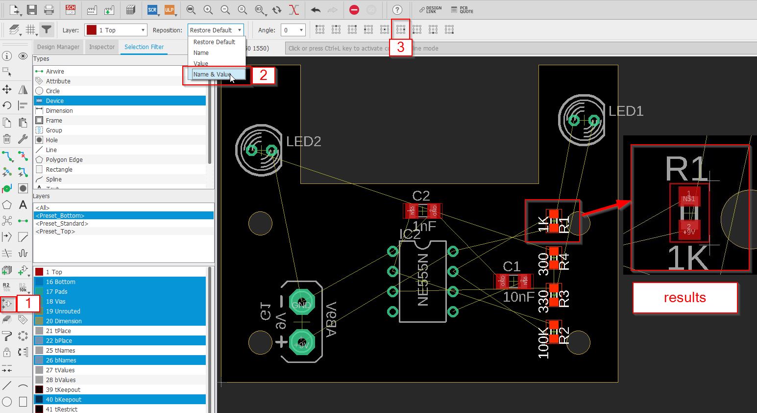
You better get organized for the attributes as well. They are informations related to the components. When you rotate components, they follow the move. So you can reorganize them as well.
I do not really like the dimensions functions of EAGLE, better to be straight on Fusion and then you get back to Eagle. But It is possible to add measurements.
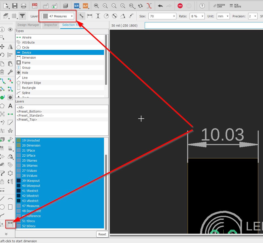
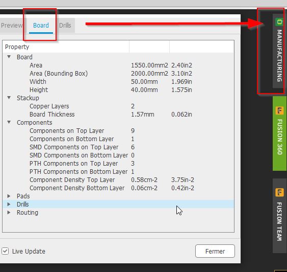
Dimensions and informations can be found on the manufacturer tab.
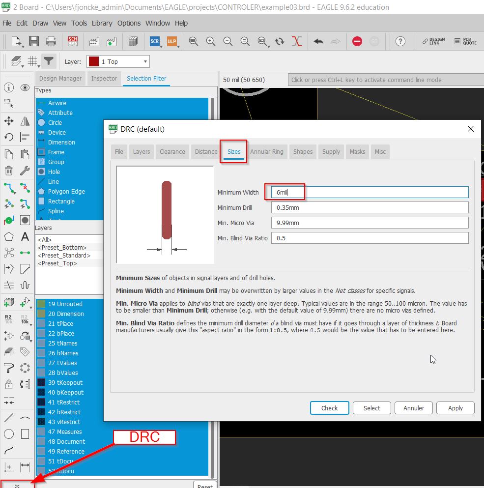
You can start to wire your board circuit, but first look at the thickness of your presets. Here I will change 6 to 12mil. You have to check the design rules check function. You define all your presets for your drawing here.
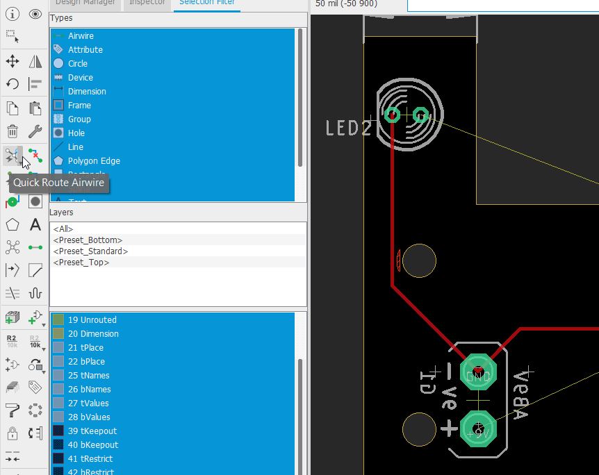
When you have simple paths to make, you can use the quick route airwire tool. Here I have clicked on the LED and the - of 9V. The path comes instantanetely.
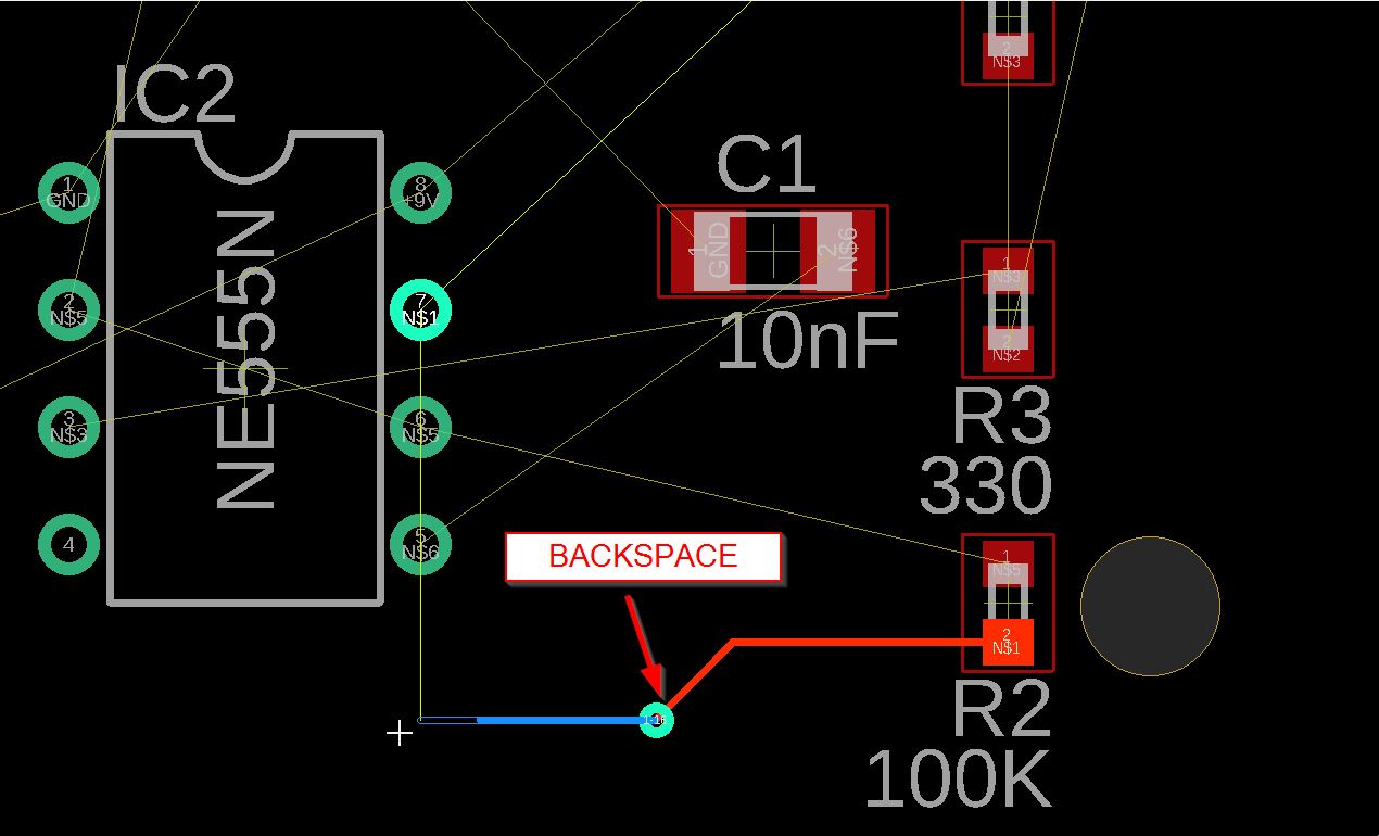
/////////// SHORTCUTS:
[backspace] to cancel a route and get back to the previous route. [SPACE BAR] to add a VIA to the end of your route.
When you use this option, the via will guide you from the top layer to the bottom one. The wire will be blue.
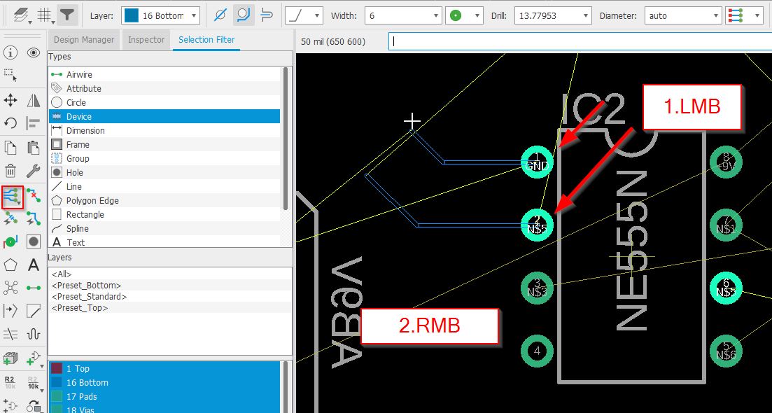
It is possible to have a route multiple airwire. You LMB on the pins you want and then RMB and start your route.
You have different options, you can easily get them by writing “assign” in the command line editor: minspacing - Alt+D incspacing - Alt+S decspacing - ALT+A
(see the informations at the bottom part)
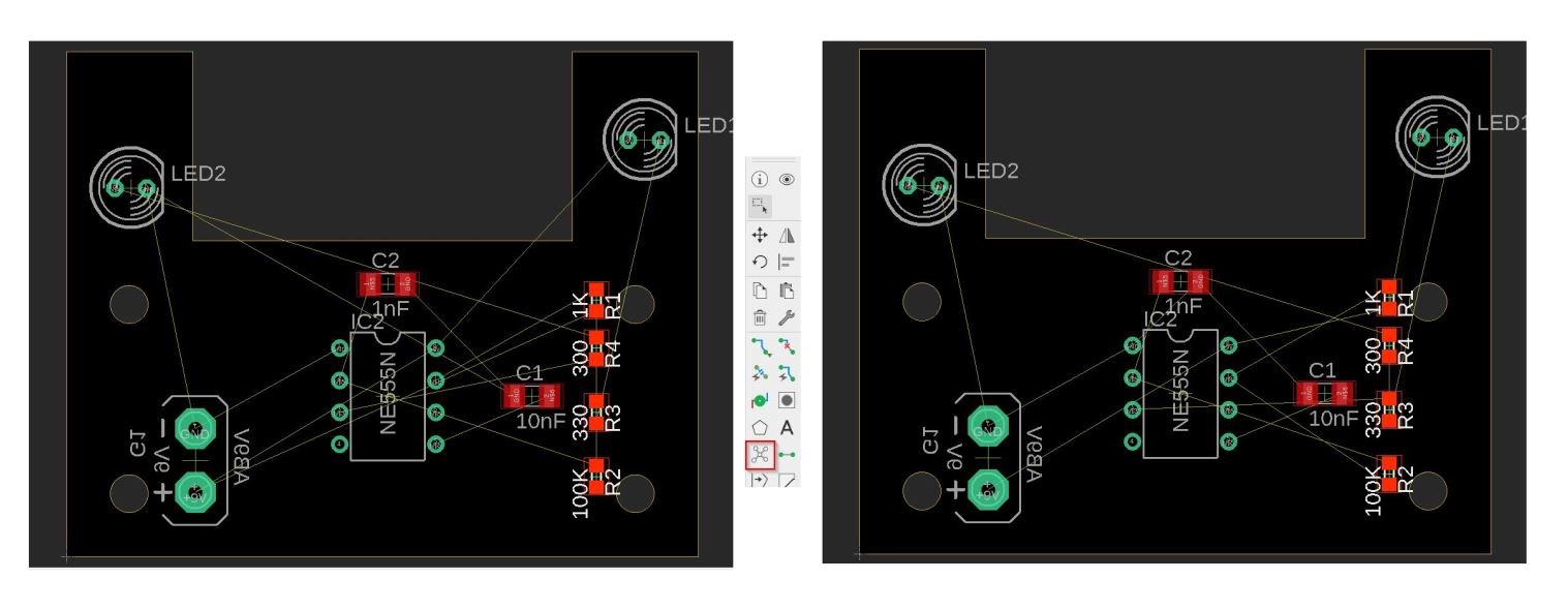
rip up function
This function has several options. The default one remove segment.
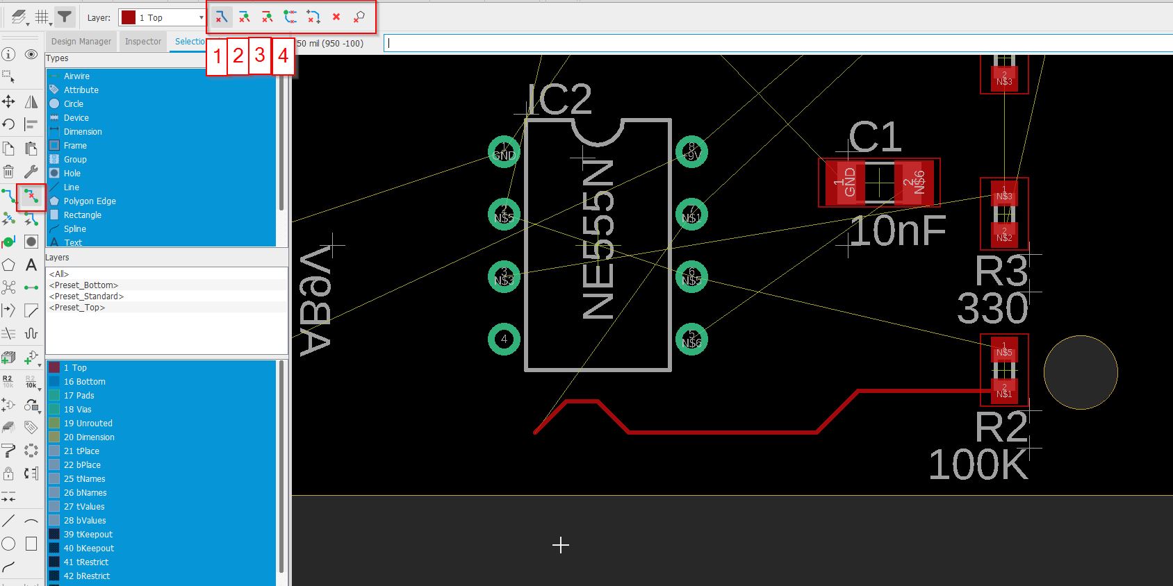
1 just a segment 2 connected copper - delete till the component - top or bottom layer, everything is gone 3 connected copper on same layer 4 signal (not try)
The 5th( which is not marked) is convenient because it rip the wire between two components up. The 6th will remove all wires!! Be carefull!!
/// I was a bit frustrated because the command was not working!! But It rings a bell and thought: you forgot something. I went deeply to what it is annoying on EAGLE. And I remenber… THE SELECTION FILTER!!! I use the reset function to get all default selection.
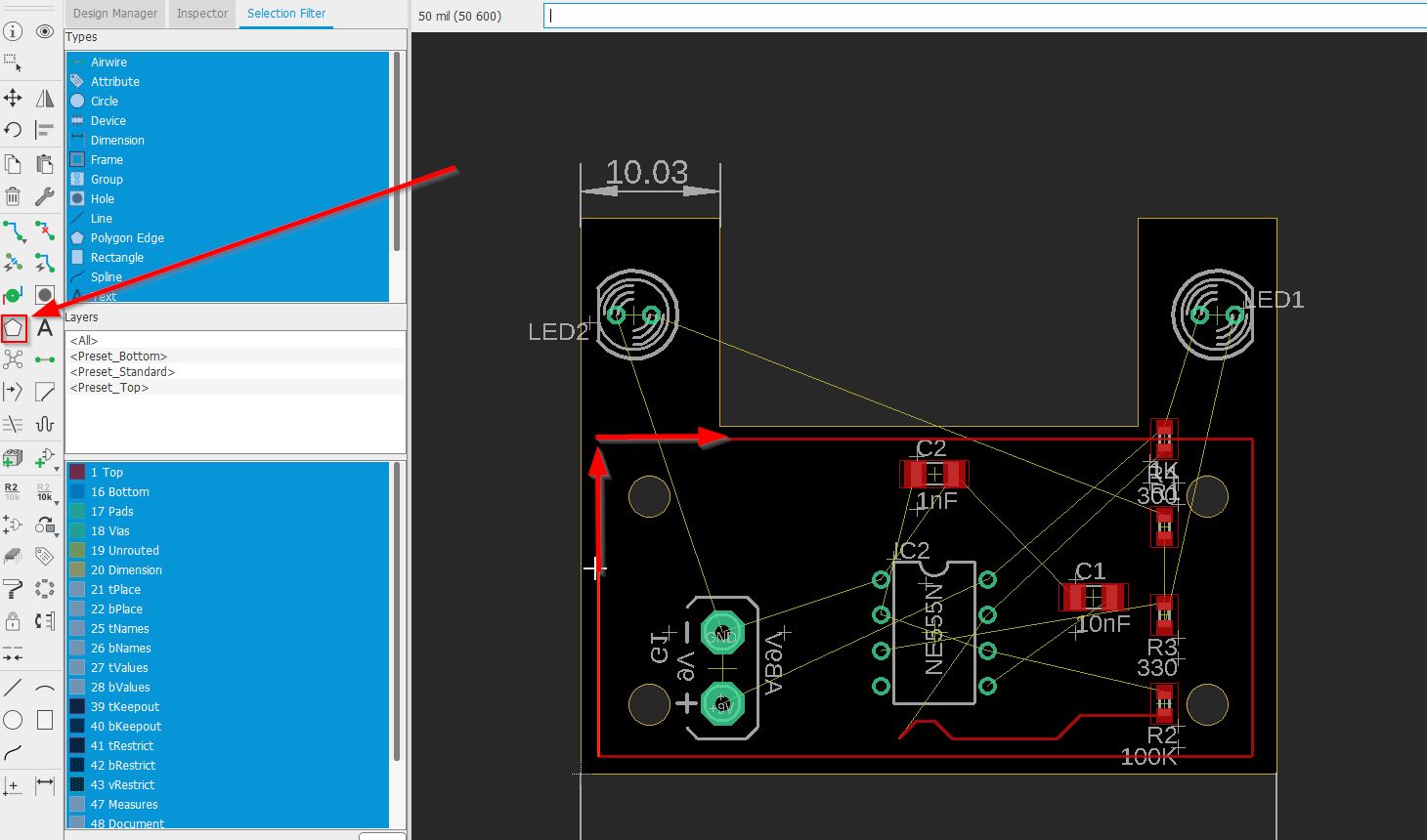
Create a polygon:
You can easily create different shapes by using the polygon tool.
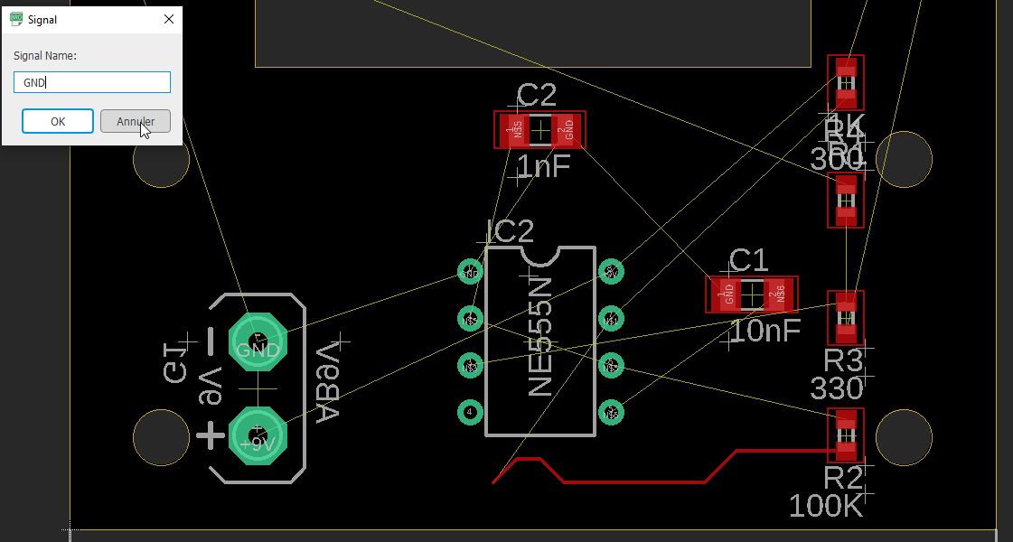 You assign GND to this.
Rastnest will fill the entire shape in. It will create the shape for holes and pins.
How to remove the polygon?
87-ripuppolygon
If you need to remove it, use the ripup command and select the right option.
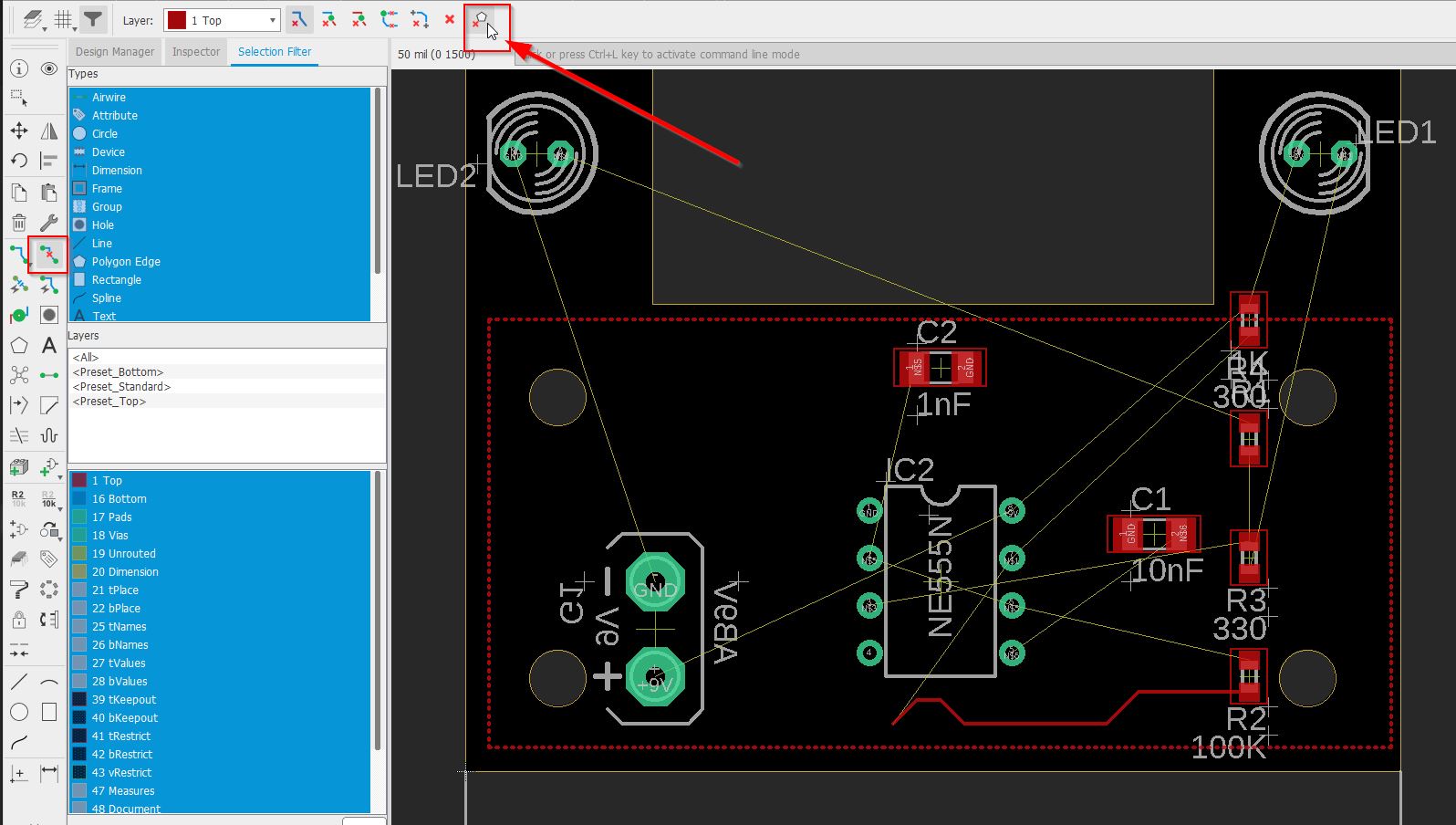
my board will be a polygon!
It is easy to get the board as a polygon. You RMB an edge of the board, and convert to a polygon by copy the shape.
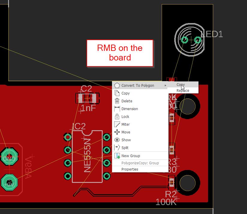
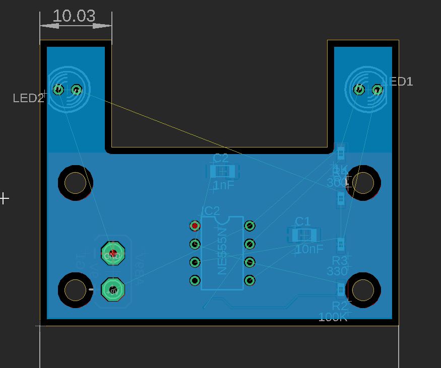
IT will ask you where to copy it, you select the bottom layer. Then you can rastnest, and find the perfect polygon
How to change a component?
By using the selection filter, you get the device, RMB the component, choose “package” , not replace.
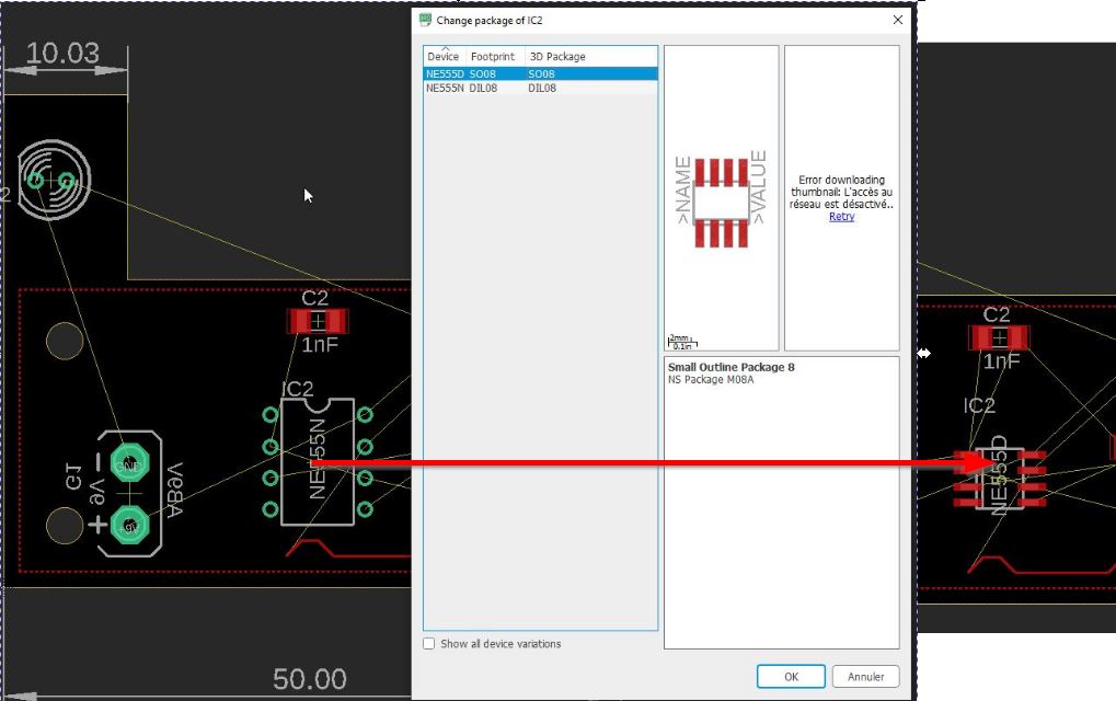
////////////// WARNING
I have made this change, and I had some problems when I restart my project. “Schematic and board are not consistent”
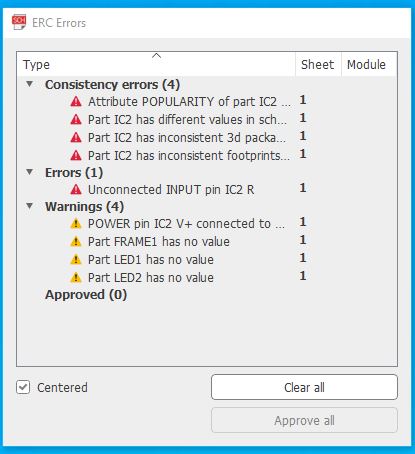
Apparently there was something wrong with the IC2 which is the timer. I came back on the schematic and used the “package” function from RMB. Everything should be clear.
Fan out
I have to go deeply in this field, it seems that
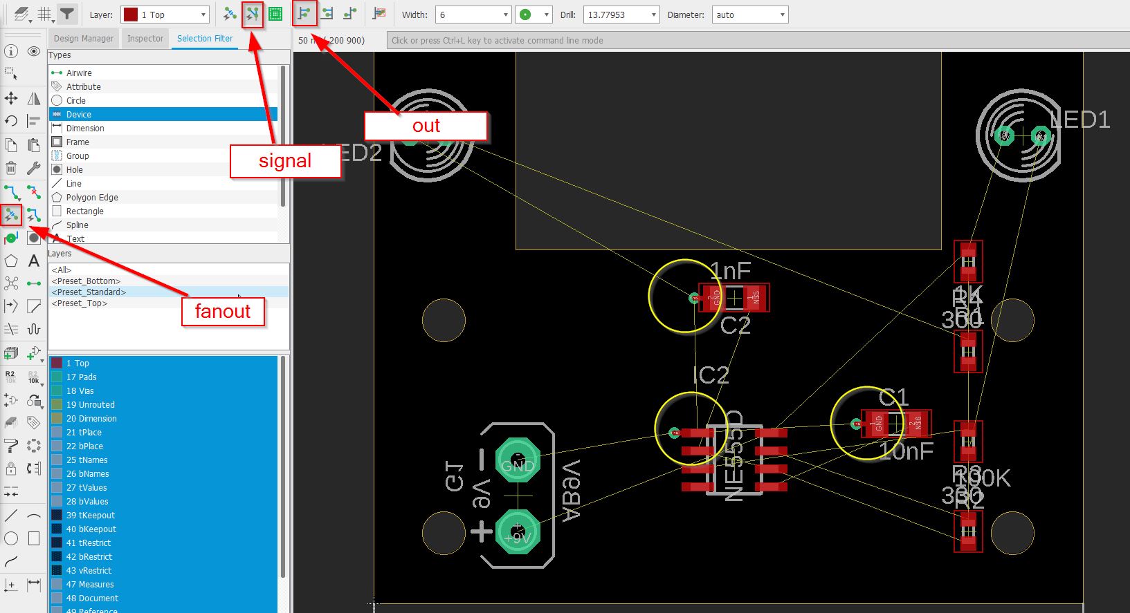
Where GND is somewhere, there will have a VIA.
autorouting.
Autorouting is simply a function to route;
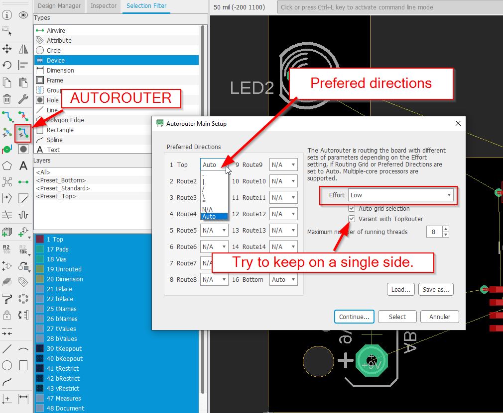
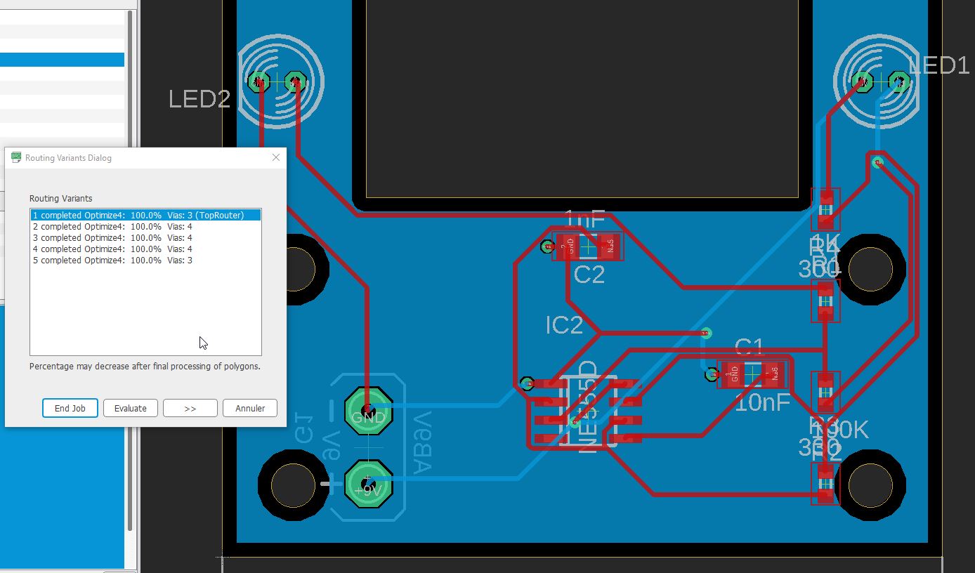
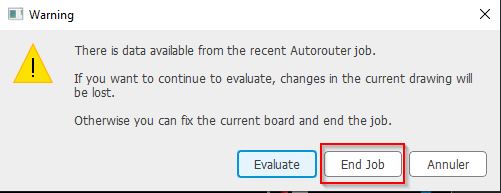
You have different routing variants, select the one you want, (avoid via as much as possible) Click “evaluation” to get an real overview.
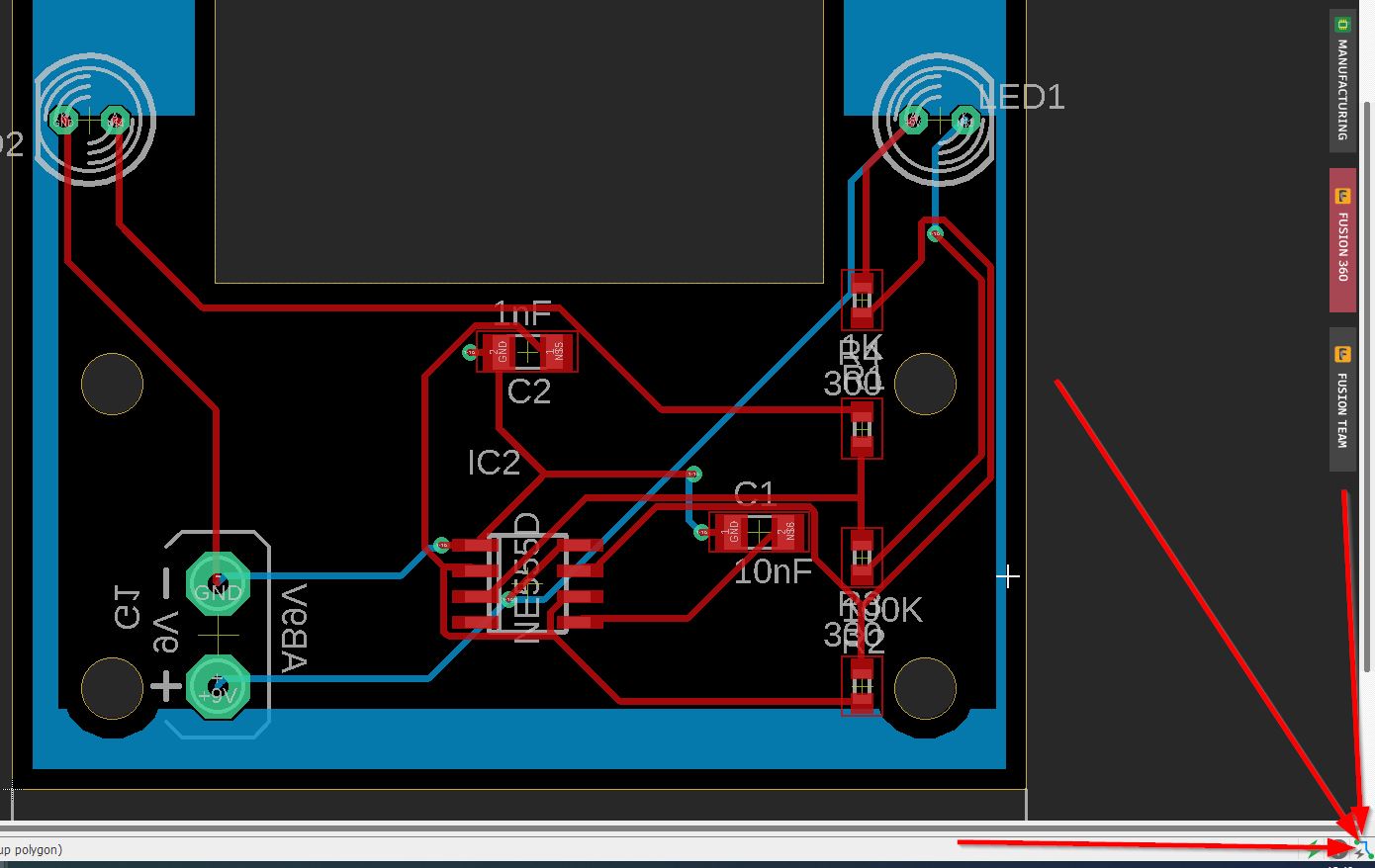
If you are done, click on “end job”.
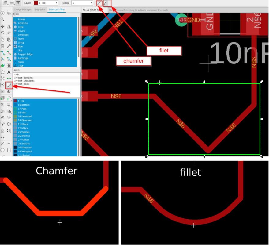
Getting smooth signals.
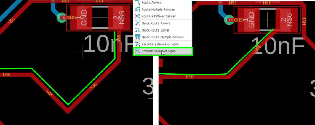
How to miter? (chamfer or fillet)
In my job school, this is STILL the rush for the engineering students for the last study projects.
Tomorrow is the final presentation, after that I will have more time to work on my final project. But I will present my project in january 2022.
Propose a final project masterpiece that integrates the range of units covered
What will it do?
My first idea was to create an entire animated dragon.
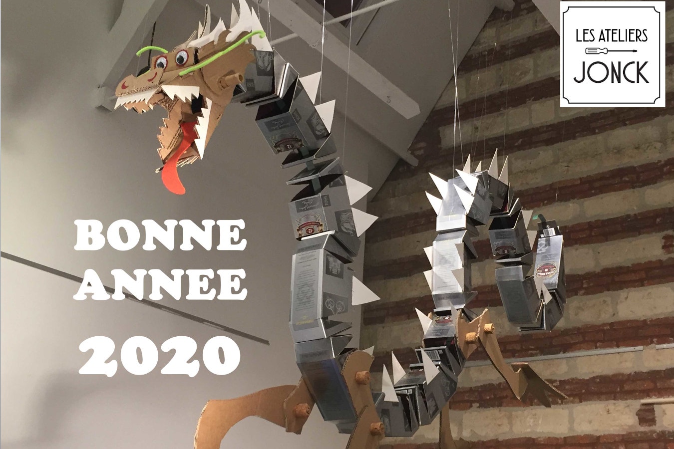
Clic on this link
but time flies, my students are still asking me a lot of advices, so I need to go simple.
In our fablab, I would like to have something to attract all visitors by mixing a lot of fablab techniques. From kids to adults, they will remenber how cool it is to study in an engineering school or to be part of the Fablab communities. My project is to highlight a masterpiece, and I like the works of Leonardo Da Vinci.
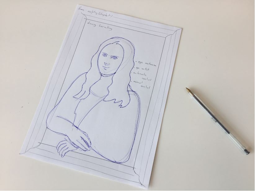
When somebody is passing through Monalisa, her eyes are following you !!
There will have two options: manual and automatic programs. You will be abale to play the “rolling eyes” by using a controller.

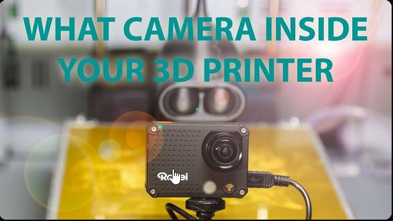
I was thinking also to “have an eye” on the 3D printers in our lab.
Who’s done what beforehand?
A lot of animatronics project have been featured on youtube: such as
[Will cogley]
What will you design?
I take this final project as a beginning to build an entire animatronics.
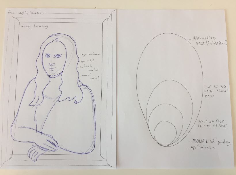
Next level is to get a 3D painting:
What materials and components will be used? How much will they cost?
PLA for 3d rrinted parts ABS sheet for the face. Polyurethane foam for the face core.
Electronics:
Before I was not very attractive by the aliexpress concept, but a lot of students where I work are very comfortable by this cheap electronics platform.
| Qty | Description | link | price |
|---|---|---|---|
| 1 | M2 screws box | amazon | 16.89euros |
| 6 | MG90s servo screws | amazon | 13.99euros |
| 4 | M2 Servo Ball-links | amazon | 6.99euros |
| 6 | MG90s Servos | amazon | 6.99euros |
| 1 | 5V DC supply,1A | amazon | 12.89euros |
| 4 | M2 x 25mm pushrod connectors | amazon | 6euros |
| 1 | ESP-32 camera | amazon | 11.99euros |
| 1 | ESP-32 board | amazon | 9.29euros |
| 1 | ESP-32 chip | RS | 15.83euros |
| 1 | female DC adaptator | [farnell] | 1.0056euros |
| 2 | 2 axis joystick | amazon | 3.63euros |
| 1 | ADAfruit PCA9685 16-channel Servo driver | digikey | 12.37euros |
| 1 | barette | [farnell] | 5euros |
CMS resistors, LEDs, switch button are coming from the fablab.
Product:
| Parts | material | prices | Link |
|---|---|---|---|
| Eye mechanism | PLA | 20 euros | tizyx |
| Frame | plywood 18mm | 20euros | [leroy Merlin] |
| Painting | plywood 5mm | 6euros | [Leroy merlin] |
TOTAL around 170euros.
What parts and systems will be made?
The goal is to adapt the eye mechanism to a piece of Art.
Electronics:
The input and output boards were already done, but I would like to create a bluetooth remote control (close to Playstation controller)
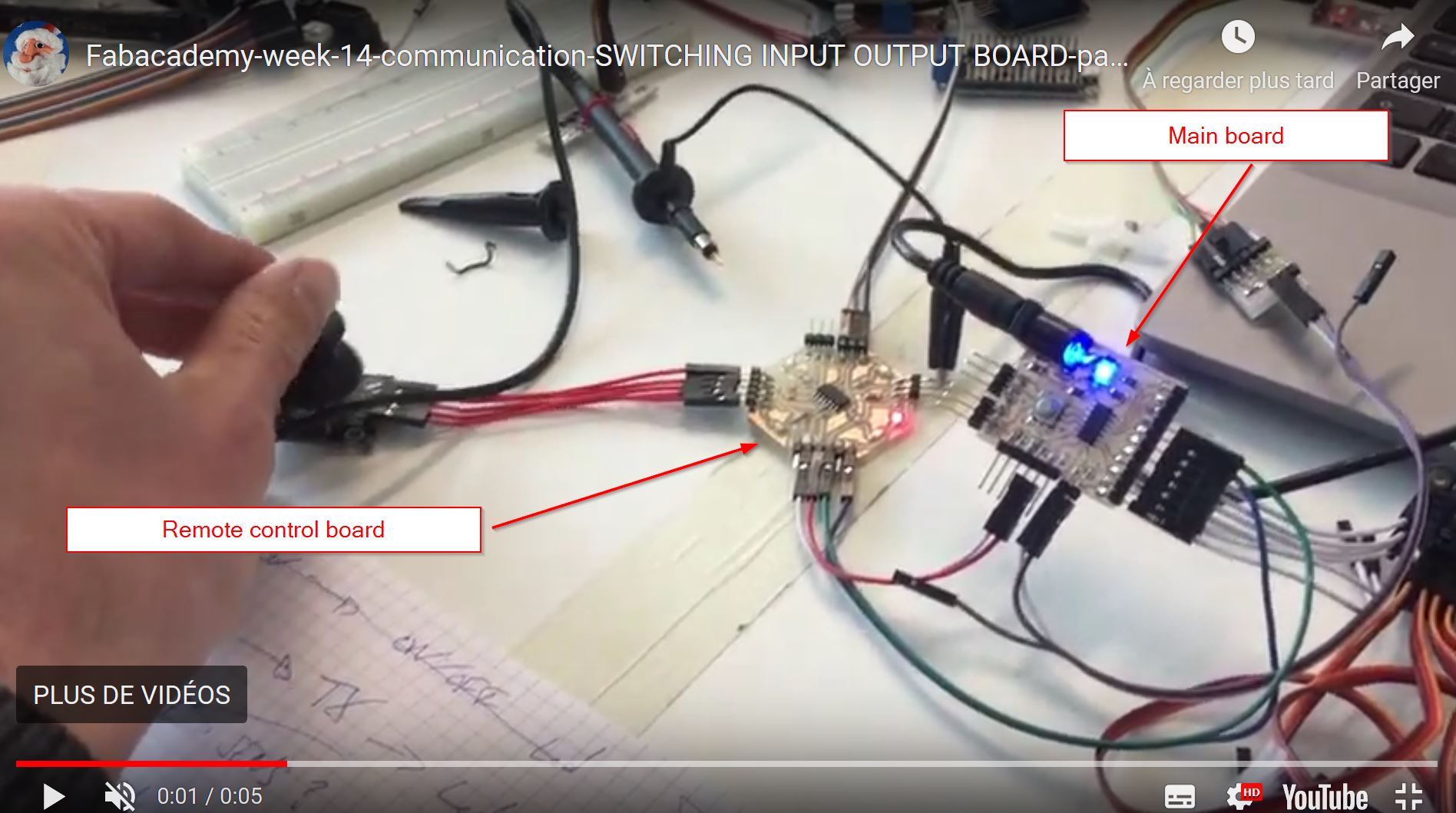
This is on going, I am waiting for my last components to make the board.
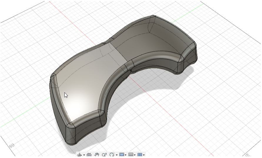
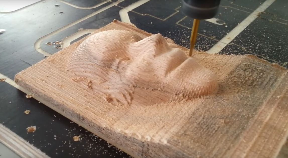
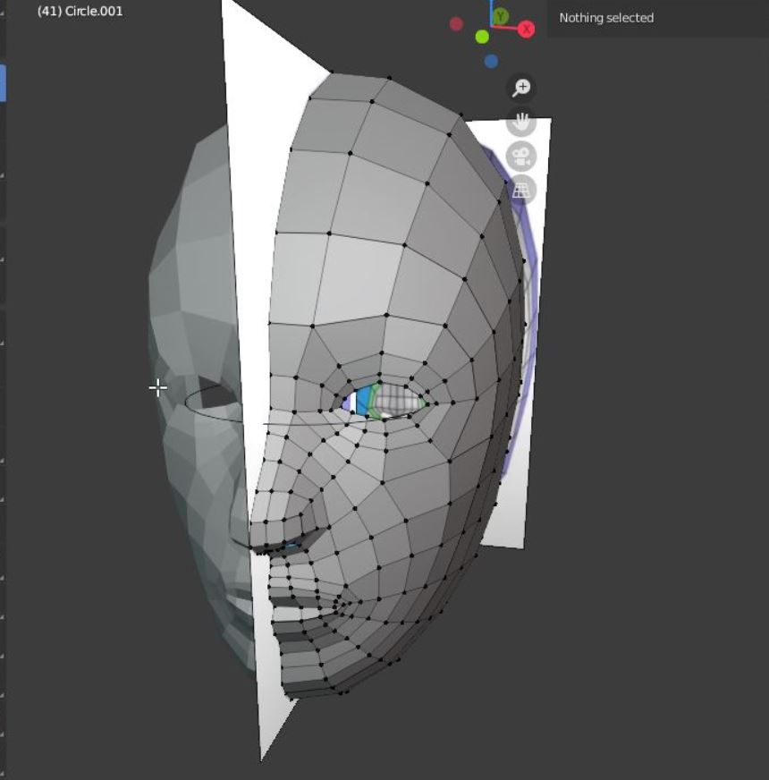
I have started to model on blender a face. But I need to get deeper but for the presentation, I will make the painting first.
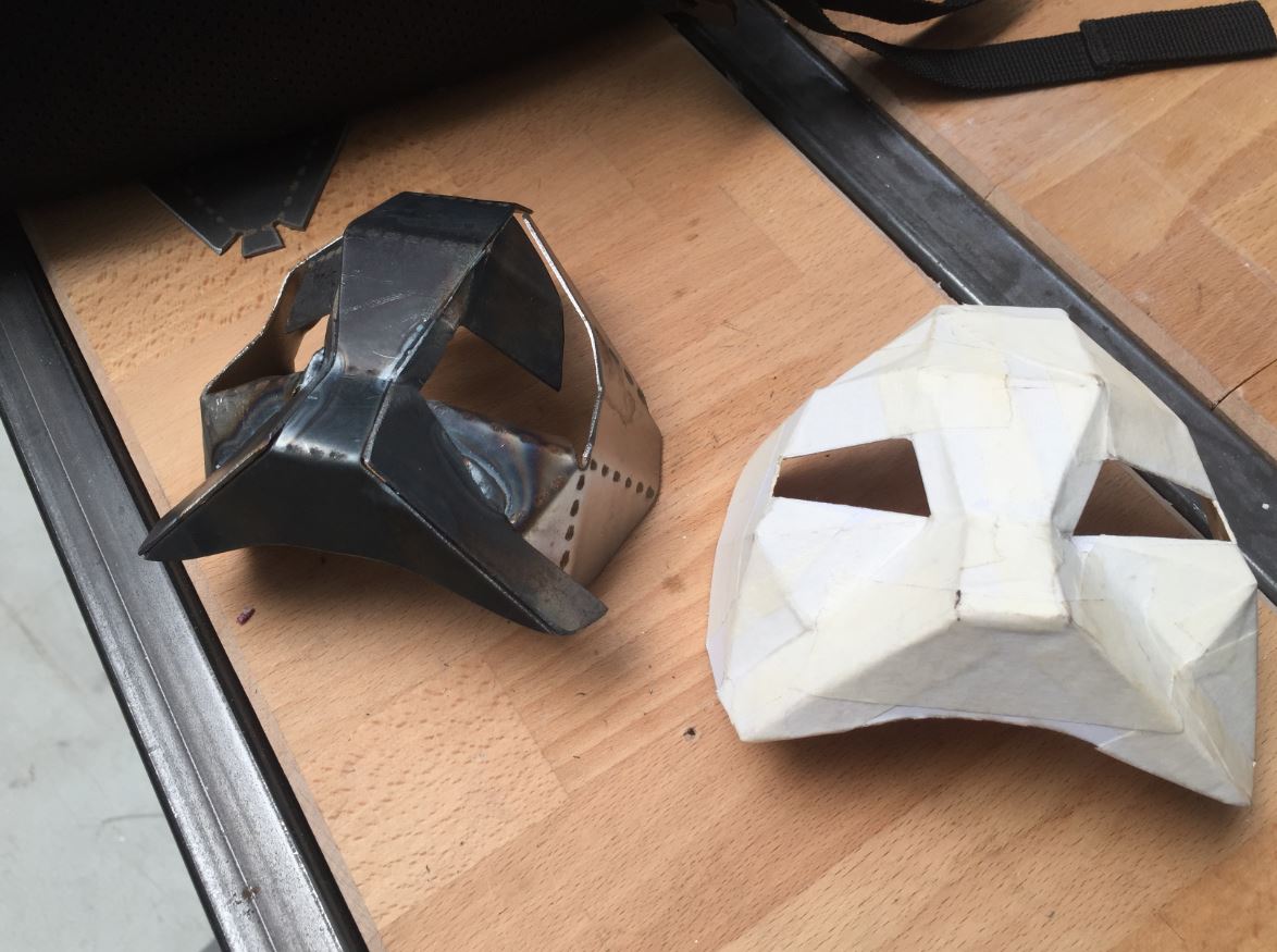
For the next Step, I take advantage of the wildcard week in order to make a steel mask. But It will be for the next level.
I need to get back to resine, the one I use for the eye was a [FAIL]
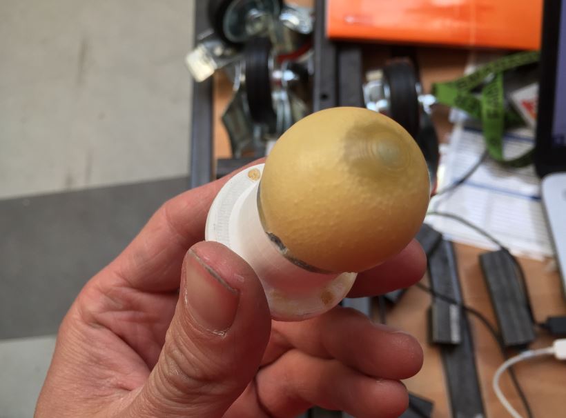
The eye mechanism still need improvements.

The ATTINY 1614 first version:

What processes will be used?
|Frame| shopbot| |Eye mechanism |3d printing| |Painting| lasercutting/engraving|
What questions need to be answered?
Going deeper on programming: Bluetooth control.
The goal of this project is for me to get knowledges on :
Programming C.
Accurency mechanism.
How will it be evaluated?
make it work!
cool links:
https://fabacademy.org/2022/labs/waag/MM2/