11. Input devices
After an overview of the different input devices, I am working on the ones I need for my final project.
Research
My robotic eyes moving need:
- A potentiometer to level the “eyelids”
- A HW-504 joystick
- A switch button for eyes blinking will be on this input device.
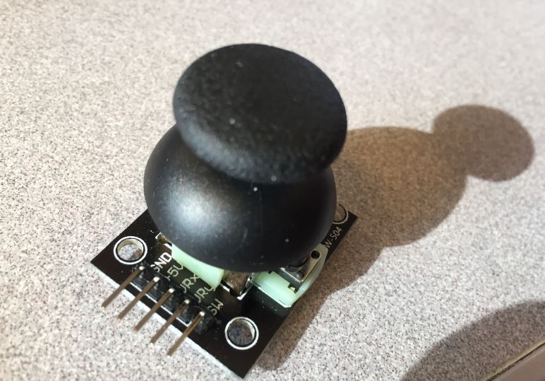 Hw-504 joystick
Download: HW-504 datasheet
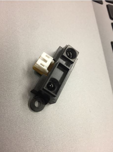
- A distance Sensor: Sharp OA41SK F 89
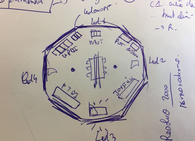
In order to reuse the microprocessor, 3x1 header pins will be used to connect the inputs.
As a response, I will add 4 red Led lights in order to create some basic effects. Here comes the first sketch of my new board:
For the two first electronics assignments, I was not really comfortable at all and I just followed the tutorial. I hav learnt more about theory, so I wanted to create my own board.
reference: According to the datasheet,

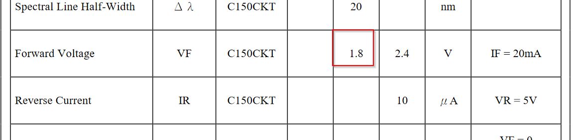
My Leds work for I=40mA and V=1,8V
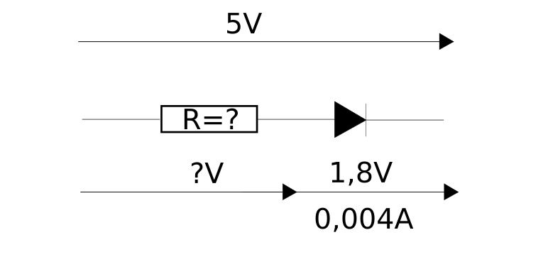
First rule:
Vtot = Vresistor + Vled
5V = Vresitor + 1,8V
Vresitor = 3,2V
Second rule:
“V = R*I”
“R = V/I”
“R = 3,2/0,004 ==> R = 80 Ohms “
Elecronics buddies advices me to increase the resistor for preventing the leds from current. so I haved chosen 200 ohms ones.
For my two last electronics assignments, the microprocessors were ATTINY 85 and ATTINY 44.
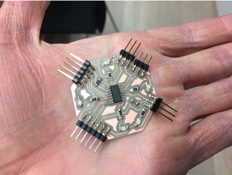
Attiny 1614 should host all my components:
Download: ATTINY1614 datasheet
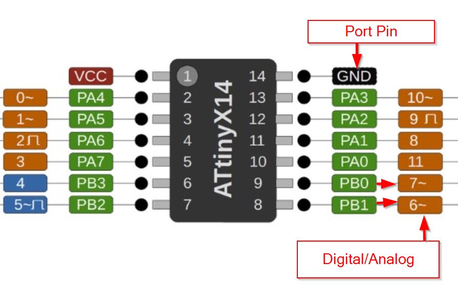
Jules Topart gave me tricks about the datasheet and pinouts. ADC equals Analog- Digital - converter, which means the pin to plug my potentiometer.

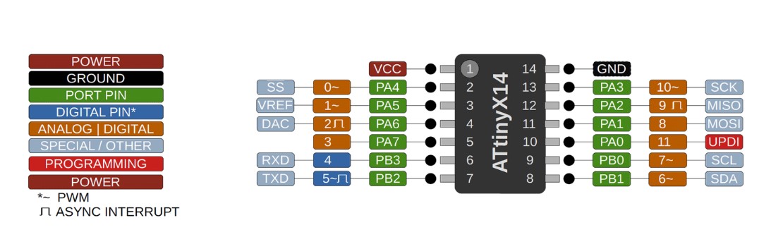 |inputs | pinouts|
| :--------------- |:---------------:|
|pot|PA4|
|hw-504 joystick|PA5 -PA6|
|hw-504 switch |
|inputs | pinouts|
| :--------------- |:---------------:|
|pot|PA4|
|hw-504 joystick|PA5 -PA6|
|hw-504 switch |
My colleagues Jules and Sylvain advised me to move from FabIsp programmer to UPDI board. This “UPDI” is a way to program the attiny MP according to one pin instead of using 3 pinnouts. I will create this board as well.
Back to Eagle
There are some new things I learnt:
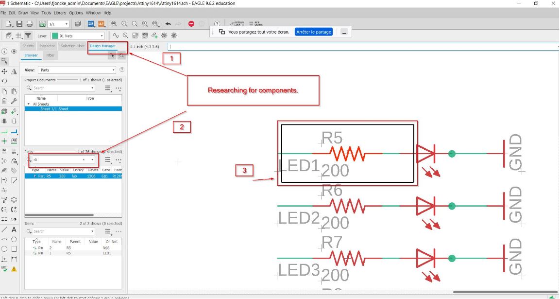
Research of components:
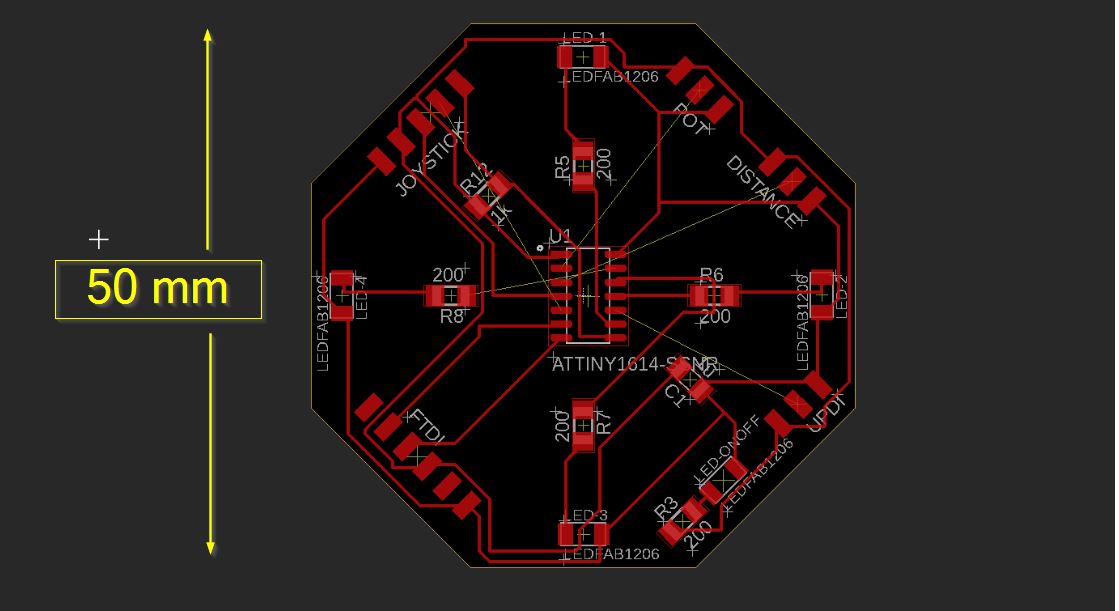
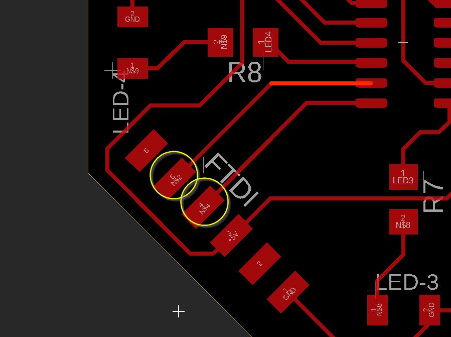
Here comes the schematics:
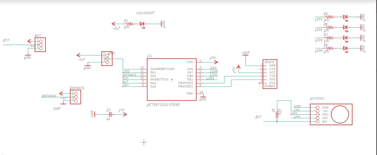
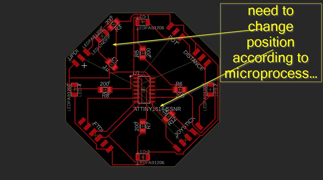
To avoid any “dead end”, I have changed the direction of the joystick.
Inkscape
export png 2000px
Routing
We use the sain
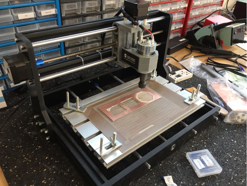 For this week
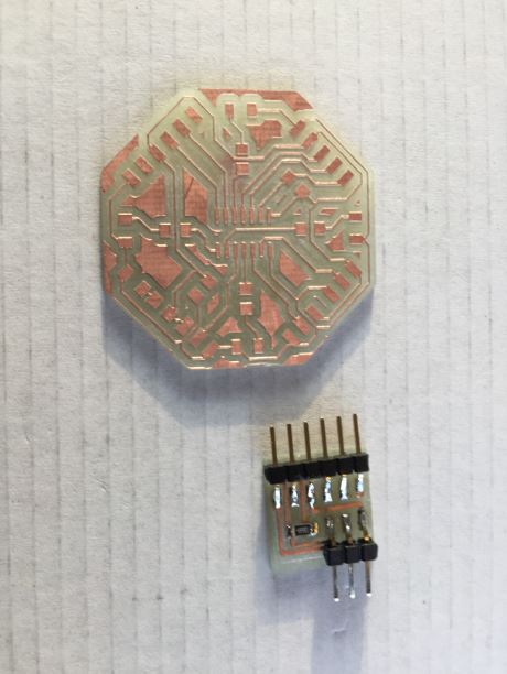
soldering
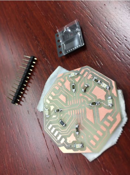
Voilà !
programming.
I have used the UPDI programmer.
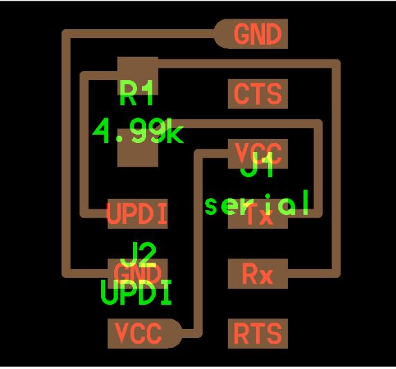
And set up the ttl programmer and my Attiny1614 board.
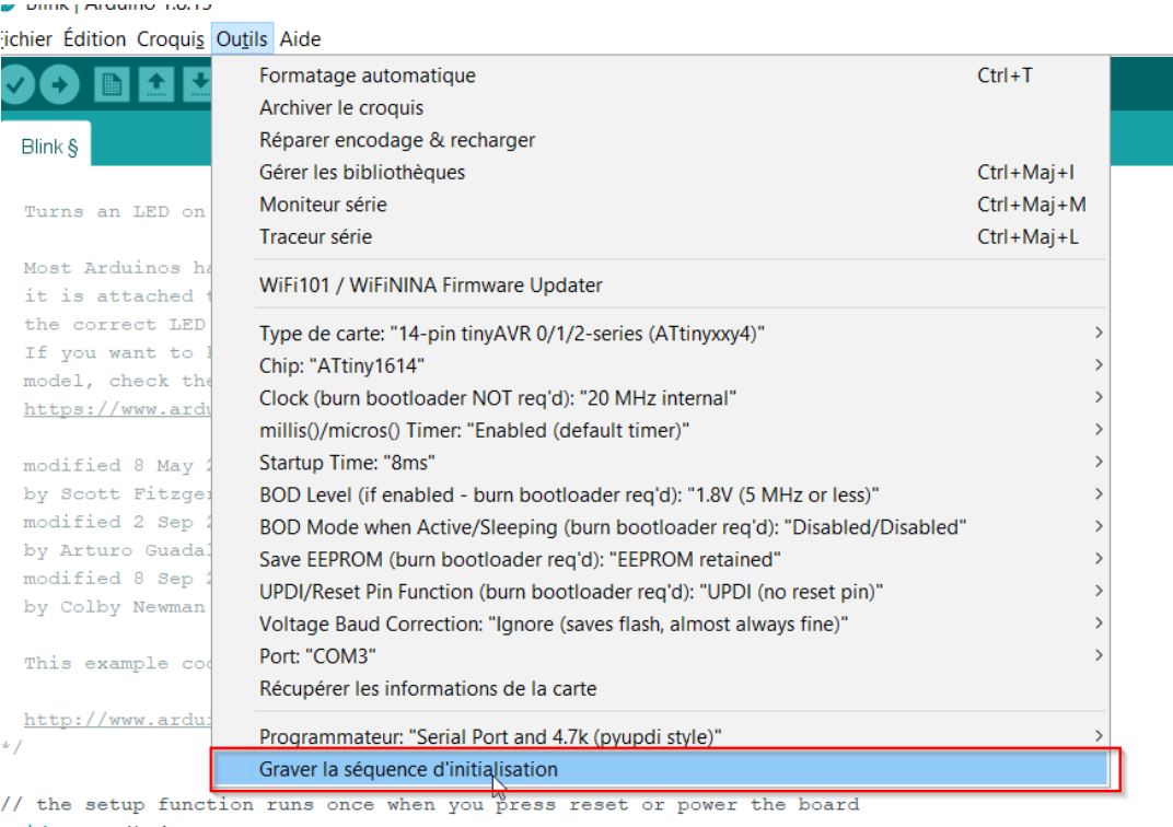
BOOTLOADER
What’s a bootloader? More info on Arduino Microcontrollers are usually programmed through a programmer unless you have a piece of firmware in your microcontroller that allows installing new firmware without the need of an external programmer. This is called a bootloader.
Select the proper MC: ATTINY1614.
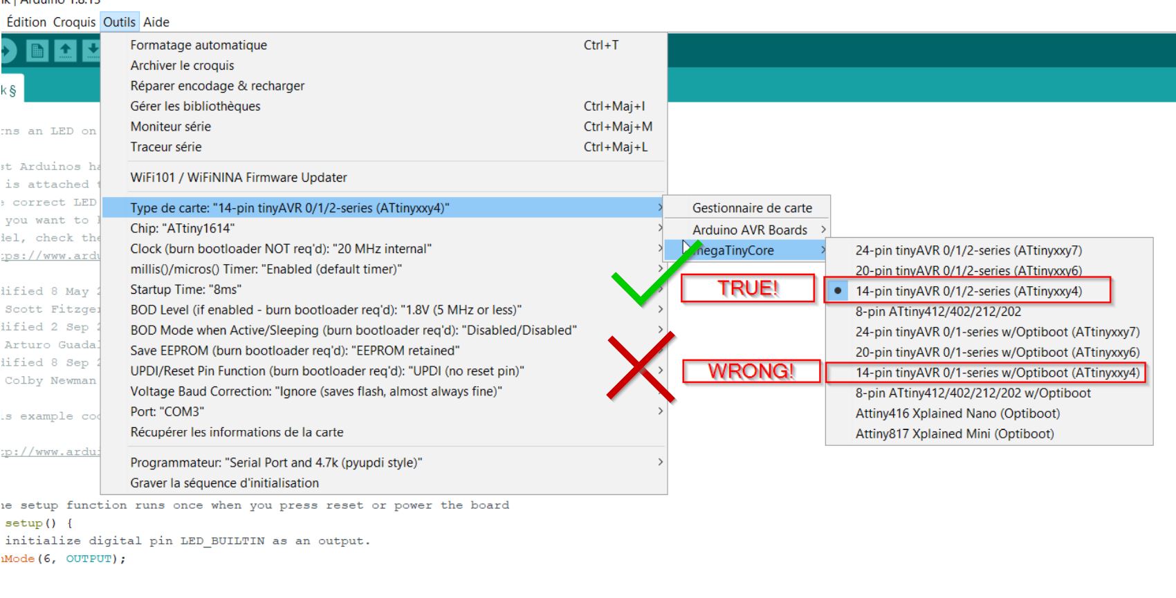
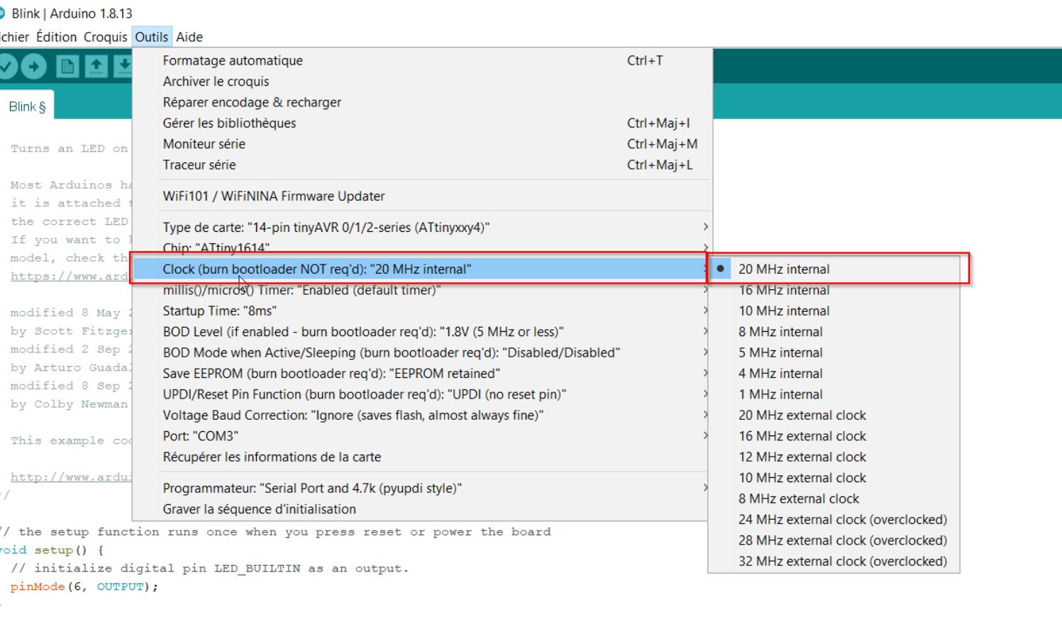
Select the proper clock.
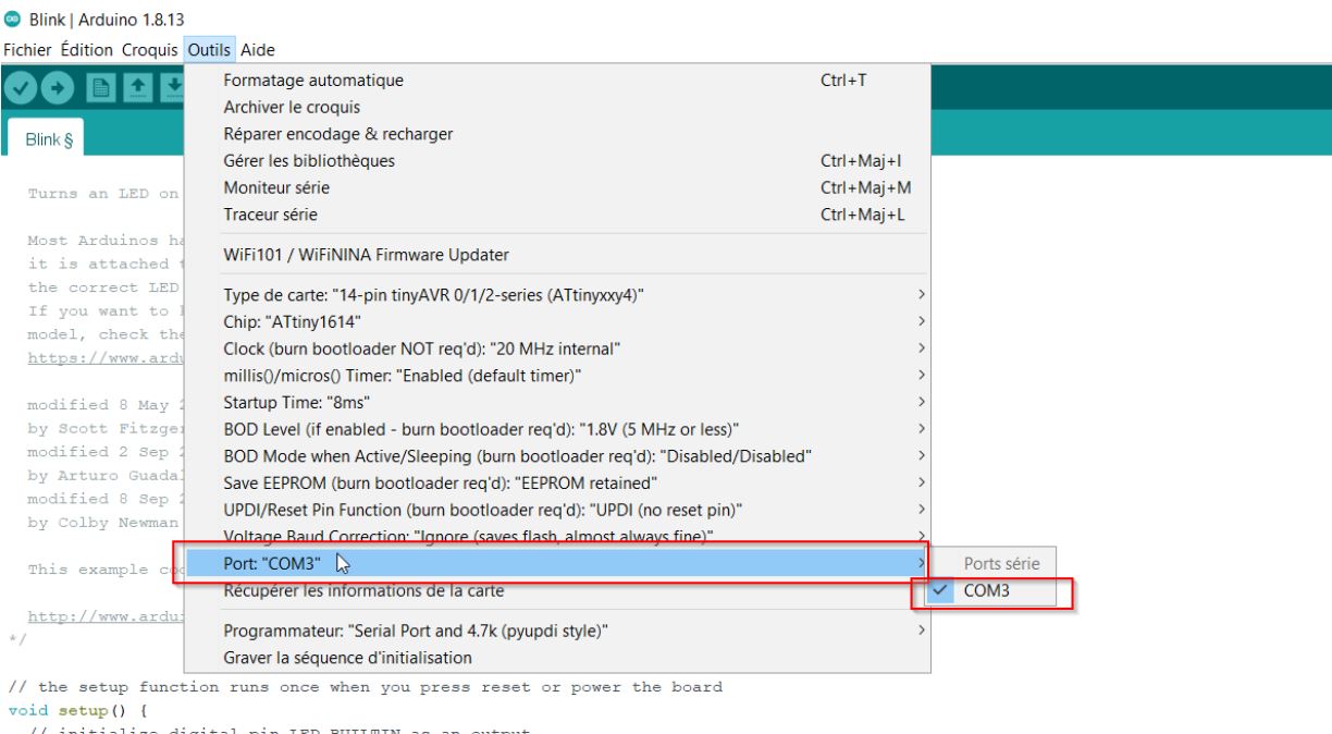
Select the proper port.
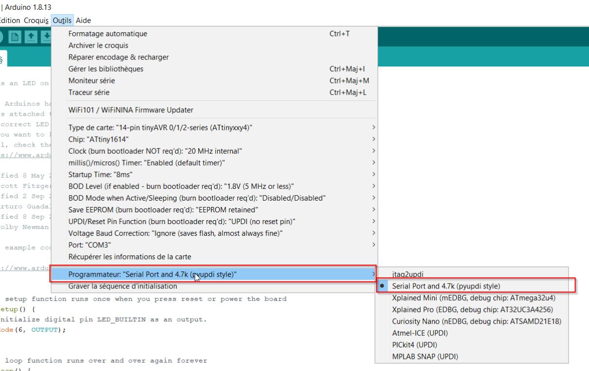
Select the proper programmer:
3,2,1… BOOTLOADER!!
Coding
First example: 4 LEDs blinking
I would like to use the leds and make an LED chase effect.
Pin number for the first LED (LED1) is PA1 on datasheetPA4 but it equals A4 in ARDUINO.
#define Led1  A1
#define Led2  A7
#define Led3  B0
#define Led4  B1

void setup()
{
  pinMode(Led1, OUTPUT);
  pinMode(Led2, OUTPUT);
  pinMode(Led3, OUTPUT);
  pinMode(Led4, OUTPUT);
}

void loop() // Boucle infinie
{
  digitalWrite(Led1, HIGH);
  delay(100);
  digitalWrite(Led1, LOW);
  delay(100);

    digitalWrite(Led2, HIGH);
  delay(100);
  digitalWrite(Led2, LOW);
  delay(100);

    digitalWrite(Led3, HIGH);
  delay(100);
  digitalWrite(Led3, LOW);
  delay(100);

    digitalWrite(Led4, HIGH);
  delay(100);
  digitalWrite(Led4, LOW);
  delay(100);
Only two leds have blinked. I have checked 0.6V on the multimeter on each led. I think the pin name is not good. After the local review, Stéphane Muller from La Sorbonne advised me to change the pin names to the analog/digital ones. B0 ==> 7 B1 ==> 6
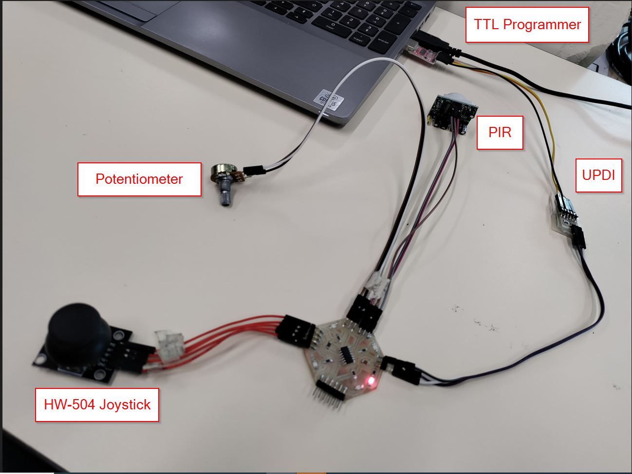
Potentiometer.
I have uploaded a program to get feedbacks from the serial port.
void setup() {
   Serial.begin(9600);  // ouvre le port série
   pinMode(A3, INPUT);
}

void loop() {
   int val = analogRead(A3);  // lit la valeur actuelle du potentiomètre

   Serial.println(val);
   delay(500);  // attend 500 ms
}
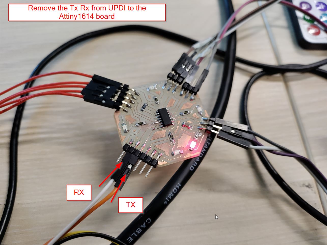
I got nothing at the serial port. Stephane from La Sorbonne told me to remove the updi to let tx and rx going to the tx rx pins (which are located on pin 7 and 8)
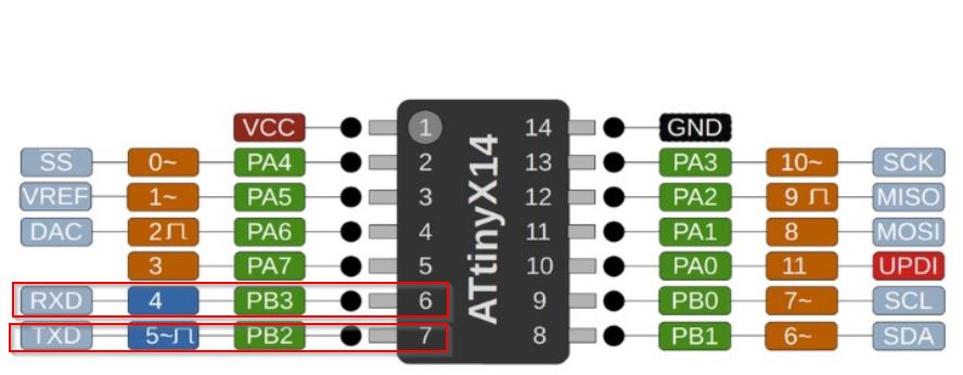
and check on the schematics on Eagle!
And unplug and plug to the board.
I got what I wanted. From 0 to 1023, I can see on the serial port.
I am trying to change the lightness of my led.
void setup() {
   pinMode(A1, OUTPUT);
   pinMode(A3, INPUT);
}

void loop() {
   int val = analogRead(A3);  // lit la valeur actuelle du potentiomètre

   val = val / 4;
   analogWrite(A1, val);
}
It works!!
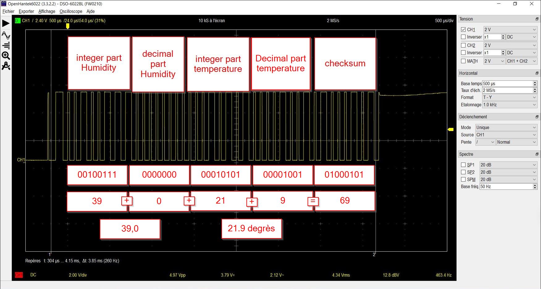
DHT 11 Humidity
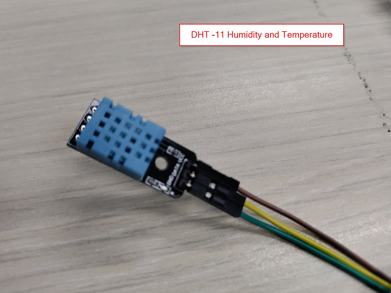
Install library for the component:
 In this library, there are plenty of functions according to this sensor. In the code, we will start with the #include “DHT.h”
#include "DHT.h"
DHT dht(2, DHT11);

void setup() {
   dht.begin();
   Serial.begin(9600);
}

void loop() {
   float h = dht.readHumidity();
   float t = dht.readTemperature();

   Serial.print("Humidity: ");
   Serial.println(h);
   Serial.print("Temperature: ");
   Serial.println(t);
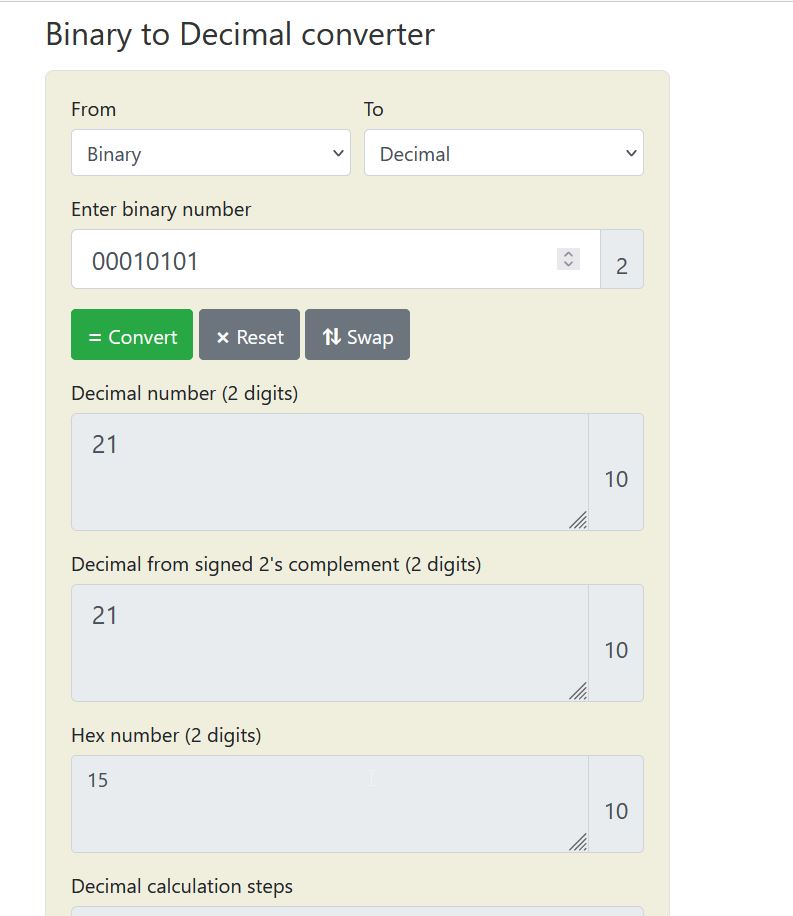
Analysing on the oscilloscope:
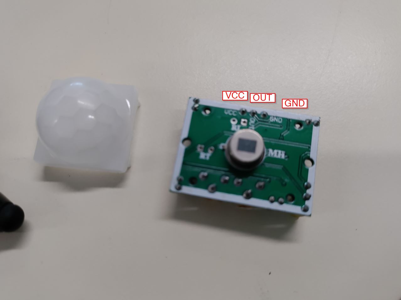
PIR
Heat source movement.
infos :https://learn.adafruit.com/pir-passive-infrared-proximity-motion-sensor/how-pirs-work
I would like to get some feedbacks, and the serial port is not working.
SO I am going to use Arduino Uno to get something.
//initialisation de la pin 2
int Capteur=2;

void setup() {
  pinMode(Capteur,INPUT);//définir la pin 2 comme une entrée
Serial.begin(9600);
  pinMode(13,OUTPUT);

}

void loop() {
  if(digitalRead(Capteur)==HIGH){ //le capteur détecte un mouvement
    Serial.println("mouvement detecte");
        digitalWrite(13,HIGH);
    delay(5000);
  }
  else{//sinon le capteur ne détecte aucun mouvement
    Serial.println("pas de mouvement detecte");
  }
  delay(200);
  }
  // put your main code here, to run repeatedly:
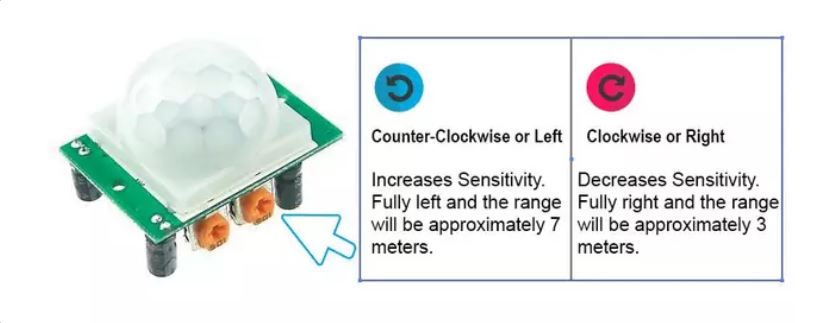
There are two potentiometers to adjust parameters:
4x4 Keypad
The keypad is a set of buttons arranged in rows and columns.(called Matrix) Each button is called a key. - more infos
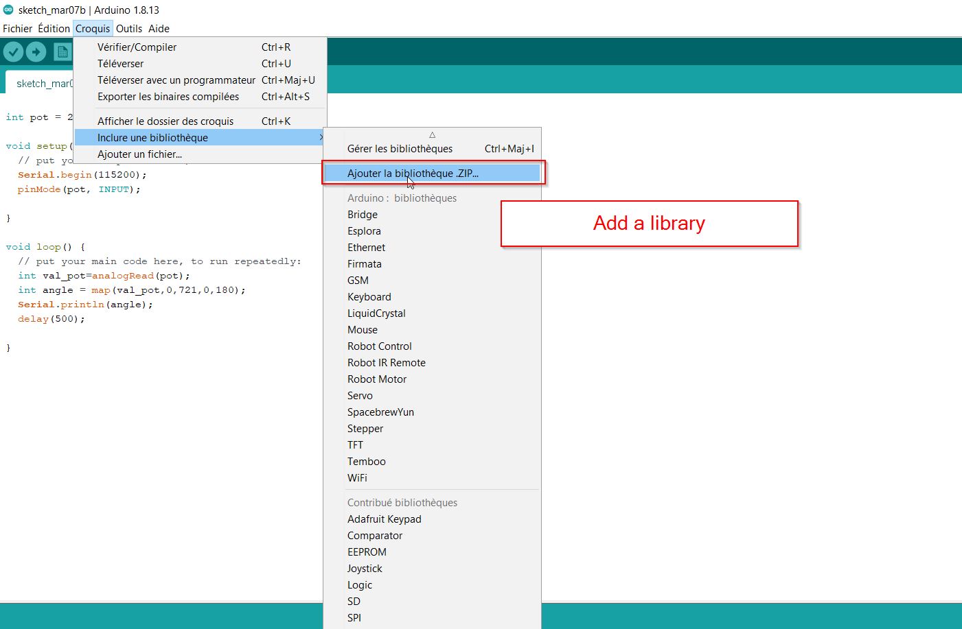
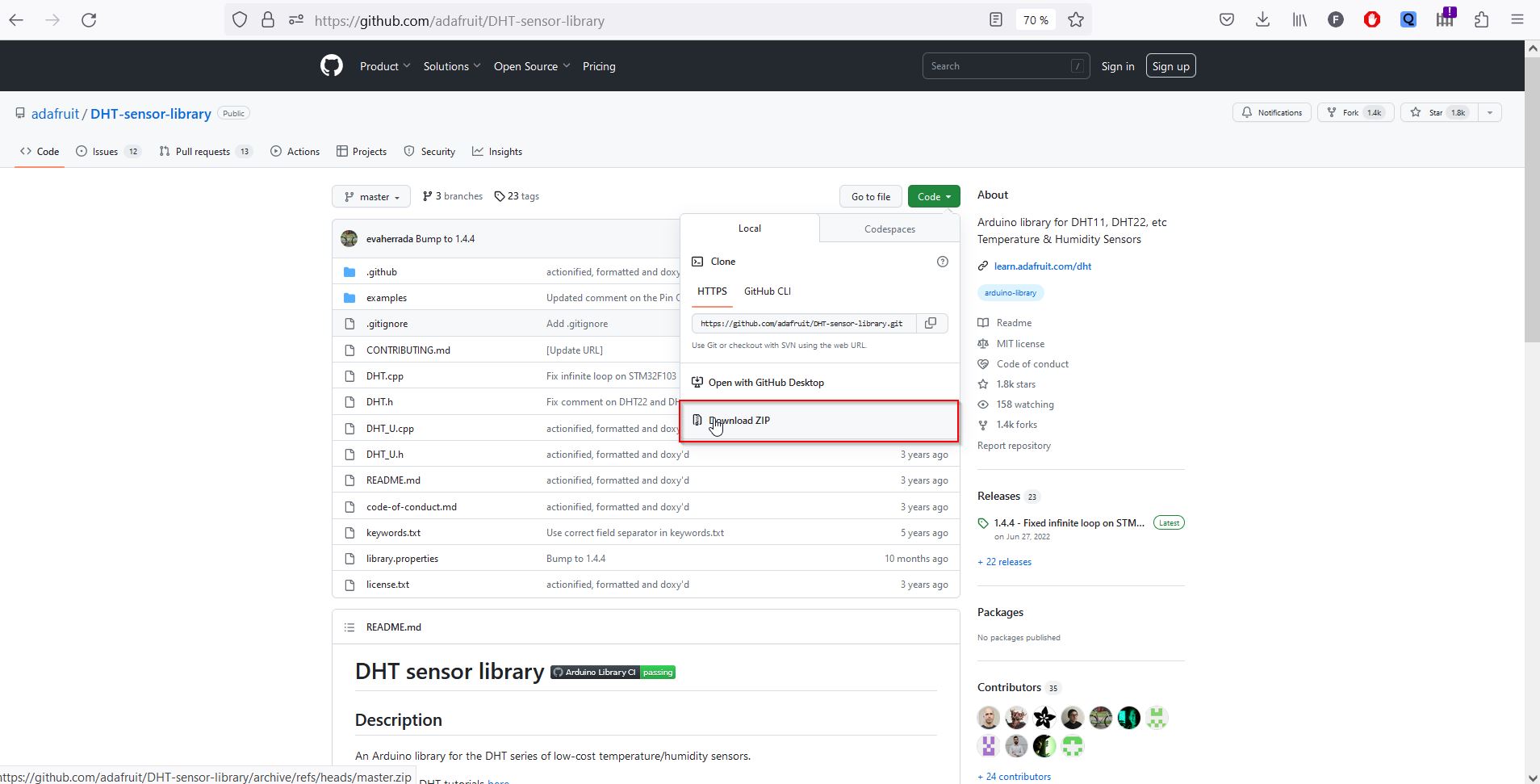
You have to install the library as well.
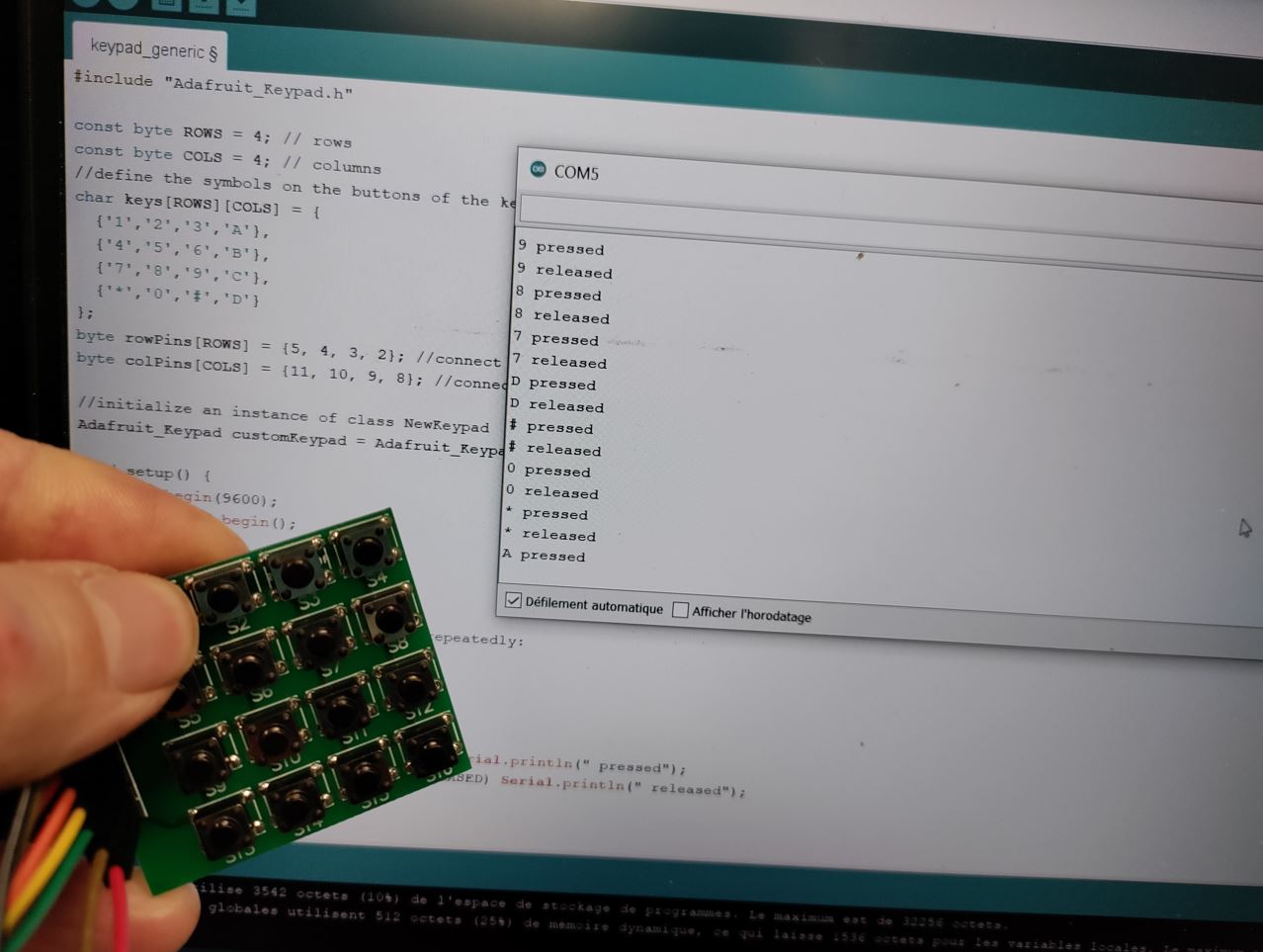
#include "Adafruit_Keypad.h"

const byte ROWS = 4; // rows
const byte COLS = 4; // columns
//define the symbols on the buttons of the keypads
char keys[ROWS][COLS] = {
  {'1','2','3','A'},
  {'4','5','6','B'},
  {'7','8','9','C'},
  {'*','0','#','D'}
};
byte rowPins[ROWS] = {5, 4, 3, 2}; //connect to the row pinouts of the keypad
byte colPins[COLS] = {11, 10, 9, 8}; //connect to the column pinouts of the keypad

//initialize an instance of class NewKeypad
Adafruit_Keypad customKeypad = Adafruit_Keypad( makeKeymap(keys), rowPins, colPins, ROWS, COLS);

void setup() {
  Serial.begin(9600);
  customKeypad.begin();

}

void loop() {
  // put your main code here, to run repeatedly:
  customKeypad.tick();

  while(customKeypad.available()){
    keypadEvent e = customKeypad.read();
    Serial.print((char)e.bit.KEY);
    if(e.bit.EVENT == KEY_JUST_PRESSED) Serial.println(" pressed");
    else if(e.bit.EVENT == KEY_JUST_RELEASED) Serial.println(" released");
  }

  delay(10);
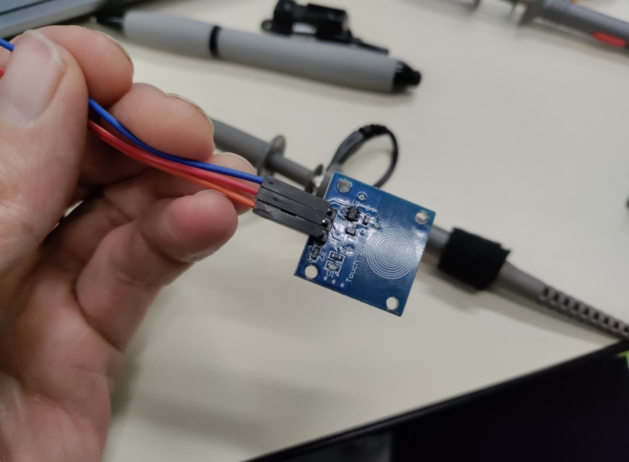
sensor touch
TOuch sensor (also called touch button or touch switch) is used to control devices . It has the same functionality as a button. GND pin needs to be connected to GND. Vcc pin needs to be connectdd to Vcc Signal is an ouput pin.
// constants won't change. They're used here to set pin numbers:
const int SENSOR_PIN = 7; // the Arduino's input pin that connects to the sensor's SIGNAL pin


// Variables will change:
int lastState = LOW;      // the previous state from the input pin
int currentState;         // the current reading from the input pin

void setup() {
  // initialize serial communication at 9600 bits per second:
  Serial.begin(9600);
  // initialize the Arduino's pin as aninput
  pinMode(SENSOR_PIN, INPUT);
  pinMode(13,OUTPUT);
}

void loop() {

  digitalWrite(13,LOW);

  // read the state of the the input pin:
  currentState = digitalRead(SENSOR_PIN);

  if(lastState == LOW && currentState == HIGH){
    Serial.println("The sensor is touched");
    digitalWrite(13,HIGH);
    delay(5000);
  }

  // save the the last state
  lastState = currentState;
}
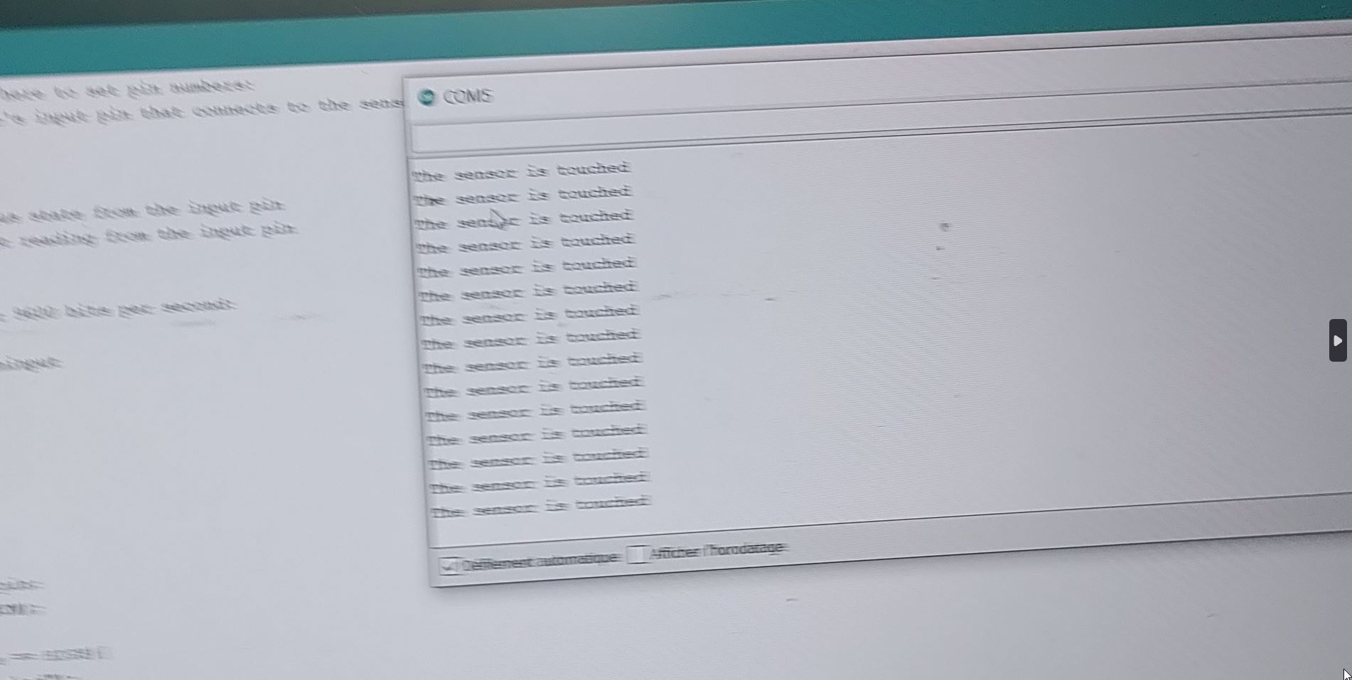 The sensor has been touched by my finger!
I have used the oscilloscope to get the signal from the input device.
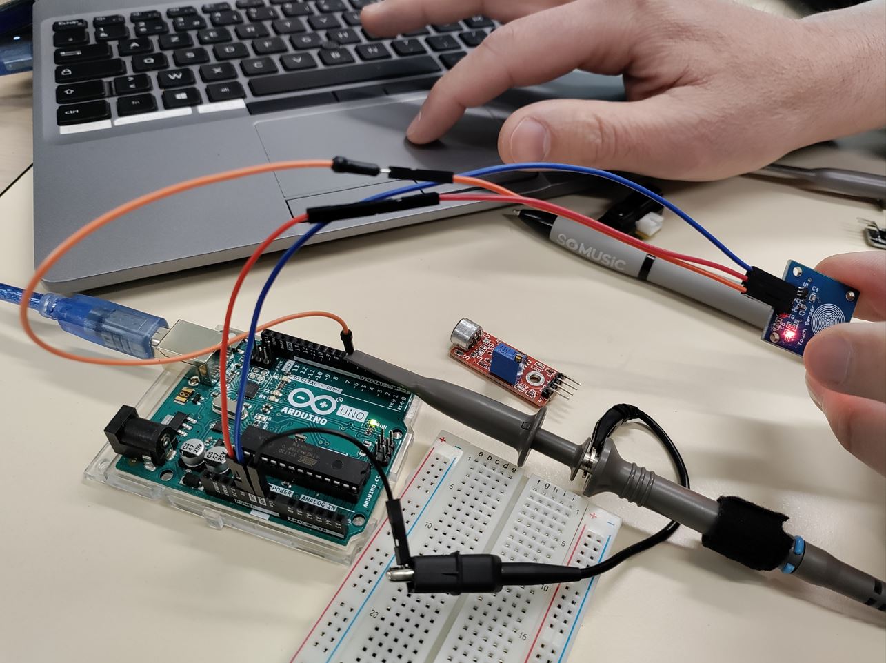
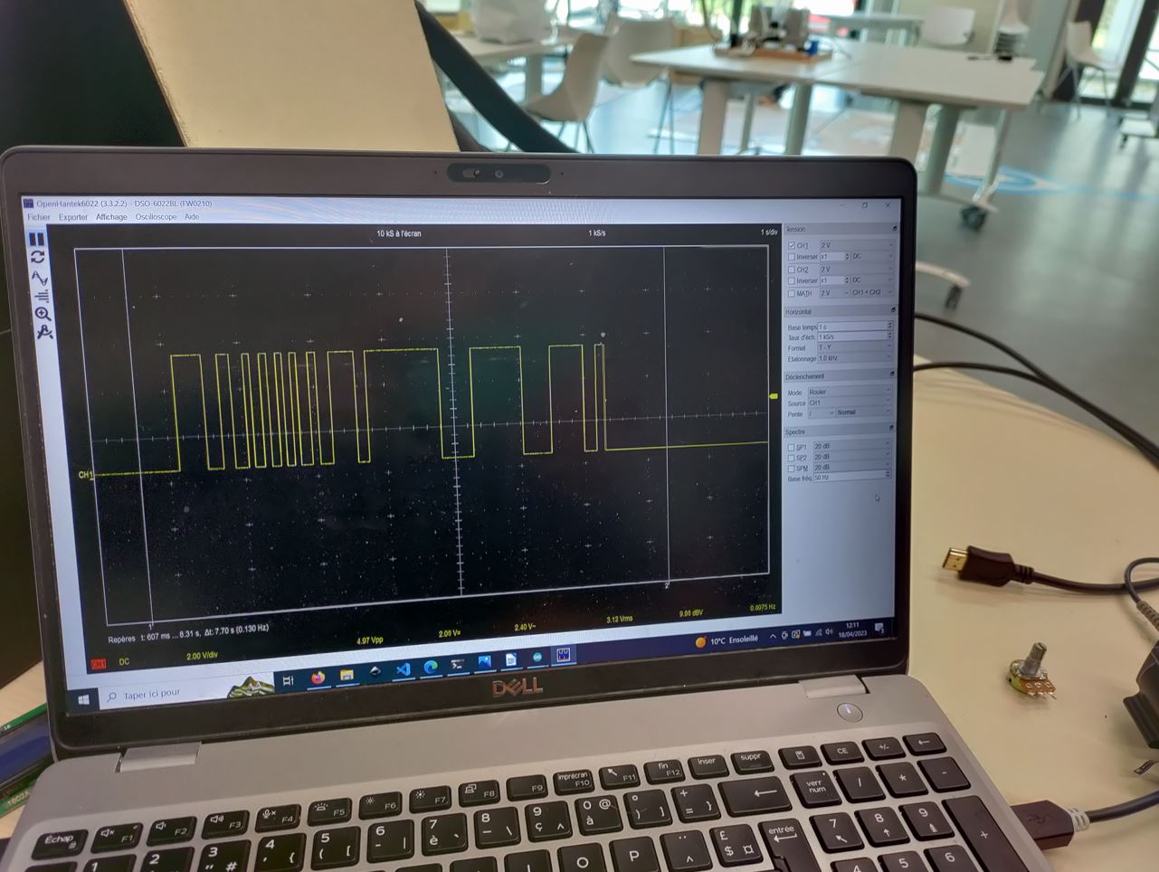
0 no touch 5V touching
Useful links
Code Example
Use the three backticks to separate code.
// the setup function runs once when you press reset or power the board
void setup() {
  // initialize digital pin LED_BUILTIN as an output.
  pinMode(LED_BUILTIN, OUTPUT);
}

// the loop function runs over and over again forever
void loop() {
  digitalWrite(LED_BUILTIN, HIGH);   // turn the LED on (HIGH is the voltage level)
  delay(1000);                       // wait for a second
  digitalWrite(LED_BUILTIN, LOW);    // turn the LED off by making the voltage LOW
  delay(1000);                       // wait for a second
}
Gallery

Video
From Vimeo
Sound Waves from George Gally (Radarboy) on Vimeo.
From Youtube
3D Models
review. dorian from Kamplinfort conductive fabric.