FabAcademy 2021 - Final Project
Presentation
For my final project to complete the Fab Academy program I have decided to work on a Puzzle Box (also called a “Secret Box” or a “Trick Box”). The idea is to manage opening the box as fast as possible by resolving a series of puzzles, and is thus purely for entertainment purposes. Technically this game can be solved by a single person, but it is more fun to tackle it as a team of friends or family, especially as collaboration is often key for success.
Final result
Puzzle Box solving demonstration :
Herebelow are presented the slide and video that summarize all the work I have done during this FabAcademy program to design and produce my puzzle box.
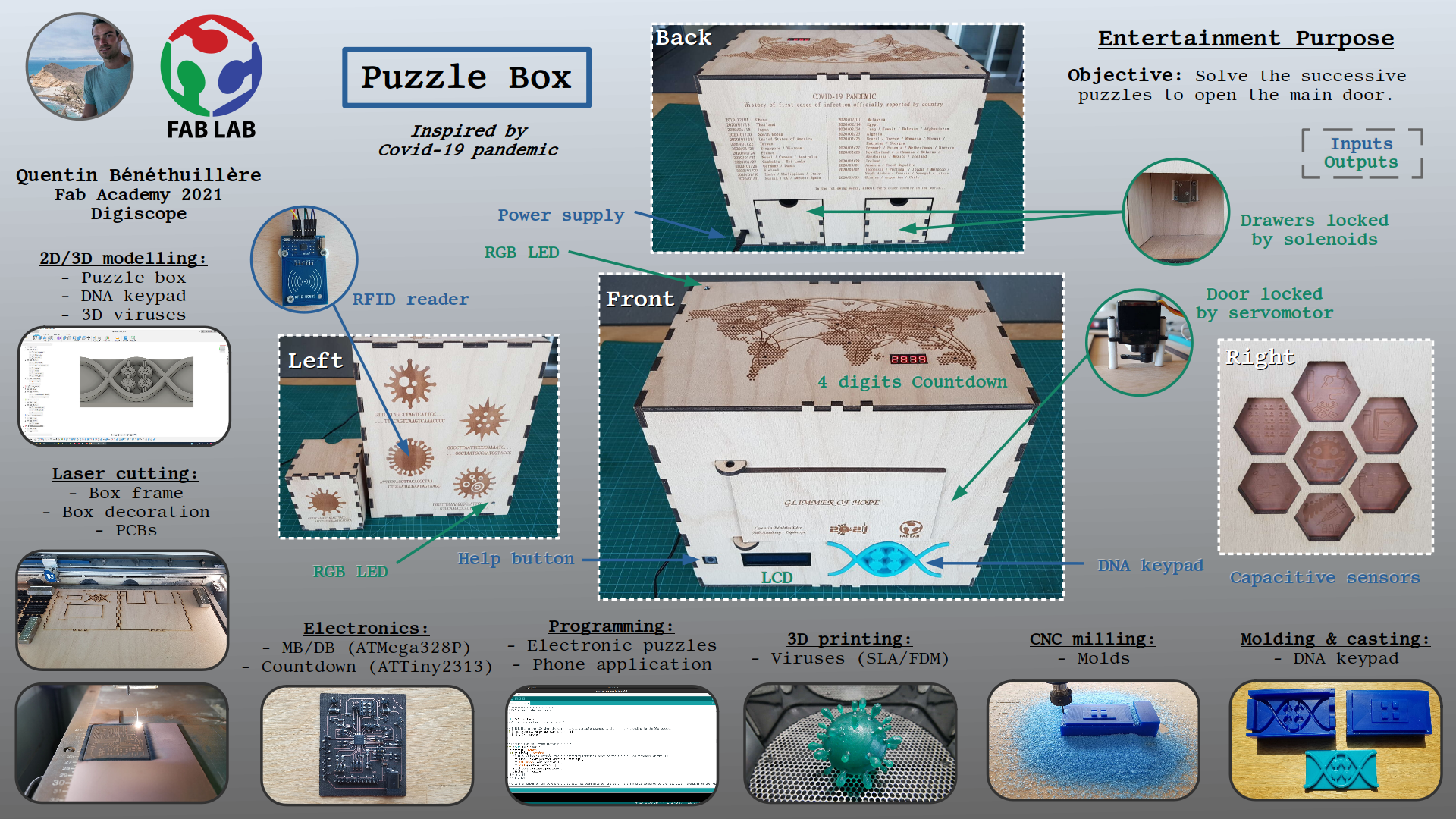
Puzzle box - Presentation slide
The box is made out of beech plywood 5mm and consists of 2 drawers locked by solenoid mechanisms and a main door locked by a servomotor. It features 4 electronics puzzles to be solved :
- Capacitive sensors sequence.
- Wire connections sequence.
- RFID access control.
- Digicode access control.
Additional elements such as engraved text/drawings and 3D printed objects help players to solve the puzzles. A LCD is also used to display messages to guide players throughout their progression in the game, as well as RGB LEDs that act as feedback to players’ actions.
I also designed a phone application that allows to control all the electronics of the puzzle box. This application is not necessary to play the game, however it allows me to send custom messages to players through the LCD, and also to make sure that all lock mechanisms are operational before players start the game.
Motivation
As mentioned in the “About Me” section, I like playing all sorts of games, and among those I had the chance to participate in a dozen of escape room adventures. The idea is very much similar to the Puzzle Box in the sense that participants have a certain amount of time to resolve a series of puzzles to complete a given mission, with the main difference that participants are physically locked in one or several rooms, which definitely offers a more immersive experience.
I am really keen on those type of adventures because your brain is solicited to such an extent that after only a few minutes playing you feel completely focused in the mission that has been assigned to you. Moreover tricks are usually so complex that all players ideas are necessary to lead the team to the success. Communication and collaboration are of paramount importance, and this explains why those games are frequently chosen for team building events.
With my Puzzle Box, I wish I can offer to my family and friends a very special moment together. This project may also be an excellent opportunity for me to continue working on such mechanisms on my own or even for joining a company involved in those activities.
Game scenario
As fablab active members, your team is convinced that globally sharing knowledge is the only way to save humanity, especially in a time of pandemic crisis. After several weeks of preparation and thanks to your precious skills in digital fabrication you have successfully managed at night to break in the “Covid 19 Task Force Room” of one of the world’s biggest pharmaceutical company who recently officially announced positive results with the vaccine they developed against Covid-19. Your goal is to get ahold of the vaccine manufacturing method to share it around the world so that the vaccine can be produced everywhere and in sufficient quantities in many local labs to stop the pandemic before it is too late. Money should definitely not be the primary source of concern in such a situation ! After few minutes of inspection in this room, it seems that you have located a safe where the vaccine manufacturing method could well be stored. Look closely for any information that could help you opening this safe, but be careful as some security mechanisms have most likely be implemented to protect it.
Think hard and hurry up to get your mission completed, you are at risk here!
Solution
Puzzle 1 : Capacitive sensors sequence
To solve this puzzle successively press on the capacitive sensors in the order indicated below :
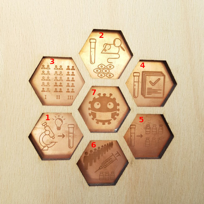
Puzzle 1 - Solution for capacitive sensors sequence
- Research on a vaccine against Covid-19 virus.
- Animal testing.
- Human testing (phase 1, phase 2 and phase 3).
- Approval of the authorities.
- Production.
- Mass vaccination.
- End of covid-19 pandemic (virus muted).
Consequence : Unlocks the left drawer that contains a 3D printed virus (green one) and some short electrical wires. Inside the 3D printed virus is hidden a longer electrical wire that allows to complete next puzzle.
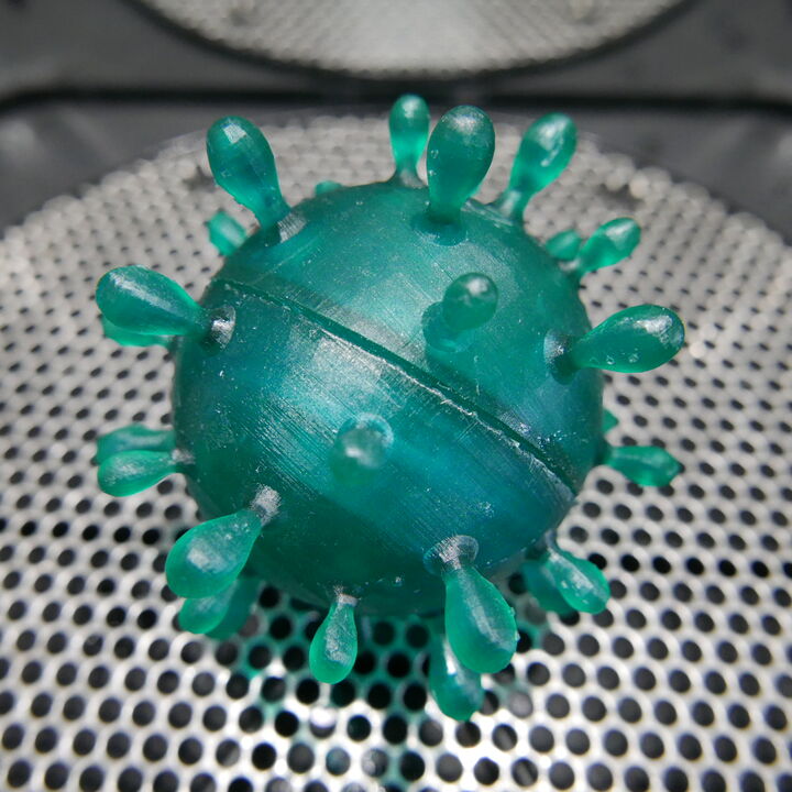
3D printed (SLA) virus located in the first drawer
Puzzle 2 : Covid-19 spreading sequence
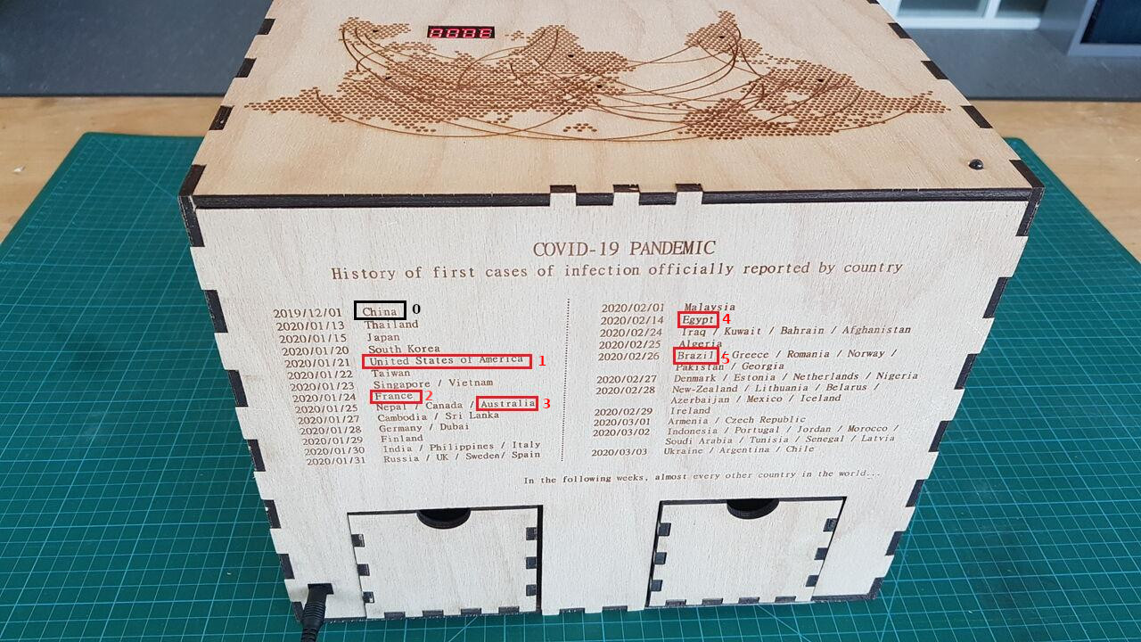
Puzzle 2 - Solution for virus spreading sequence
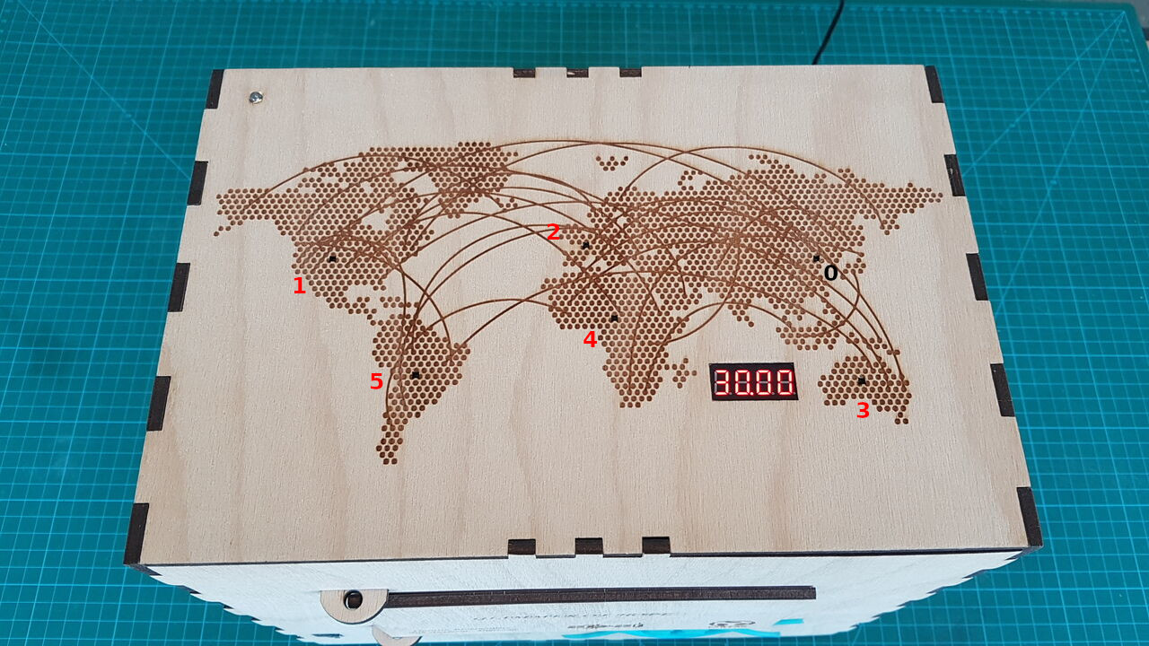
Puzzle 2 - Solution for virus spreading sequence
To solve this puzzle, use the wire hidden in the 3D printed virus previsouly discovered (green one), and connect successively its extremities following this sequence :
- 0-1 (Asia - USA)
- 0-2 (Asia - Europe)
- 0-3 (Asia - Oceania)
- 0-4 (Asia - Africa)
- 0-5 (Asia - South America)
Consequence : Unlocks the right drawer that contains another 3D printed virus (grey one) inside which lies a RFID tag to solve next puzzle.
Puzzle 3 : RFID identification
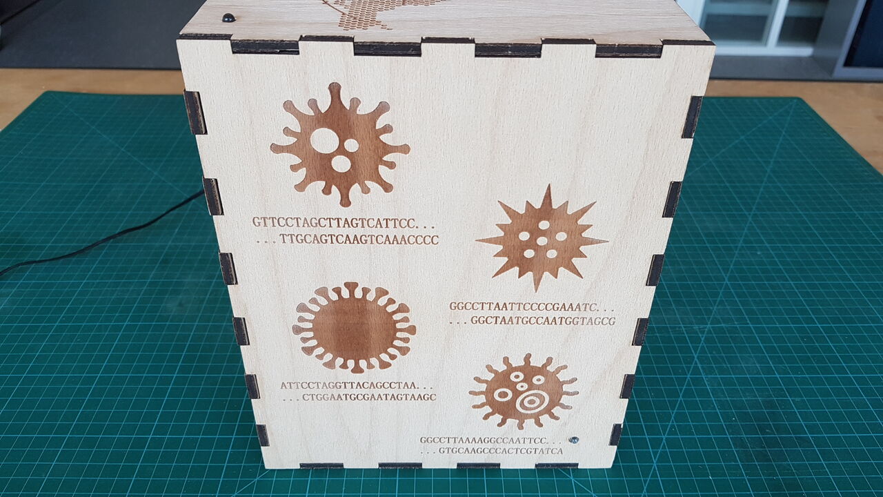
To solve this puzzle, position the RFID tag hidden in the 3D printed virus previously discovered (grey one) on the virus engraved on the box that looks like the 3D printed virus :
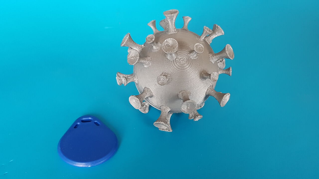
Puzzle 3 - Virus and RFID tag
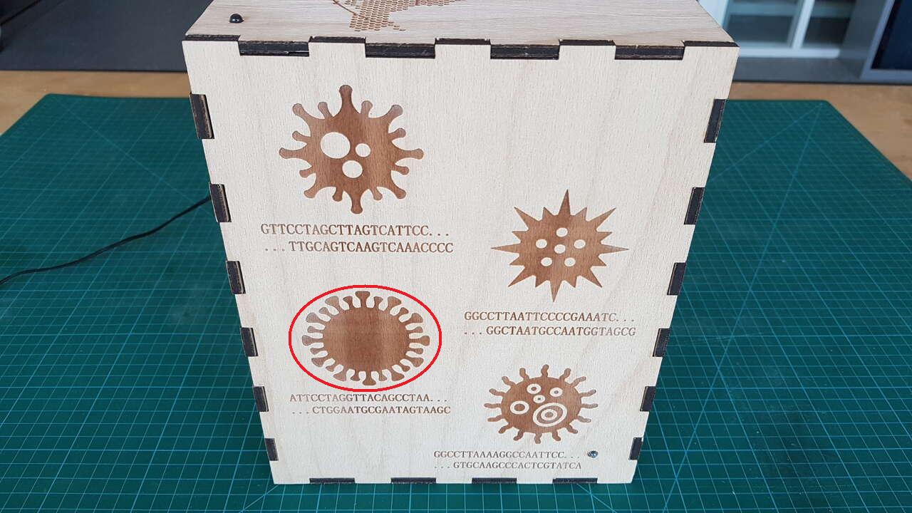
Puzzle 3 - RFID reader location
Consequence : Turns on the LCD and requests players to enter a DNA sequence.
Puzzle 4 : Variants common DNA sequence
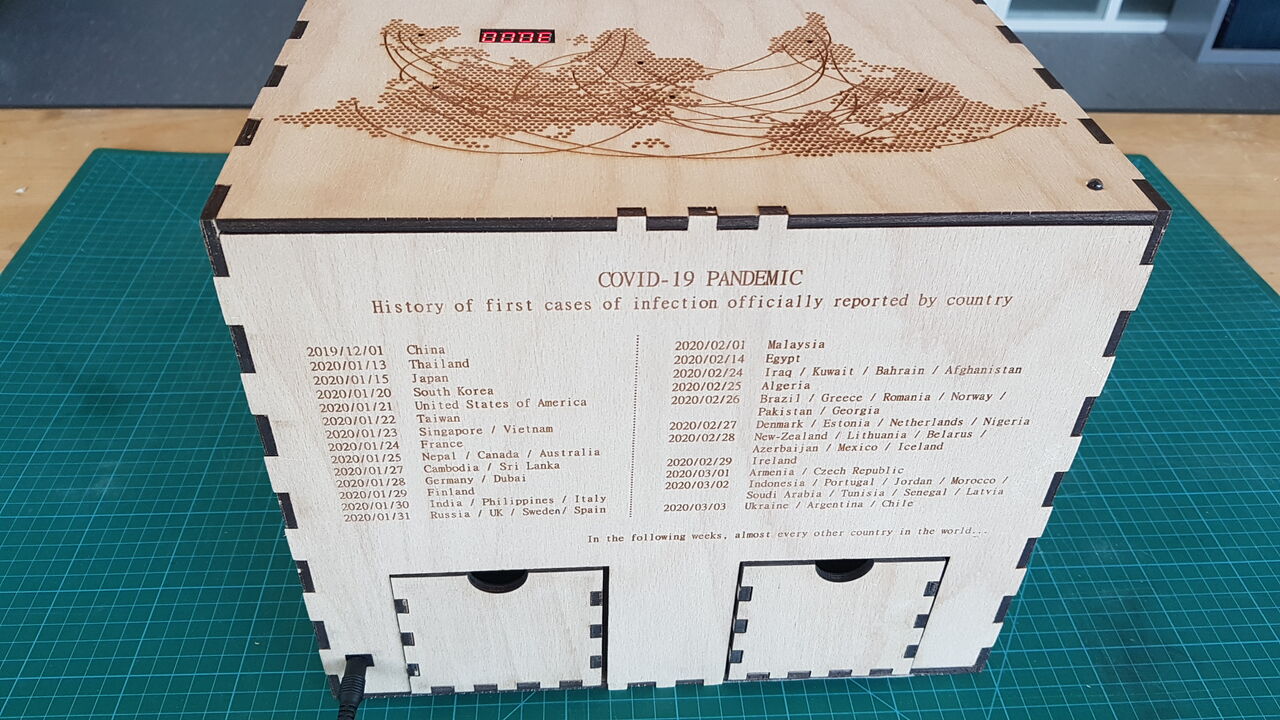
To solve this puzzle, identify which viruses engraved on the puzzle box correspond to the two 3D printed variants found during the game, find the common DNA sequence between those two variants (10 characters), and enter this sequence using the DNA keypad. Note : One of those engraved virus is voluntarily hidden under one of the drawer of the puzzle box.
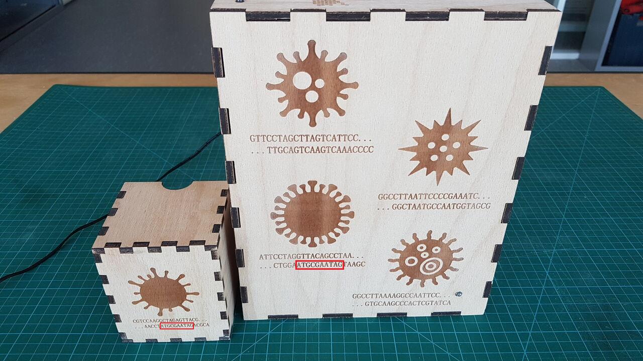
Puzzle 4 - Solution for DNA sequence
Consequence : Unlocks the main door. Game is completed !
Experience feedback
As of 2021/06/16, already 3 groups of friends have had the opportunity to play with my puzzle box. I would like to thank them here (Elise & PE & JM / Ben & Fanny / Raphael).
First of all I am happy to announce that all groups could reach the end of the game without any technical issue, all mechanisms worked as expected even though they sometimes stimulate the box in I different way that I have done myself during my testing activities (ex: once they solve the world map sequence puzzle, they often let the wire connected as they are in a hurry to go to next puzzle).
Results are interesting as all groups basically had the same approach, commited the same mistakes and required a similar time to resolve the game. Initially I thought that people used to this type of games would complete it in around 30 minutes, but I realize that they rather need around 45 minutes. This is positive as it means that the puzzles I created are feasible but non trivial.
Among the main mistakes I observed so far are the following :
- Players think that the first puzzle to be solved implies the DNA keypad as this is the first and only input they can think of. Indeed, they do not imagine that the copper cells can act as capacitive sensors. Although they all touched some cells voluntarily or not, they did not pay attention that the LED blinked blue in response to their touch.
- Two capacitive sensors images are often misinterpreted : Human testing phase is often seen as virus propagation, and the virus image is sometimes interpreted as the first phase (contamination) whereas it is the last one as the virus wears a mask and should thus be interpreted as muted.
- Concerning the world map sequence, they often think that they have to connect several wires to complete the puzzle (which I intentionally orientate them to by placing several wires in the drawer).
- They get stuck at the last puzzle because they do not find the hidden virus engraved below one of the drawer. Indeed when they manage to open drawers with puzzle 1 and puzzle 2, they simply extract the content of the drawers and put them back in their locked position again. And later in the game they do not think that some information can be hidden out there.
Development
I have used a spiral development approach to carry out this project :
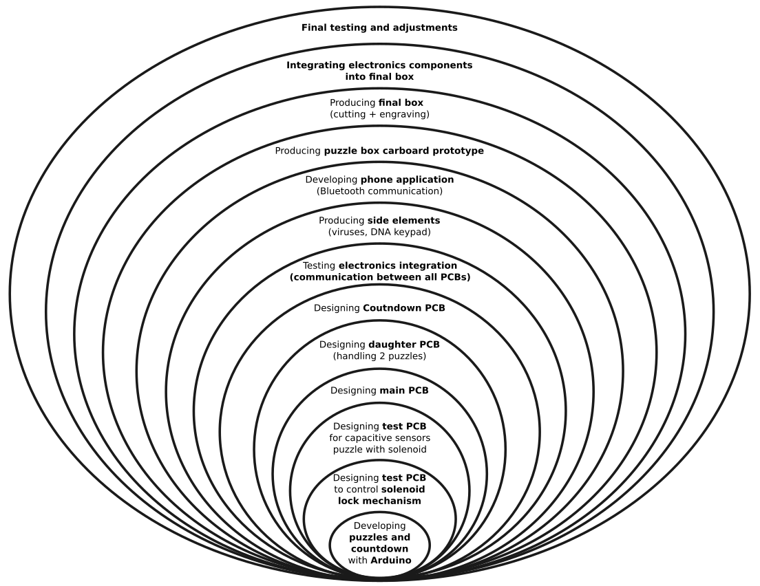
Puzzle box - Spiral development
Electronics and programming
Before presenting in details the different electronics mechanisms I have implemented, let me introduce here the electronics architecture I have chosen for my puzzle box :
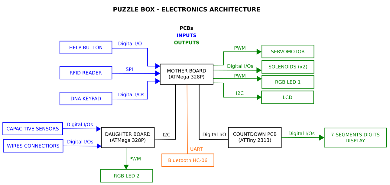
Puzzle box - Electronics architecture
As can be noticed in the above diagram, my puzzle box integrates 3 PCBs. They have been designed in Eagle software, produced by laser cutting and then soldered manually :
- Mother board that controls everything (ATmega328P microcontroller).
- Daughter board that handles puzzle 1 and puzzle 2 (ATmega328P microcontroller).
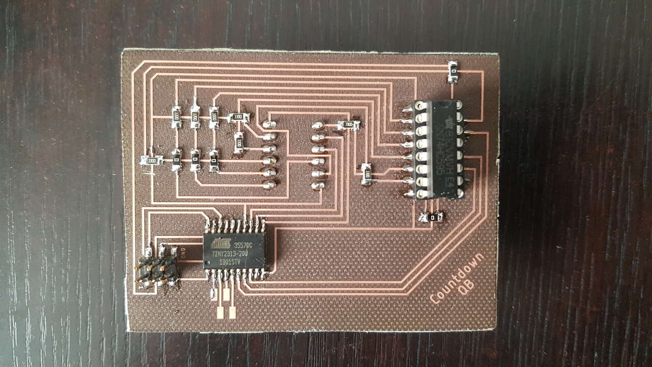
- Side board to handle countdown function (ATTiny2313 microcontroller).
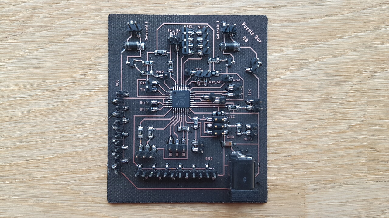
Puzzle box - Mother board
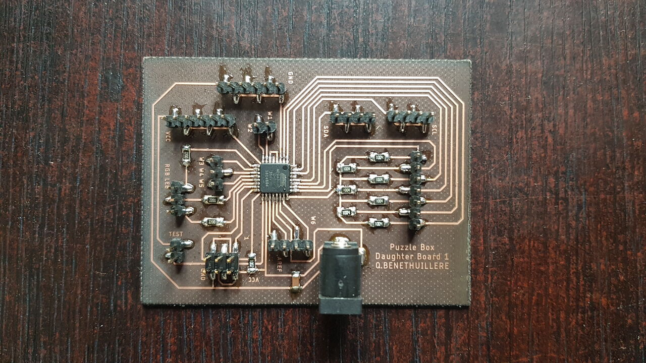
Puzzle box - Daughter board
 |
 |
| Countdown PCB - front view | Countdown PCB - back view |
Solenoid lock mechanism
In this section I present an overview of the tests I performed to control my solenoid lock mechanisms.
The first test I perfomed was to control a 12V solenoid with a Arduino Uno board as this could definitely be an option for the lock mechanisms I wanted to implement in my puzzle box.
Fritzing sketch of the electronic assembly :
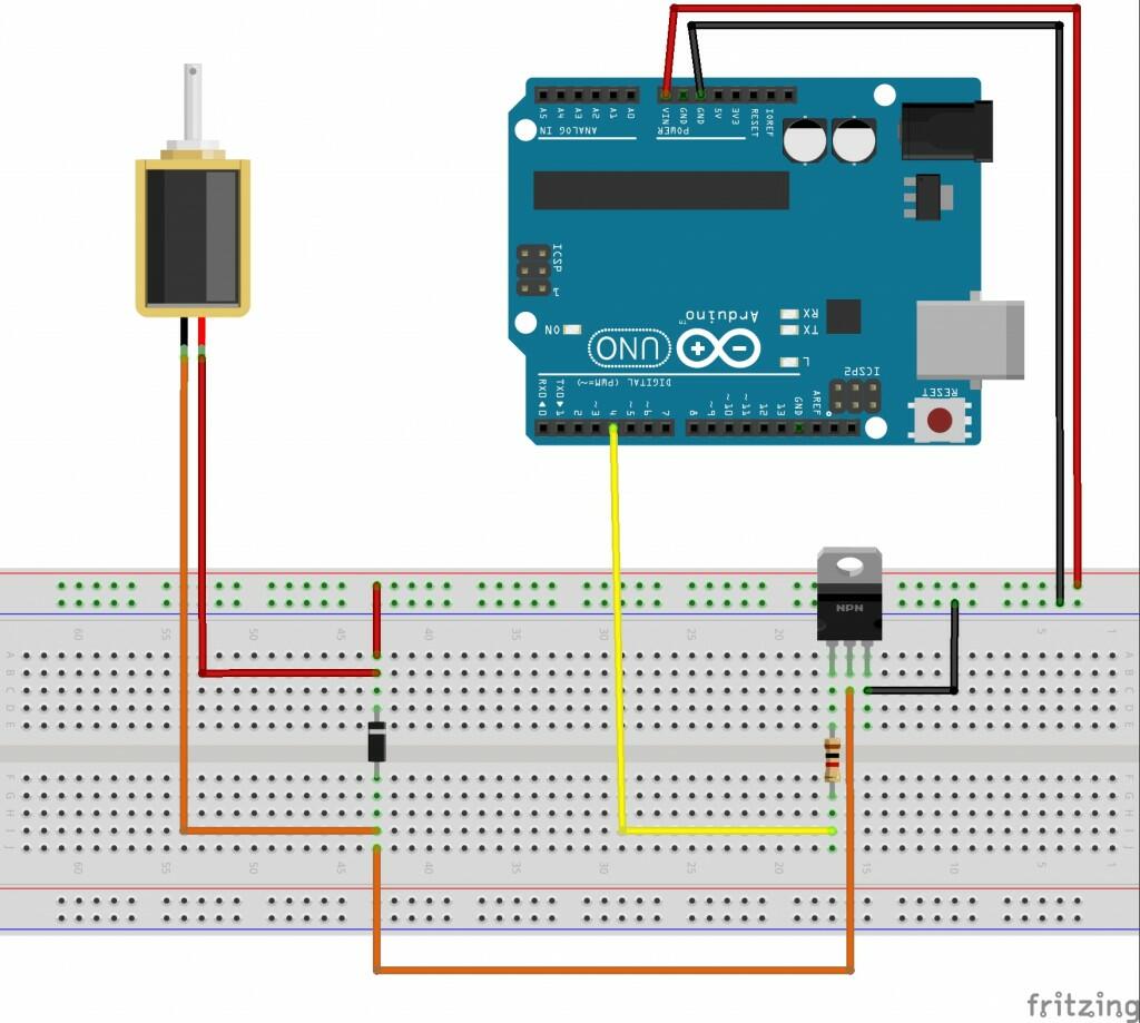
12V solenoid lock mechanism - Fritzing skecth
Material :
- Arduino Uno (x1)
- Breadboard (x1)
- 12V solenoid (485-1512) (x1)
- 1kΩ resistor (x1)
- Diode (1N4007) (x1)
- MOSFET (IRF740) (x1)
Important : This system has to be powered with 12V (and at least 800 mA) through the jack socket because of the 12V solenoid used.
Later in the course, during the electronic design week and the embedded programming week I had the opportunity to test a solenoid lock mechanism that works with 5V. As explained in the pages mentioned just before, I was able to control the opening of the solenoid lock mechanism based on user interaction with a push button. As a reminder, the delay with the lock mechanism open implemented after a push button press is to let some time for the user to open the previously locked compartment, and the inactivation delay that follows is simply to protect the lock mechanism solenoid from overheating. This behaviour is close to the one I have implemented in my final project.
Countdown
In this section I present the countdown system that I have implemented. This coutdown is used to let the players know how long they have left to complete their mission.
As always I have started to develop this mechanism with Arduino environment.
Fritzing sketch of the electronic assembly :
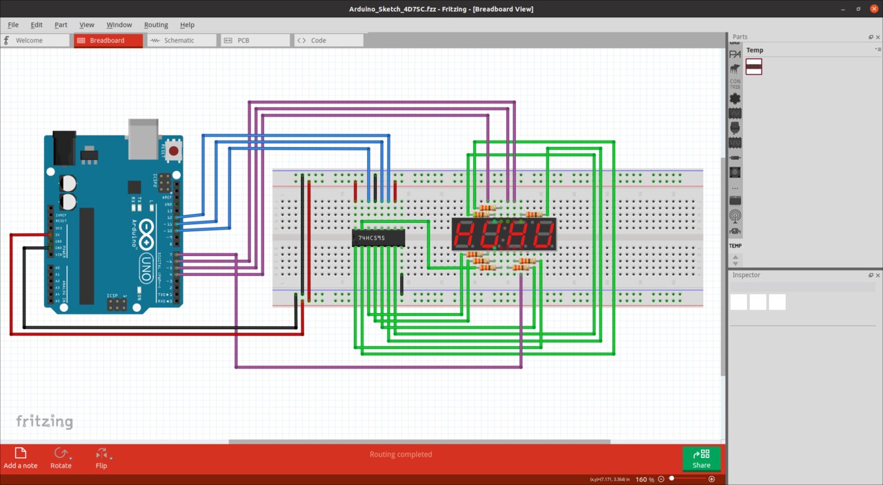
Countdown mechanism - Fritzing skecth
Material :
- Arduino Uno (x1)
- Breadboard (x1)
- 8 bits shift register (74HC595) (x1)
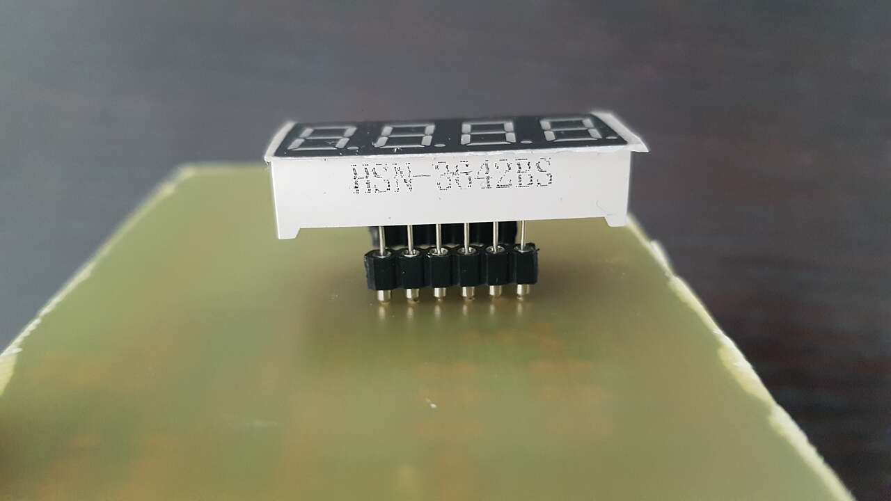
- 4 digits 7 segments display (HSN-3642BS) (x1)
- 330Ω resistors (x8)
During the Output devices week I could replicate this countdown system on a proper PCB. Please refer to that week’s page for further information on this activity. Just a quick video here to present the final functionality :
Access control - keypad
In this section I present the development phases I conducted to obtain an access control using push buttons and an LCD as feedback. The access code corresponds to a DNA sequence.
As usual, I started by testing a first version of my access control using Arduino environment.
This is a great opportunity to demonstrate the necessity of debouncing push buttons for certain applications, such as counters. In this example below, for demonstration purpose only, the first button has NOT been debounced, whereas second button has been debounced. Note: Obviously, all buttons have been debounced in the access code program presented above.
Fritzing sketch of the electronic assembly :
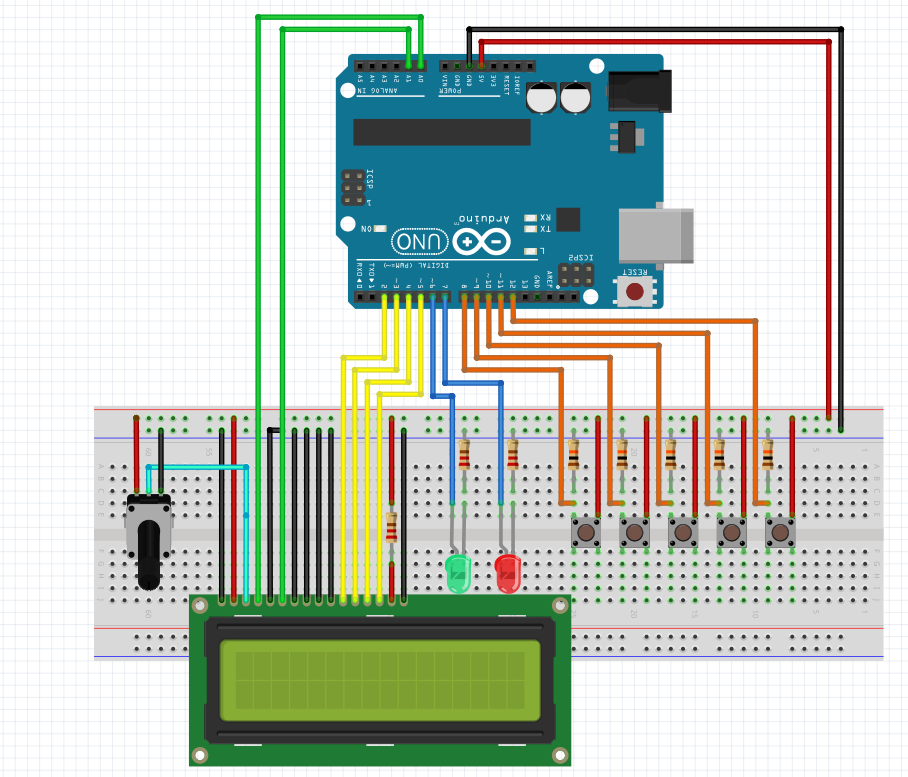
Access code - Fritzing skecth
Material :
- Arduino Uno (x1)
- Breadboard (x1)
- Jumper wires
- LCD (16 columns, 2 rows) (x1)
- Potentiometer 10 kΩ (x1)
- LED green (x1)
- LED red (x1)
- Push buttons (x5)
- 220Ω resistors (x3)
- 10kΩ resistors (x5)
Later on, during the Molding and casting week, I designed and produced a custom DNA keypad. Please refer to this week’s page for further information on this activity. I just present here the final result I obtained for this DNA sequence access control mechanism.
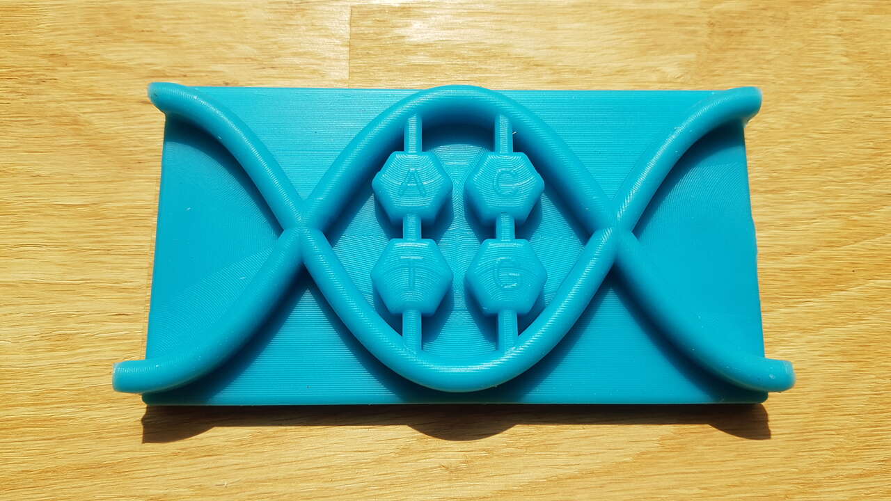
Keypad front side
 |
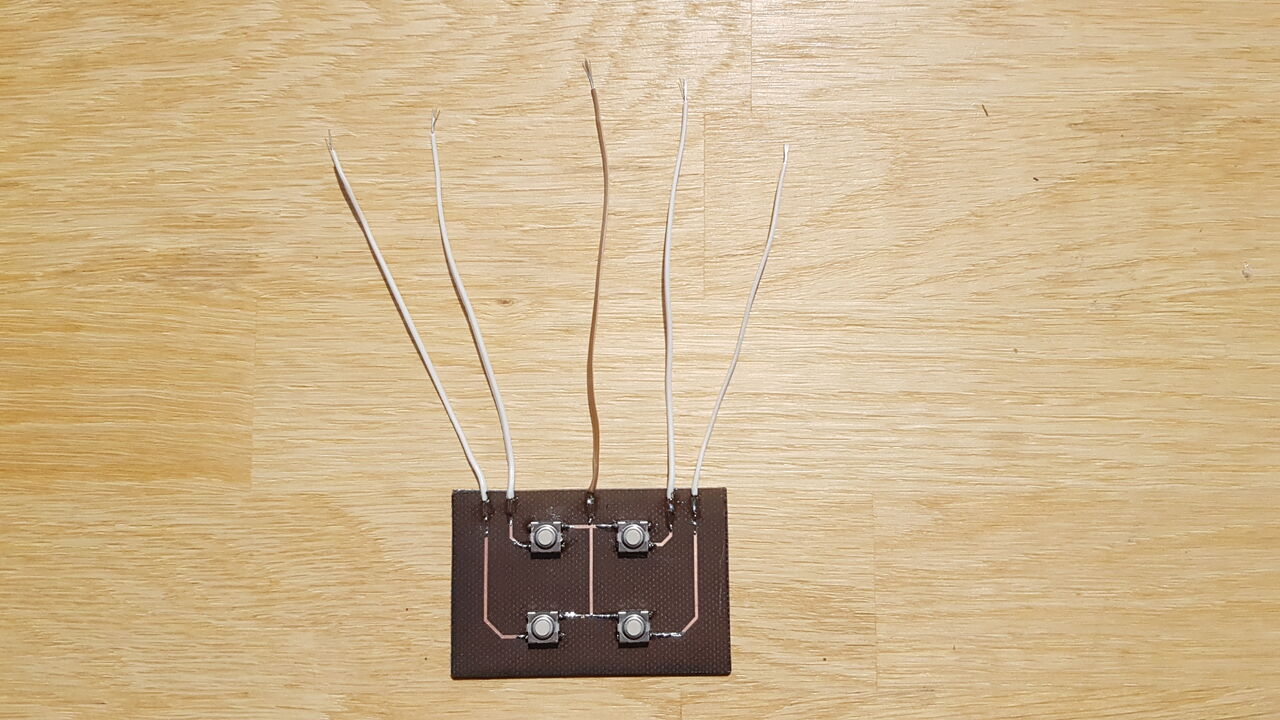 |
| Keypad back side | PCB buttons integrated at the back of the DNA keypad |
Access control - RFID
In this section I present the development phases I conducted to obtain an access control using RFID modules.
Many websites present the RFID technology, and a lot of makers use them for their Arduino projects. To get started I have mainly been through this RFID tutorial (in french), and this RFID tutorial (in english). Also I have read the Arduino MFRC522 Library documentation, which was really useful to me.
RFID (Radio Frequency IDentification) system consists of two main components :
- a transponder usually in the form of a card or tag.
- a transceiver also known as interrogator/reader.
The RFID reader consists of a Radio Frequency module and an antenna which generates high frequency electromagnetic field. On the other hand, the tag is usually a passive device, meaning that it doesn’t contain any power supply. Instead it contains a microchip that stores and processes information, and an antenna to receive and transmit a signal. To read the information encoded on a tag, it must be placed in close proximity to the RFID reader (within few centemeters). The reader generates an electromagnetic field which causes electrons to move through the tag’s antenna and subsequently powers the tag’s chip. Once powered, the tag’s chip responds by sending its stored information back to the reader in the form of another radio signal. This so called backscatter, is detected and interpreted by the reader which then sends the data out to a computer or a microcontroller.
As usual, I started by testing a first version of my access control using Arduino environment. I decided to make the RFID module and the Arduino exchange data using the SPI protocol (Serial Peripheral Interface).
Fritzing sketch of the electronic assembly :
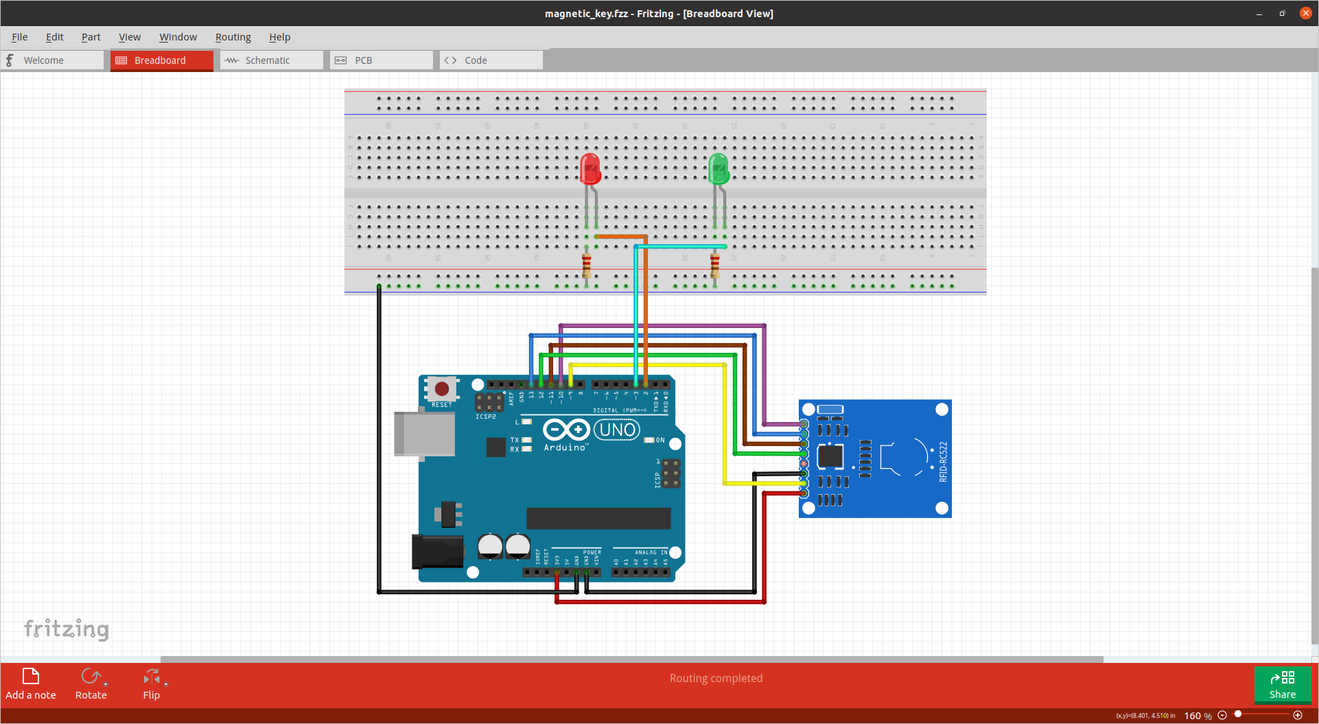
RFID access control - Fritzing skecth
Material :
- Arduino Uno (x1)
- Breadboard (x1)
- Jumper wires
- LED green (x1)
- LED red (x1)
- 220Ω resistors (x2)
- RFID MFRC522 13.56MHz (x1)
- RFID tags/cards (as many as you want)
Following this first test, I noticed that all cards could be read by the RFID reader, however only one tag out of five could be read. After some searches on the internet I realized that many persons already observed a similar behaviour due to poor quality of cheap RFID readers copies, such as the ones I may have bought. One of the solution suggested was to power the RFID readers with 5V instead of 3.3V, which I tried and it worked perfectly fine for me. I know that this solution is definitely not ideal but as in my application the RFID readers will only be powered for a relatively short amount of time, I consider that they will not get damaged.
Once that I had managed to work with one RFID reader, I could extend my tests to using 2 RFID readers in parallel which corresponds to the situation I would have liked for my final puzzle box.
As can be seen in the video, the behaviour is the following :
- Only one tag is authorized per RFID reader.
- If both tags are presented within a close interval of time to their corresponding RFID readers, the green LED turns ON, access is authorized.
- If a tag is presented to a RFID reader for which it is not authorized, the red LED turns ON, access is denied.
- If only one tag is presented to its corresponding RFID reader, the yellow LED turns ON, access is denied but it indicates to the user that this tag corresponds to this RFID reader.
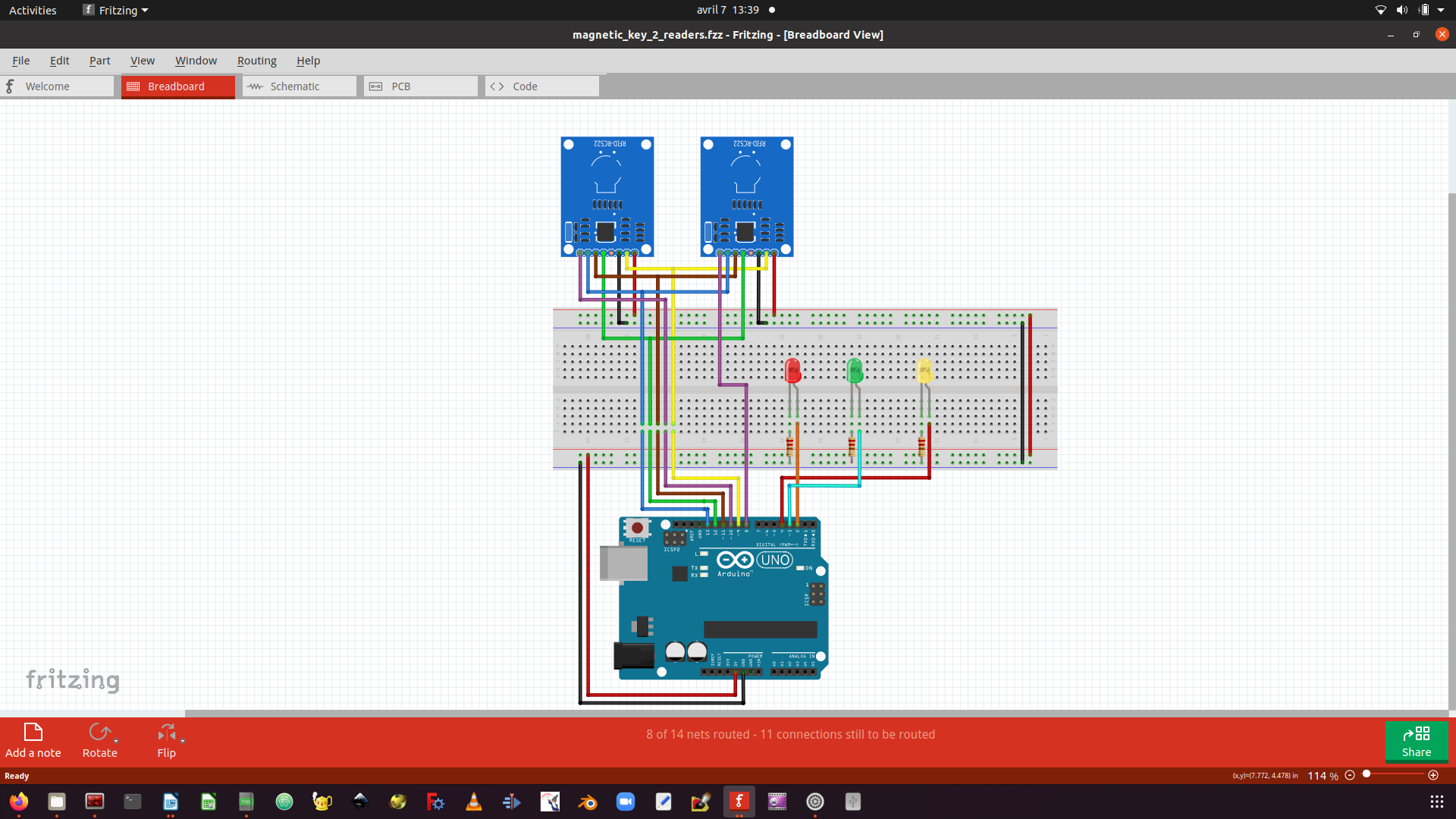
RFID access control with 2 readers - Fritzing skecth
Material :
- Arduino Uno (x1)
- Breadboard (x1)
- Jumper wires
- LED green (x1)
- LED red (x1)
- LED yellow (x1)
- 220Ω resistors (x3)
- RFID MFRC522 13.56MHz (x2)
- RFID tags/cards (as many as you want)
Note: At this stage I was facing an issue that I did not understand. Indeed, I needed to power ON/OFF several times my Arduino Uno so that both RFID readers would work simultaneously. I would have liked to investigate more on this issue but unfortunately I did not find time for it during this FabAcademy program. As the same problem occured when I tested my software on the main PCB that I designed during the Networking and Commuication week, I decided to rather use only one RFID reader for my puzzle box.
Capacitive sensors wall
During the Input devices week I designed a PCB to test a puzzle based on capacitive sensors. The idea is to touch each sensor in a particular order to unlock the mechanism.
As always, I started by testing this functionality with Arduino.
Fritzing sketch of the electronic assembly :
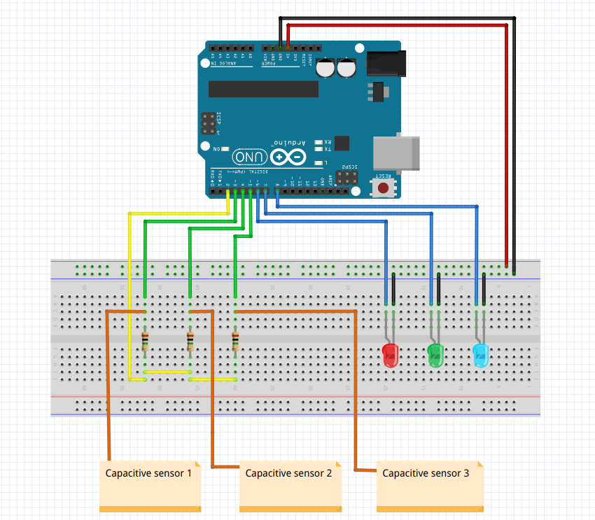
Capacitive sensors - Fritzing skecth
Material :
- Arduino Uno (x1)
- Breadboard (x1)
- Jumper wires
- LED green (x1)
- LED red (x1)
- LED blue (x1)
- 220Ω resistors (x3)
- 1MΩ resistors (x3)
- Copper sheet squares (x3)
I could then go on by designing the same circuit on a proper PCB, and replacing copper sheet squares by a nice copper plate I engraved with the laser cutter.
Later on I could make a new version of this copper plate for final integration in the puzzle box. The whole point was to hide soldering from players so that they do not easily understand that touching those sensors can actually do something.
World map wire connections
I really wanted to engrave a world map on my puzzle box, especially to demonstrate the world interconnections and how all this led to an extremely fast propagation of the Covid 19. Thus I imagined a puzzle that requires user to connect what is known as the starting point of the pandemic (Asia) to the other areas of the world in a particular order based on first Covid19 cases officially reported.
Following my habits, I started with an Arduino program, which is very similar to the one I created for the capacitive sensors wall. Also I took this opportunity to replace red / green / blue LEDs by a single RGB LED.
Fritzing sketch of the electronic assembly :
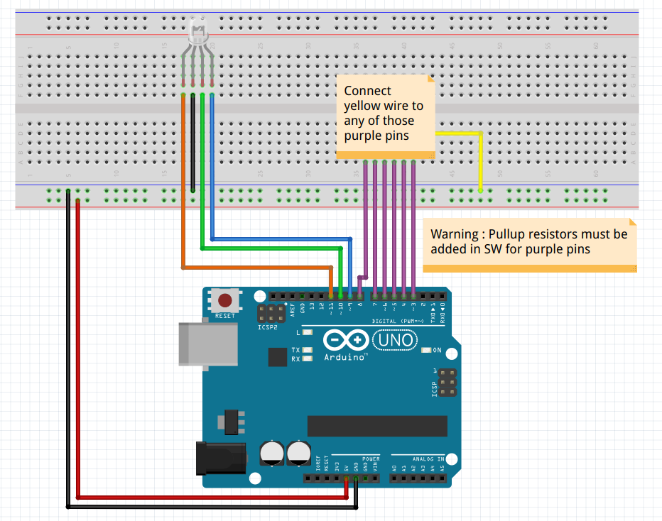
World map wire connections - Fritzing skecth
Material :
- Arduino Uno (x1)
- Breadboard (x1)
- Jumper wires
- RGB LED (x1)
- 220Ω resistors (x3)
Around week 14 I was able to design and produce a PCB that handles both the capacitive sensors puzzle and the world map sequence puzzle. This PCB is presented in the beginning of the Electronics section under the name “Daughter board”.
Phone application
During the Interface and Programming week I have developed a phone application with MIT App Inventor that allows me to interact with the different mechanisms of my puzzle box (solenoid lock mechanisms, servomotor, LED, LCD, and countdown). It especially allows me to send custom messages to players while they are progressing through the game, to pause/resume the countdown if needed, and to open the lock mechanisms. This is particularly useful to make sure that all mechanisms are working properly before people start playing. For further information on the development of this application, please refer to the dedicated week’s page.
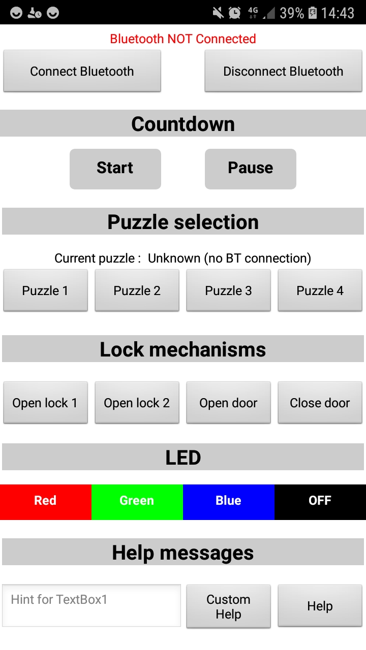
Puzzle box application - MIT App Inventor
Electronics integration
On several occasions, while I was progressing in the electronics development of my mechanisms, I took time to integrate all the electronics systems/components ready to make sure that the entire system was working as expected. The video below corresponds to the final electronics integration test I have performed before starting to design the puzzle box frame :
Design
Here are the parts that I have designed for my puzzle box :
- The box itself (including drawers and all the interior pannels to hide electronic components and wires).
- Several 3D printed supports to hold electronics components inside the box.
- Two 3D printed screwable viruses that will contain elements to progress in the game (RFID tag, and electronic wire).
- DNA keypad and associated mold for the digicode access control.
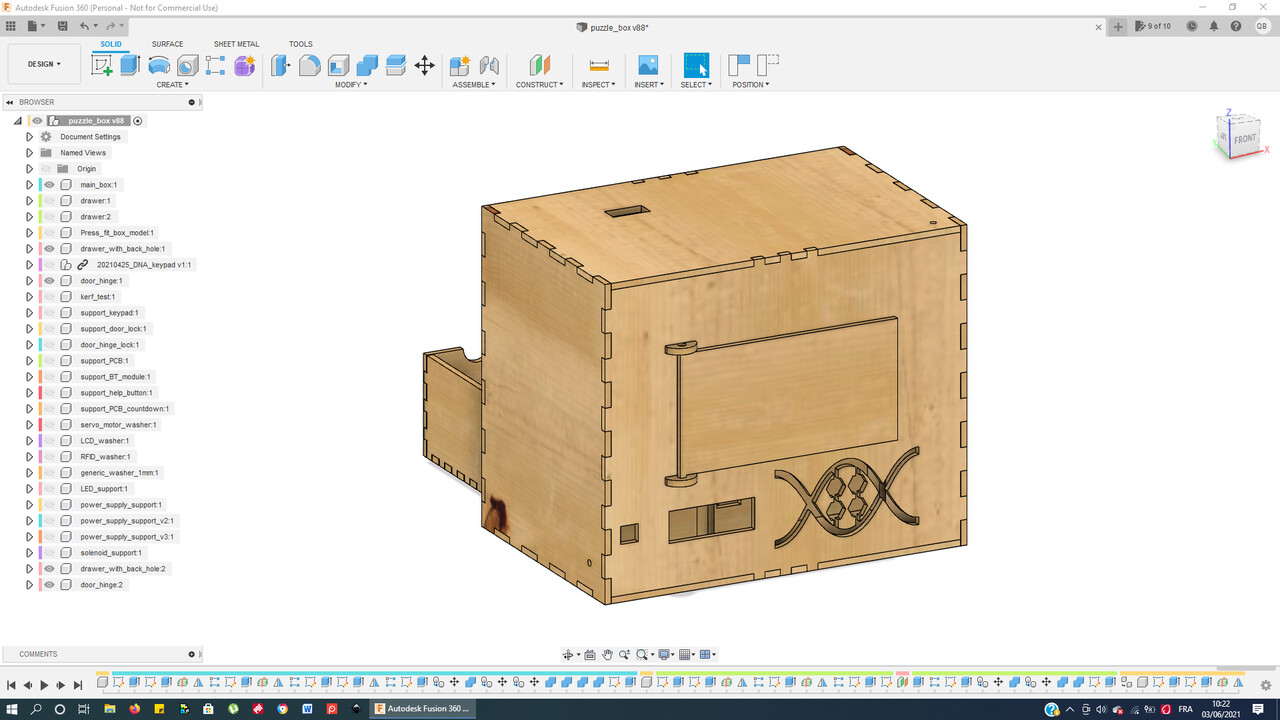 |
 |
| Puzzle Box - Front view - Fusion 360 | Puzzle Box - Back view - Fusion 360 |
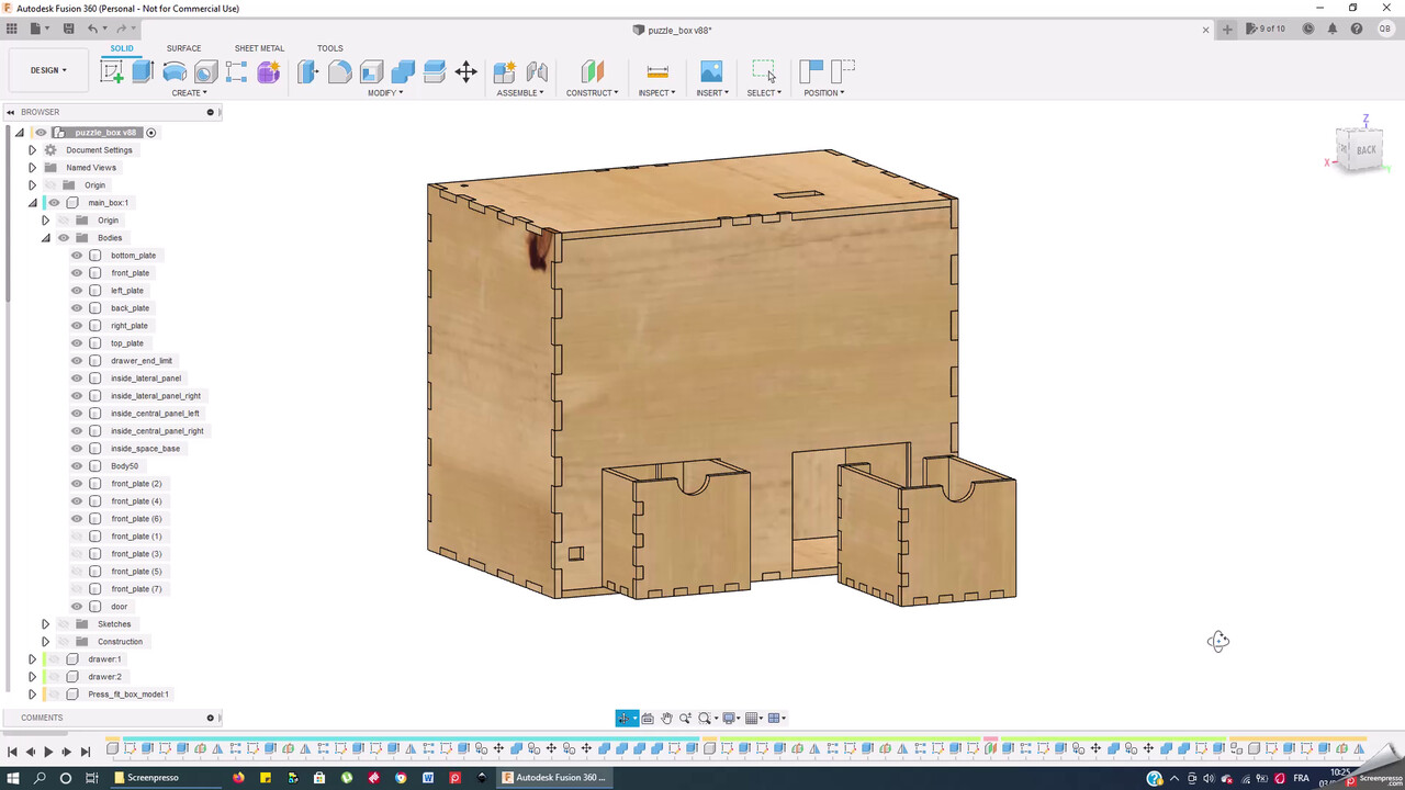
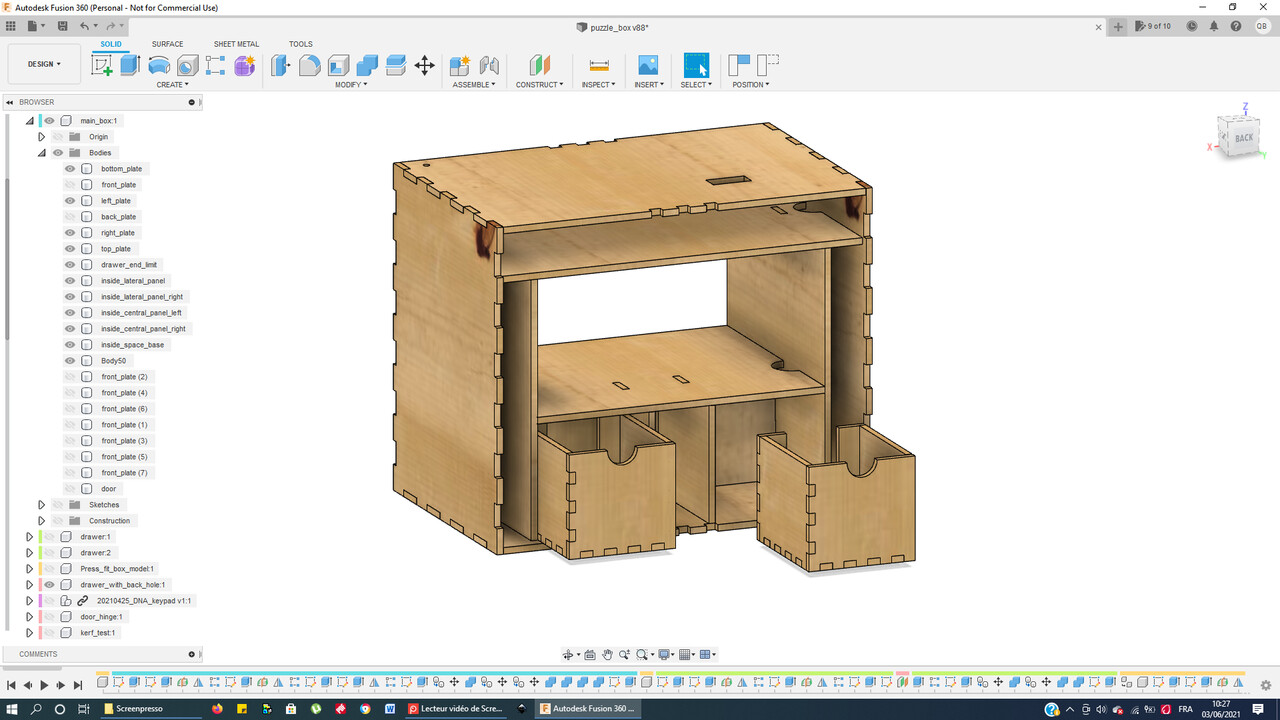 |
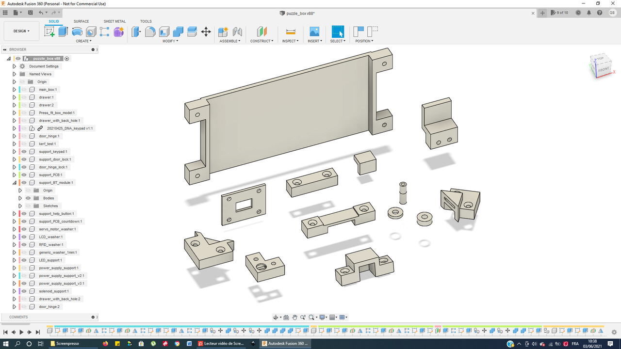 |
| Puzzle Box - Inside view - Fusion 360 | Puzzle Box - Electronics supports - Fusion 360 |
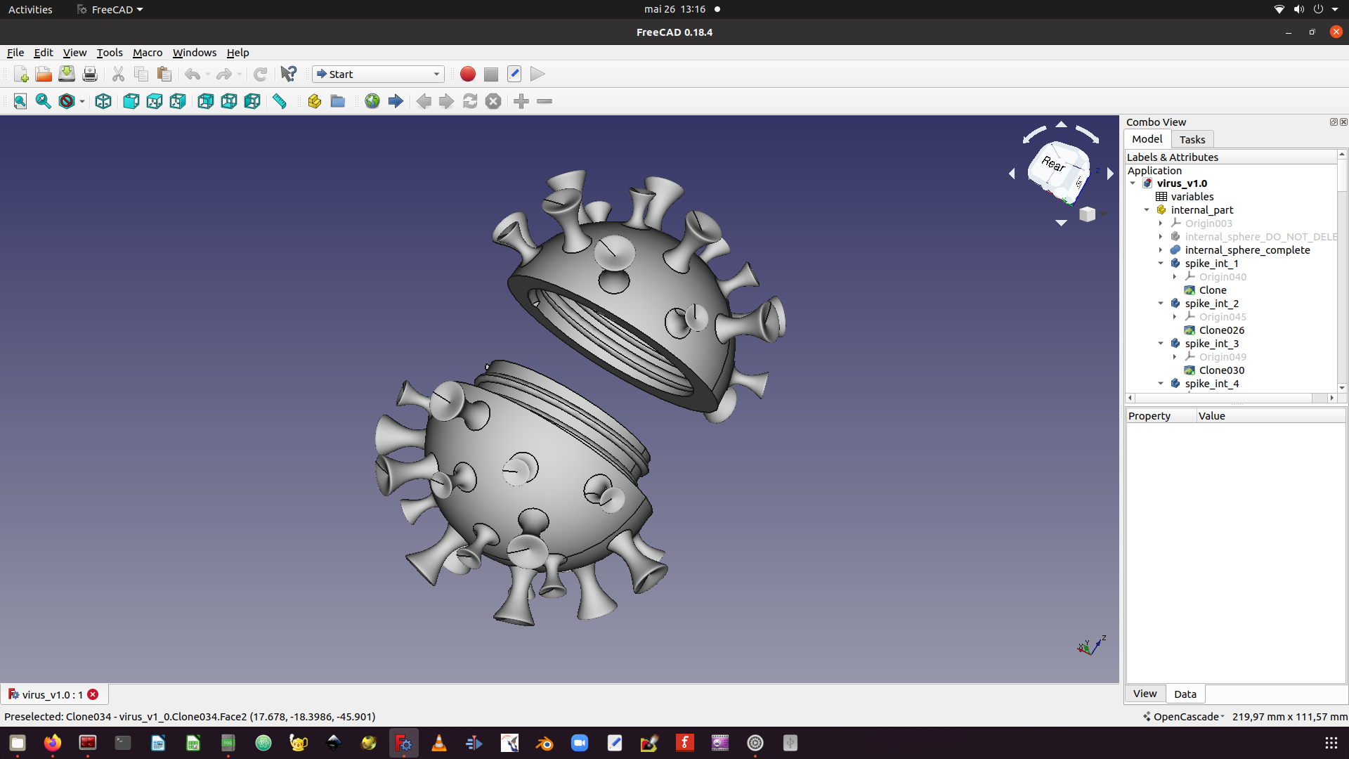 |
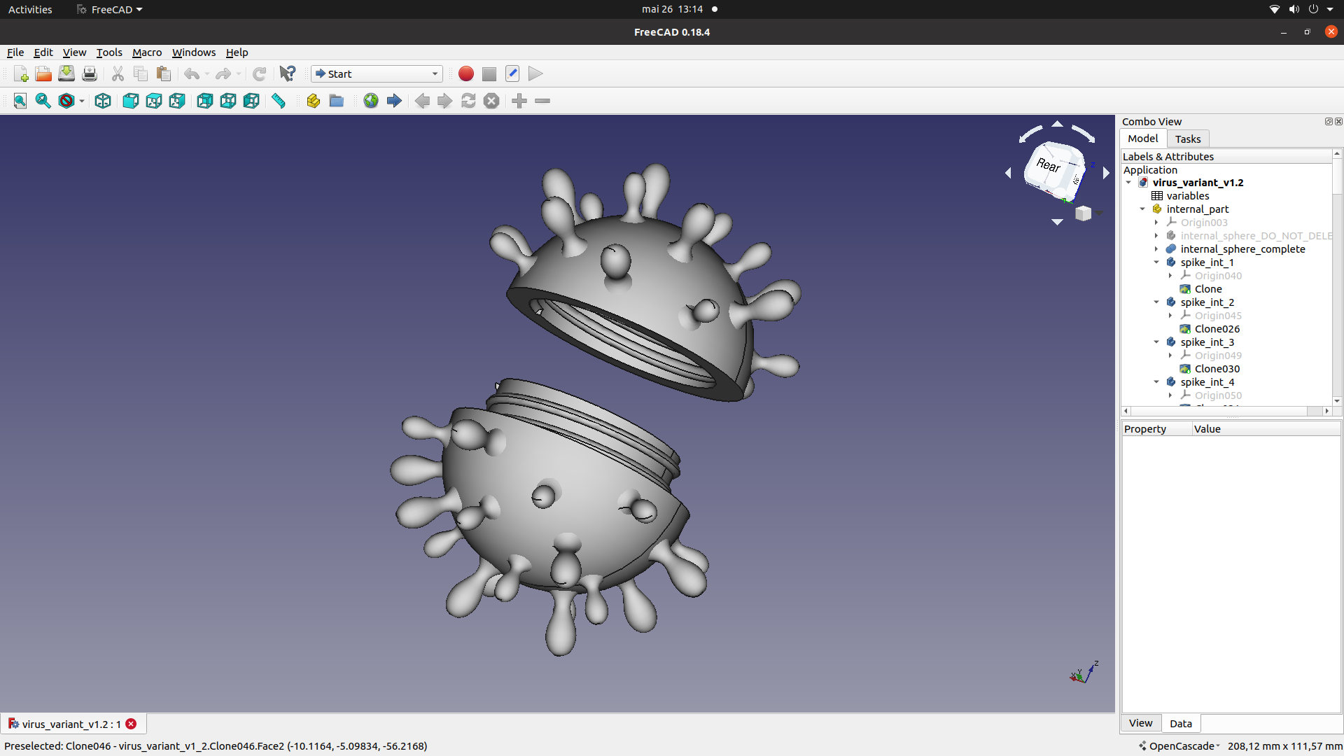 |
| Virus model - FreeCAD | Virus variant model - FreeCAD |
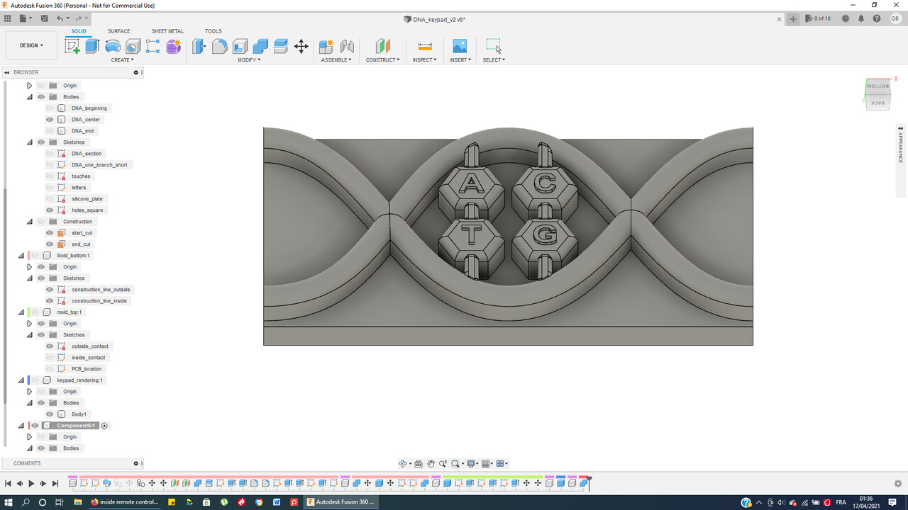 |
 |
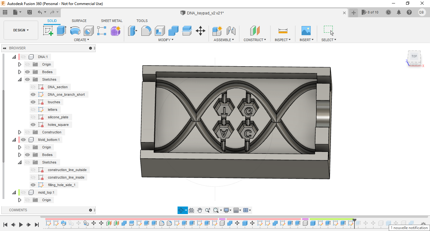
| DNA keypad - front view - Fusion 360 | DNA keypad - back view - Fusion 360 |
 |
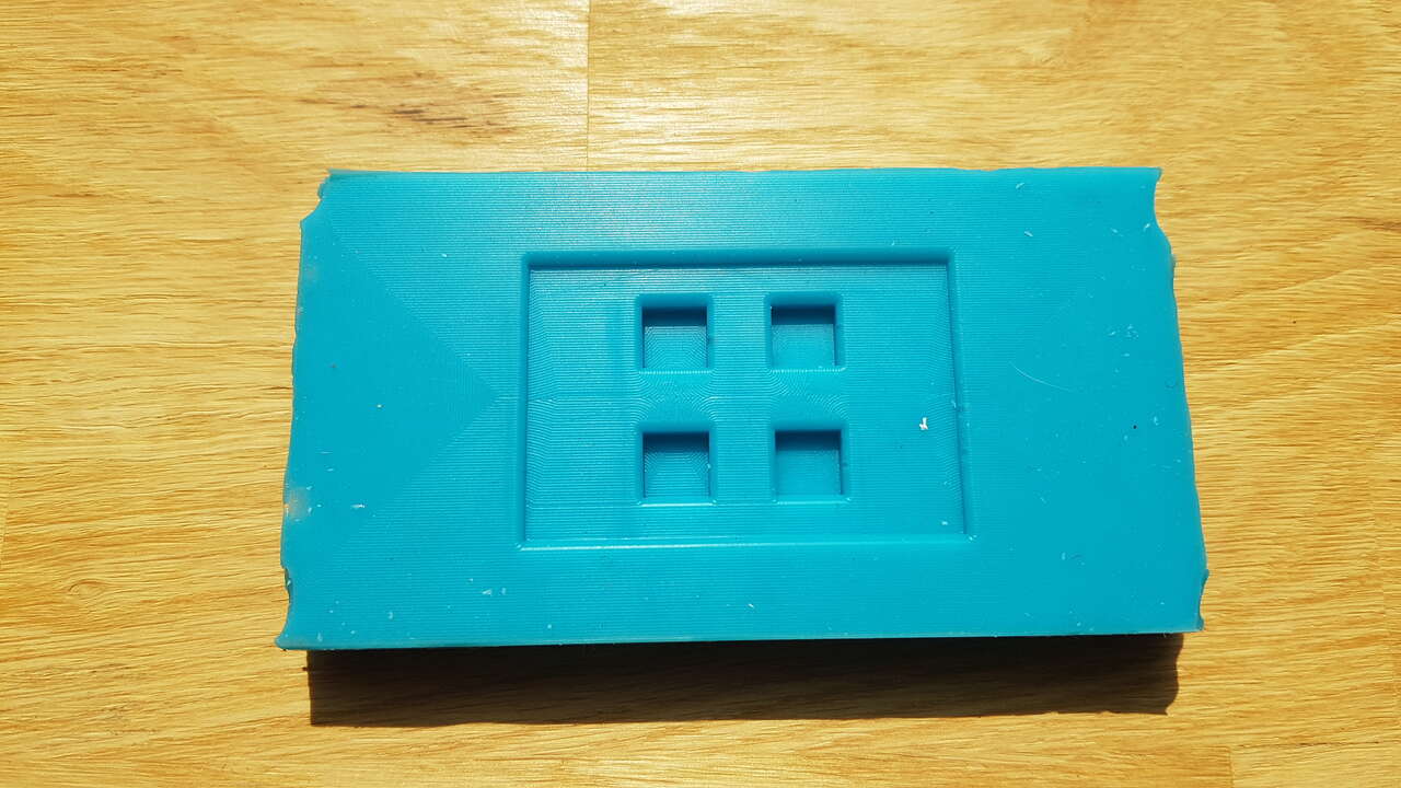
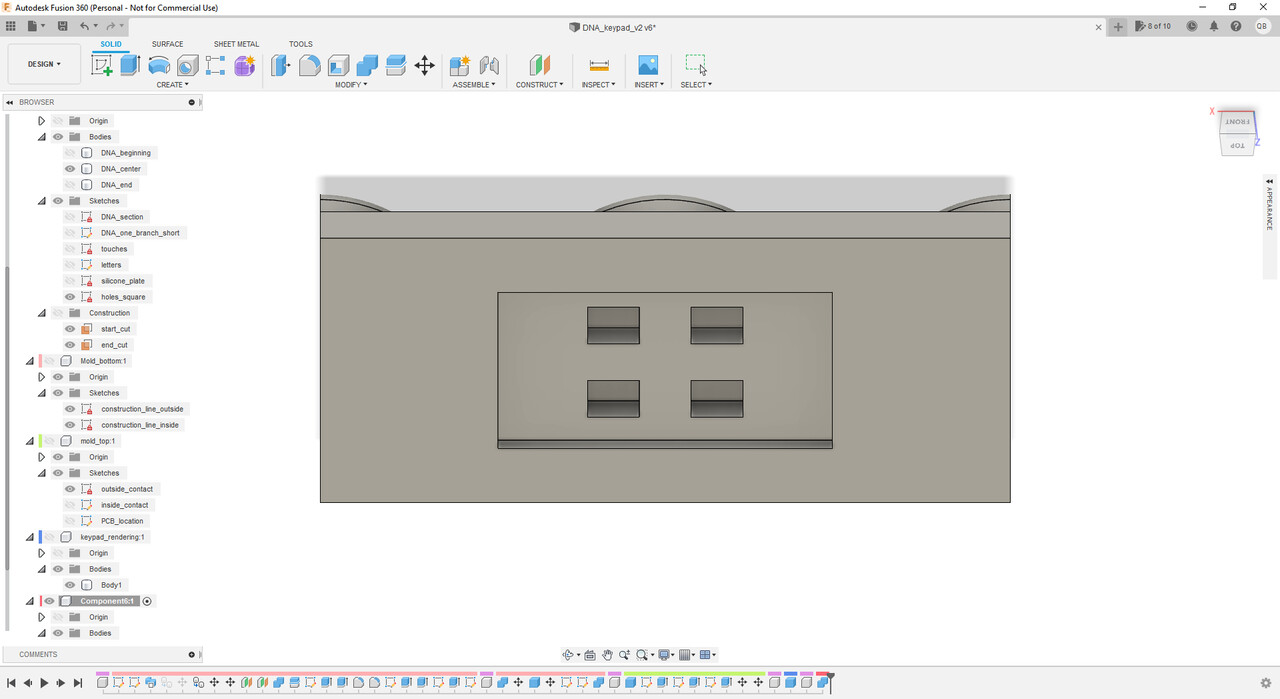
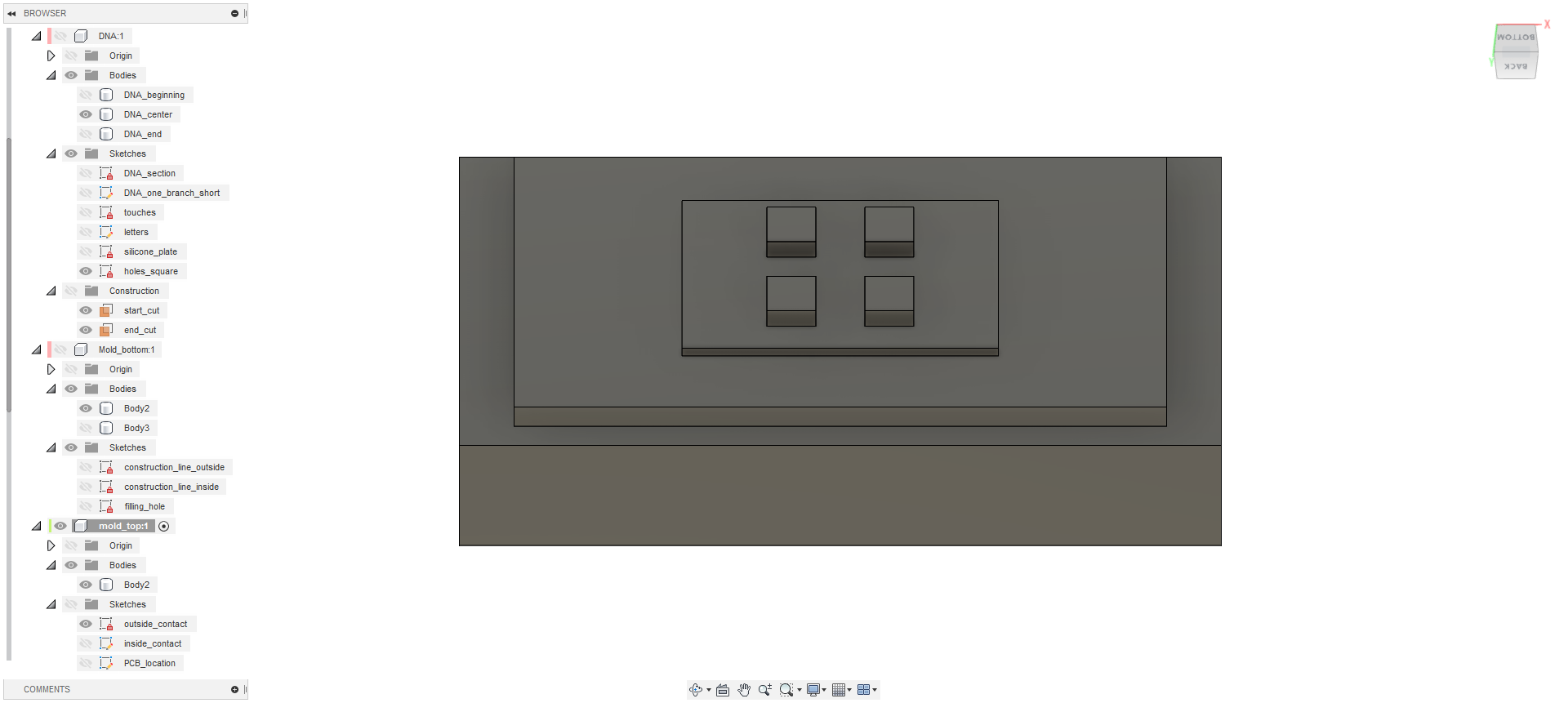 |
| Keypad mold bottom part - Fusion 360 | Keypad mold top part - Fusion 360 |
Note :
Production
3D printed virus
As can be seen on the screenshots above, and the video below, the two 3D printed virus consist of 2 half spheres that can be screwed one into the other.
I have designed this virus model using FreeCAD software. I made a parametric design which allowed me to easily adjust all dimensions and also the shape of the virus spikes (pretty convenient to generate variant viruses). As 3D printing is a pretty long process, before printing the complete model I had to make sure that the thread I designed was working fine. After a first test (white filament) with not enough margin in my thread design, I performed little adjustments (applied a diameter clearance of 0.4 mm on the cylinder parts) that permitted me to obtain the successful result (grey filament) presented in the video hereunder :
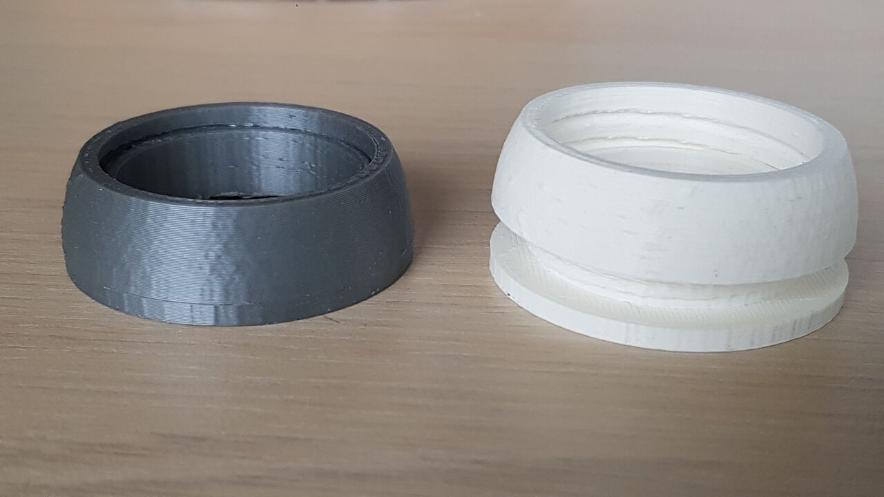
3D printed thread tests
Based on previous observation, I printed my final model using a clearance of 0.54mm (diameter) between half sphere internal and external parts, which gave a perfect result when coming to fit those parts together.
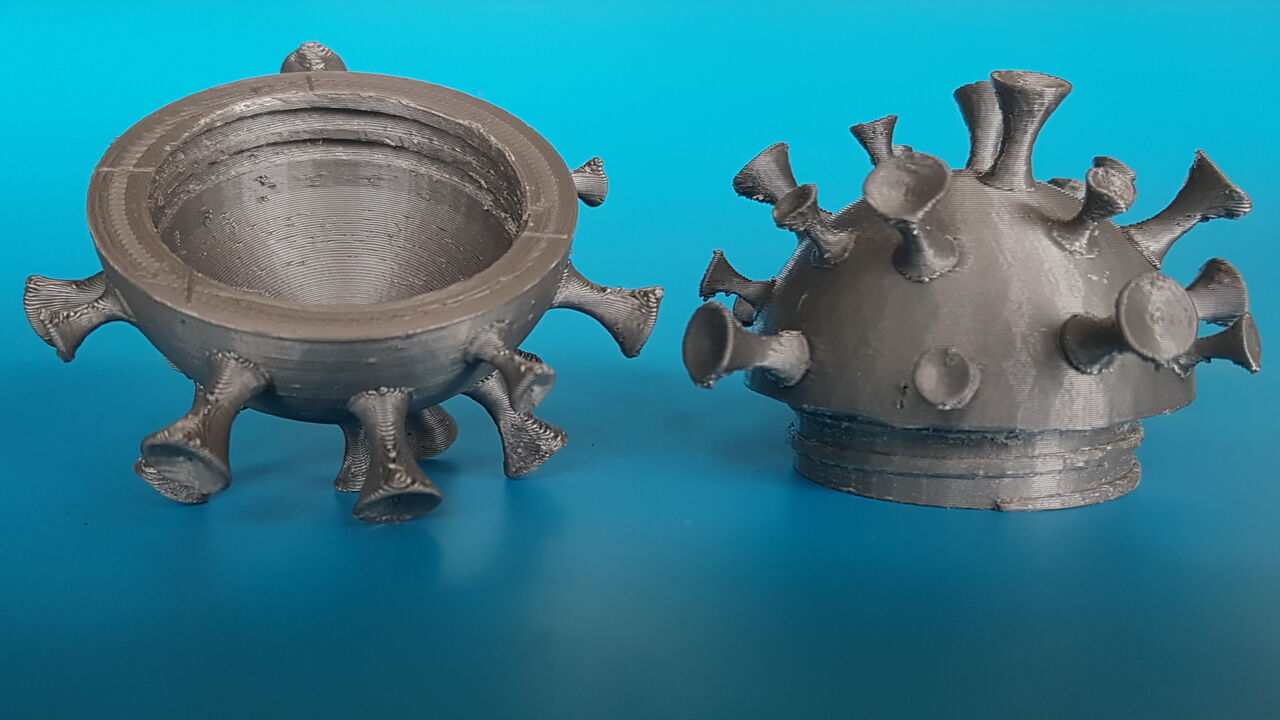 |
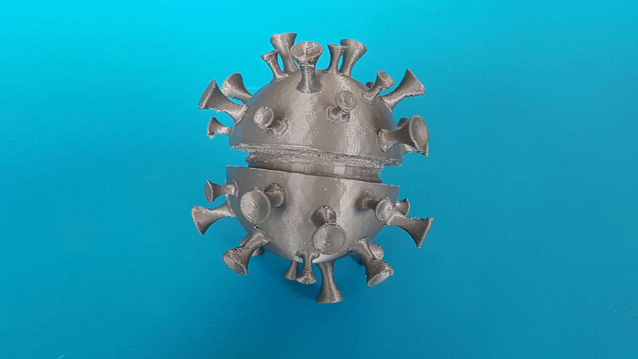 |
| Half spheres | Half spheres being assembled |
Herebelow a video extract of the virus printing (FDM) :
As for the variant virus I decided to use SLA 3D printing (more information on this process can be found in the Wild card week).
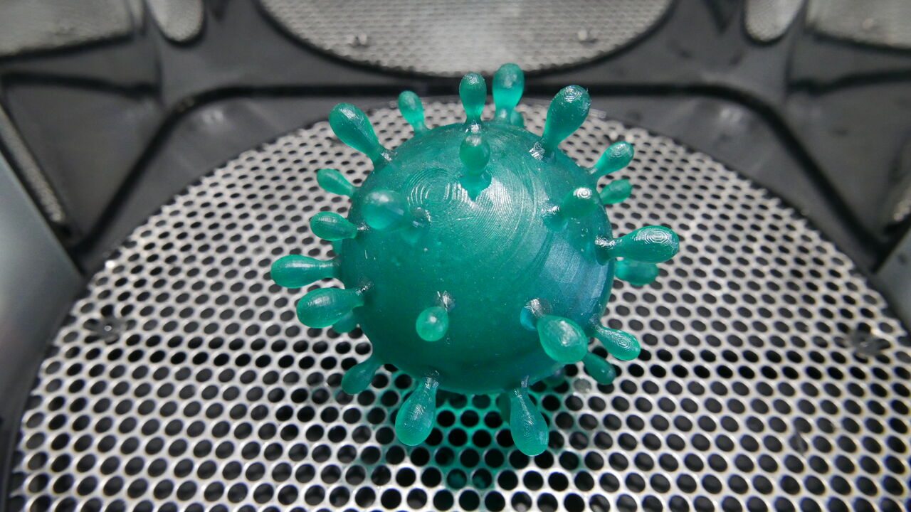
Virus variant (SLA printing)
Box
The laser laser cutter has been used to cut and engrave all faces of the puzzle box. A few videos present those processes :
Settings for cutting :
- Speed : 15%
- Power : 100%
- Frequency : 100%
- Repetition(s) : 3 repetitions at standard height / 3 repetitions at height +1.5mm / 2 or 3 repetitions at height +4.0mm
Settings for engraving :
- Speed : 60%
- Power : 80%
- Frequency : 50%
- Repetition(s) : 1
Here below are presented all the parts laser cutted :
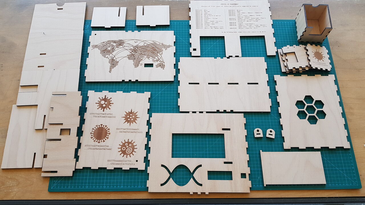
Puzzle box - All parts - Laser cutter
Integration
Then a bunch of parts have been 3D printed in order to fit all the electronics components along the different faces of the puzzle box. No screw is visible to the end user as they have all been fixed from the inside of the box.
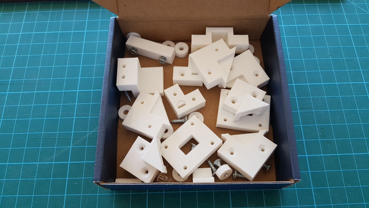
Puzzle box - 3D printed supports
Integrating all the electronics components inside my puzzle box and distribute them on all the faces of the box was quite a challenge because of the considerable numbers of cables. As can be seen on the picture below the number of wires to connect all electronics modules together is non neglectable (and one puzzle is missing in the picture).
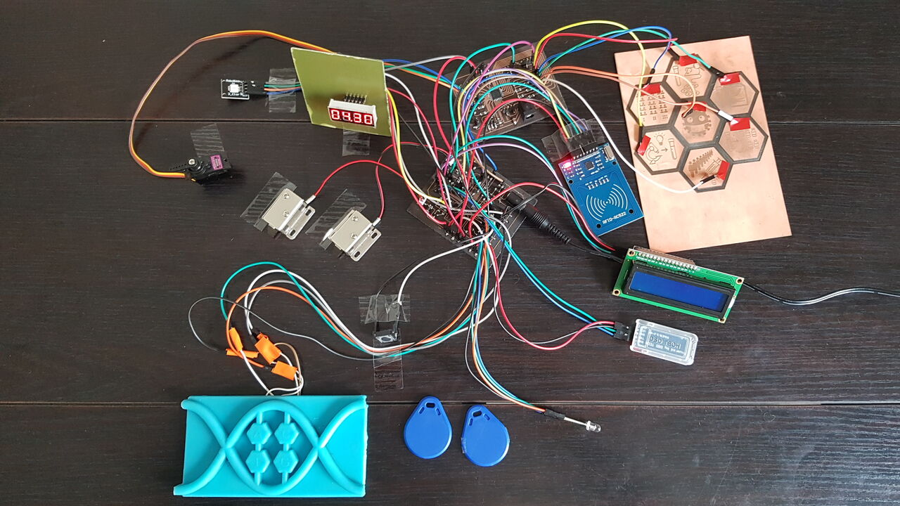
Puzzle box - Electronics integration testing
Once all components were positioned and fixed, I could connect electrical wires. Here is the result (front plate removed to show integration) :
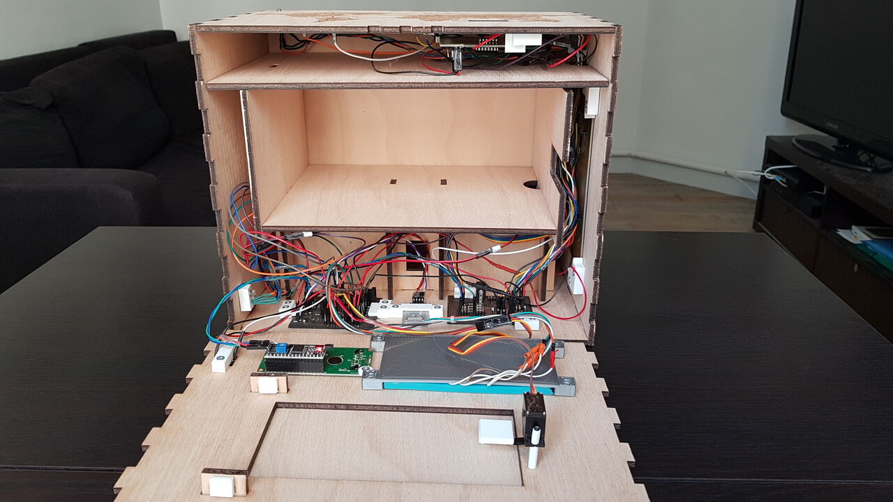
Puzzle box integration - front plate removed
Of course, when the box is close, there is no cable visible to the end user apart from the power supply cable. Here below are presented all the faces of the puzzle box :
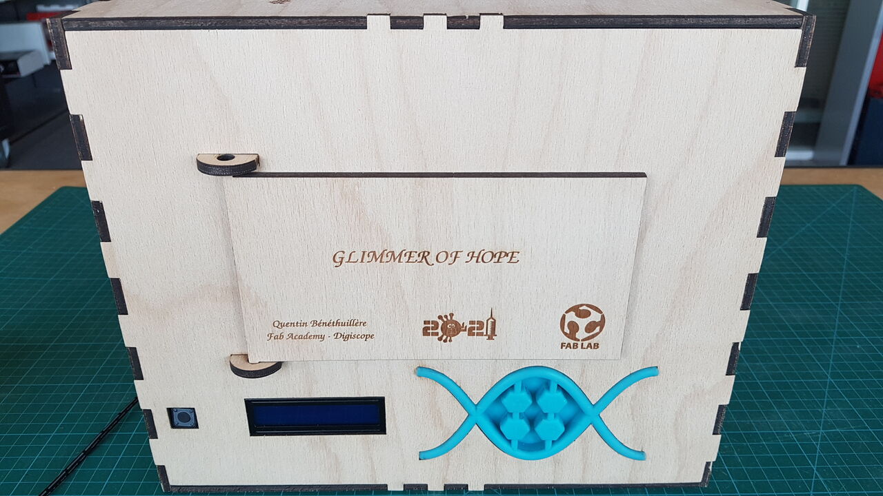
Puzzle box - Front face

Puzzle box - Top face
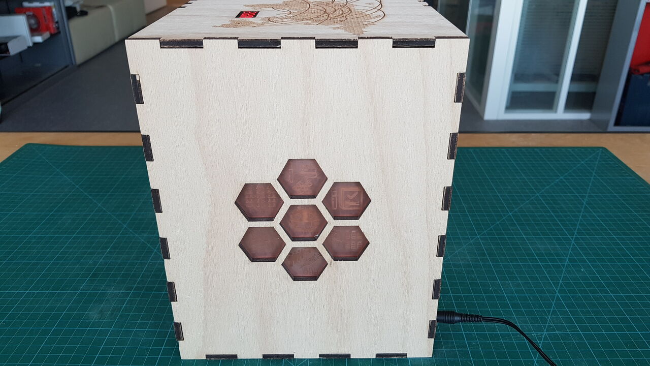
Puzzle box - Back face
Puzzle box -Left face
Puzzle box - Right face
Materials, components and cost
| Part | Quantity | Unit price (euros) | Total price (euros) | Origin |
|---|---|---|---|---|
| Beech Plywood (100x70cm) | 2 | 17.75 | 35.50 | France |
| Formlabs Tough FLTOTL03 resin | 50 mL | 143 euros/L | 7.15 | USA |
| Ultimaker PLA | - | 39.60 euros/750g | - | USA |
| Wax block (1.5”H x 3”W x 7”L) | 2 | 13.5 | 27.00 | USA |
| Silicone Smooth-On Mold Star 16 FAST | 80 mL | 16.85 euros/400mL | 3.37 | USA |
| FR4 copper plate (100x160x1.6mm) | 3 | 3.50 | 10.50 | - |
| 5V solenoid | 2 | 4.75 | 9.50 | China |
| Servomotor | 1 | 16.30 | 16.30 | USA |
| Bluetooth module HC-06 | 1 | 8.98 | 8.98 | China |
| RFID reader and tag | 1 | 2.33 | 2.33 | China |
| LCD and i2c module | 1 | 4.83 | 4.83 | Germany |
| Four 7-segments digits display | 1 | 2.33 | 2.33 | Hong Kong |
| ATmega 328P microcontroller | 2 | 1.96 | 3.92 | USA |
| ATTiny 2313 microcontroller | 1 | 1.14 | 1.14 | USA |
| Jumper wires | about 50 | 0.04 | 2 | China |
| Electronic components (resistors, capacitors, etc) | - | - | - | China |
| Screws (12x3mm) | 36 | 0.05 | 1.8 | - |
| TOTAL | 136.65 |
Fab Academy requirements
In the final project, at least 5 of the digital fabrication skills developed during the Fab Academy program must be used. Here are the technics I integrated in my puzzle box :
2D/3D modelling
- The box itself (3D frame + 2D engraved images).
- Several 3D printed supports to hold electronics components inside the box.
- Two 3D printed screwable viruses that will contain elements to progress in the game (RFID tag, and electronic wire).
- DNA keypad and associated mold for the digicode access control.
Computer control cutting
- The box itself (including drawers and all the interior pannels + 2D images engraved).
- PCBs.
Electronics design and production
- Mother board that controls everything (ATmega328P microcontroller).
- Daughter board that handles puzzle 1 and puzzle 2 (ATmega328P microcontroller).
- Side board to handle countdown function (ATTiny2313 microcontroller).
3D printing
- 2 screwable viruses (FDM + SLA).
- Supports for electronics integration.
CNC milling
- Molds for DNA keypad.
Embedded programming
- Programs that implement puzzles logics (using Arduino IDE environment).
Input devices
- Help button.
- DNA keypad.
- Capacitive sensors.
- RFID reader.
Output devices
- 4 digits display for countdown application.
- LCD to provide help messages and for DNA sequence puzzle.
- 2 solenoids to lock drawers.
- Servomotor to lock main door.
- 2 RGB LEDs to provide feedback to players’ actions.
Molding and casting
- DNA keypad.
Networking
- SPI communication : RFID reader.
- i2c communication : LCD + communication between mother board and daughter board.
- UART communication : Bluetooth module HC-06.
Interface and application programming
- Phone application to control lock mechanisms, send custom messages on the LCD, control countdown, etc.
The project had to be built using a “spiral model” approach. The model is often used by software engineers and enables gradual releases and refinement of a product through each phase of the spiral as well as the ability to build prototypes at each phase. This means that basic features are addressed first, and then extra features are added little by little in such a way that the project often comes back to a state where the product is operative.
The way I developed my final box project is fully aligned with this philosophy as presented in the beginning of the development section.
Personal guidelines
Herebelow are presented the general guidelines that I gave myself in the beginning of the project and that helped me to develop successfully my puzzle box :
- Safety: There must be no eletrical risk for the users.
- Size: Must be portable, but big enough so that several players can interact with it at the same time.
- Sequence of operations: Mechanisms cannot be solved in parralel, but rather one after the other.
- Number of mechanisms: It must be easy to add/remove mechanisms to the project.
- Scenario: The puzzle box should be built around a story and should not only be a succession of unrelated puzzles.
- Cosmetic appearance: Integrate a false back to the box/drawers/doors to hide as much as possible the electronic circuits and cables.
- Robustness: It must always be possible to open the lock mechanisms (all mechanisms should open upon power supply failure, or there should be a manual way to open any mechanism).
Project initial vision
Now that the project is completed, I feel it is interesting to compare it with the initial plans I had in the very beginning of the Fab Academy program.
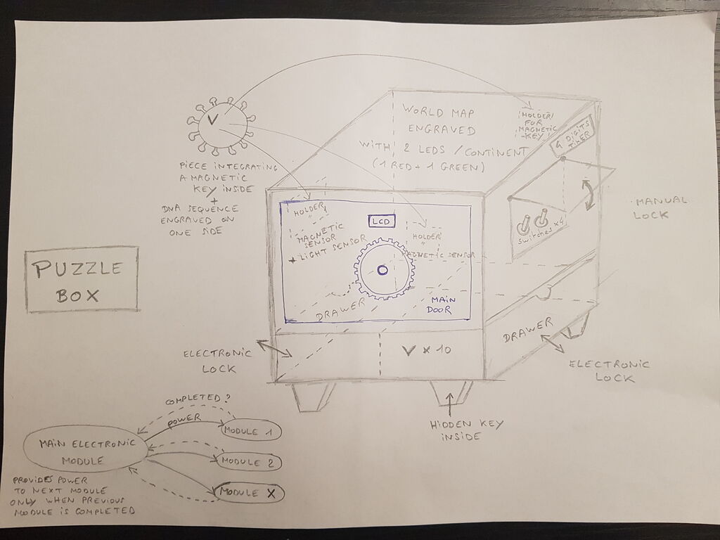
Puzzle box initial sketch - 2021/02/02
Below is the first model of the puzzle box I designed using the open-source Freecad software :
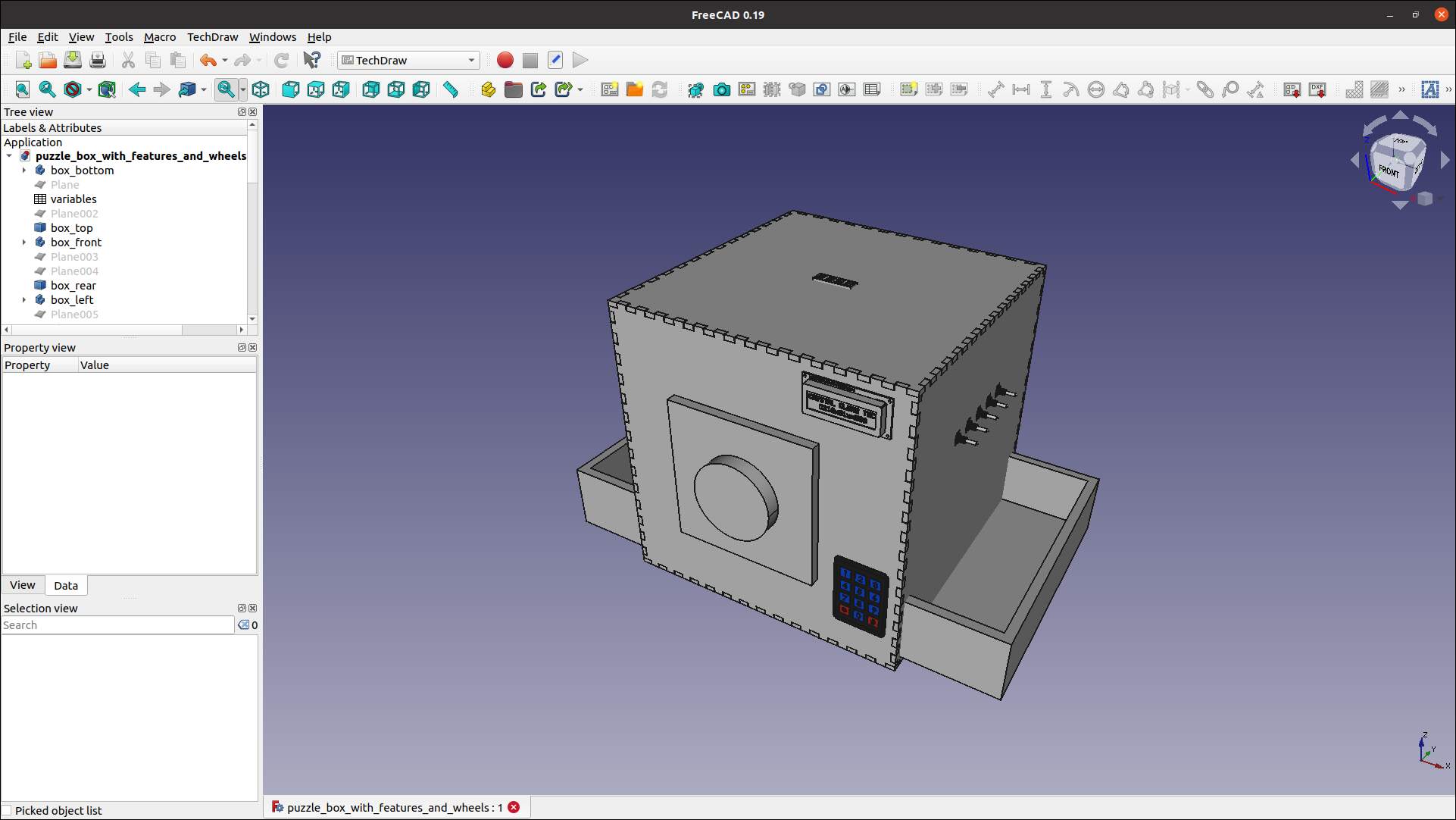
Puzzle box - front top right view - 2021/02/09
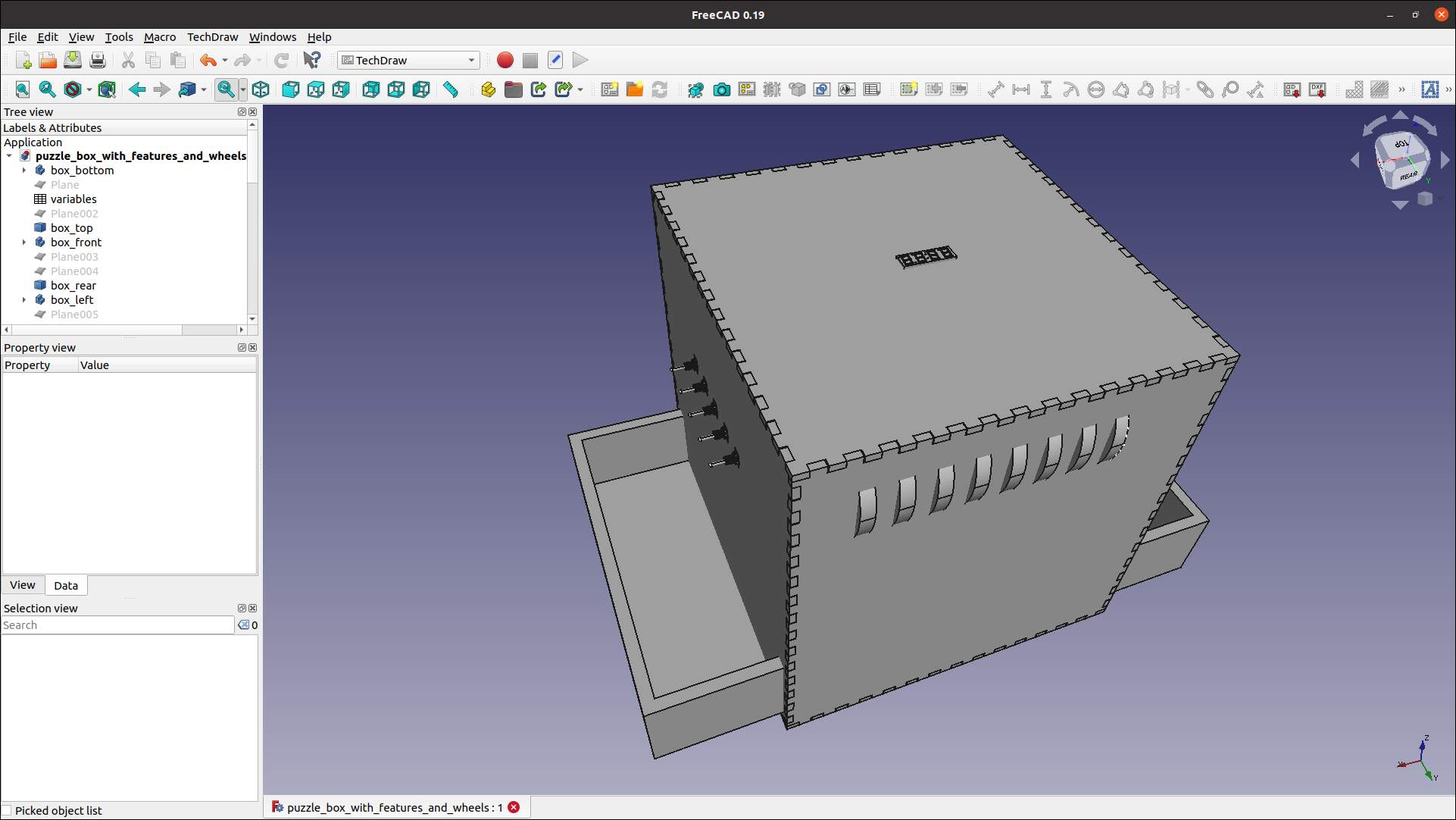
Puzzle box - rear top left view - 2021/02/09
Among the main differences I can highlight the followings :
- The switches puzzle I imagined has been replaced by the capacitive sensors puzzle (when I discovered this possibility during the input devices week I really liked it and decided to implement it).
- I abandoned the puzzle with the wheels at the back of the puzzle box as I rapidly understood that it would cause me troubles in the integration.
- I replaced the generic keypad by a custom DNA keypad I designed during the molding and casting week.
- Drawers have in the end been integrated side by side at the back of the puzzle box rather than on each side.
Source files
The source files of the work presented in this week assignment are available for download here :
- Puzzle box frame : Fusion 360 model
- Puzzle box electronics supports : stl files
- 3D virus model 1 : stl files / FreeCAD files
- 3D virus variant model : stl files / FreeCAD files
- DNA keypad model : STEP files / Fusion 360 model available on YouMagine plateform.
- Buttons PCB : Eagle HW design
- Electronics main board : .ino file / .hex file / Eagle HW design
- Electronics daughter board : .ino file / .hex file / Eagle HW design
- Electronics countdown board : .ino file / .hex file / Eagle HW design
- Puzzle box engraved images : .png files
Similar existing products
The escape room concept has turned to be so attractive that it has been declined in many different forms:
- Real-life escape rooms.
- Board games.
- Puzzle boxes.
- Virtual escape rooms.
- Movies.
Real-life escape room :
Board game :
Puzzle box :
Many examples can be found on the internet, I will just give a few examples here :
Lincoln Craven-Brightman, a student from Harvard did this lion head puzzle, and this FabAcademy cycle another student Erwin Kooi did a beautifully integrated puzzle box.
Some people on the internet such as Chris Ramsay are famous for trying to solve all sorts of puzzles, and some of them cost an incredible amount of money.
Thanks for having being through my final project documentation until the end, and I invite you all to take part in such adventures, you are likely to become big fans of it afterward.