3. Computer-controlled cutting
Assignments:
Individual assignments:
- Cut something on the vinylcutter.
- Design, lasercut, and document a parametric construction kit,
- accounting for the lasercutter kerf,
- which can be assembled in multiple ways,
- and for extra credit include elements that aren’t flat
Group assignment:
- Characterize your lasercutter’s focus, power, speed, rate, kerf, joint clearance and types.
Vinyl cutting
Vinyl cutter machine
The vinyl cutter machine available at Fablad Digiscope is the model GS24 (CAMM-1 GS-24) from Roland japanese brand.
- Cutting width : from 50mm to 700mm
- Pressure max : 350g
- Speed max : 500mm/s
Configuration set up
In order to import files directly from Inkscape to CutStudio software, it is necessary to install this dedicated plugin. As indicated in the Readme.txt, copy the files “roland_cutstudio.inx”, “roland_cutstudio.py” and “roland_cutstudio_mirror.inx” to your inkscape user extension folder (that can be found directly from inkscape by clicking on Edit -> Preferences -> System -> User extensions), and restart Inkscape. Once this configuration set up, you should be able to use the Roland CutStudio extension in your Inkscape software as shown below :
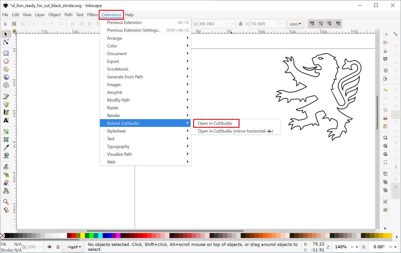
Exporting a file from Inkscape to CutStudio
As for cutting adhesive vinyl, the following settings are recommended :
- cutting force : 40 gf
- cutting speed : 3 cm/s
Realizations
It was the first time for me using a vinyl cutter machine and despite some cutting issues I have to admit that the workflow to use this machine is rather simple and straight forward.
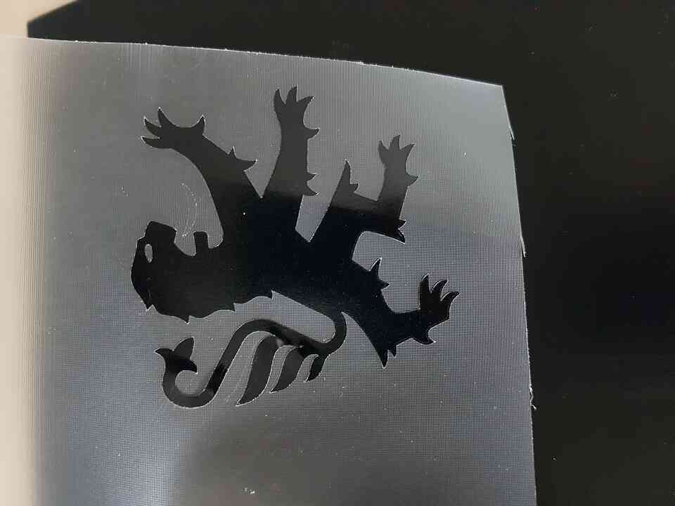
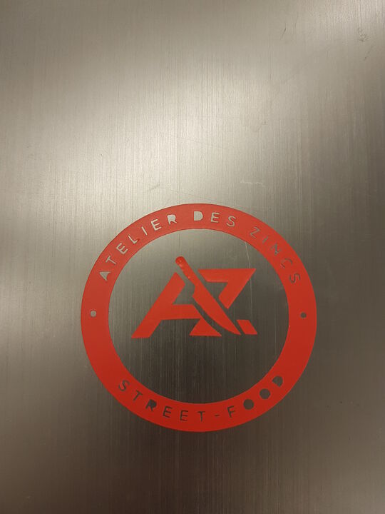
I have performed 2 realizations using adhesive vinyl, each one of them having a personal meaning. I wanted to cut something in relation with my home town, and being from Lyon (France) it did not take me long to think about the city’s emblem wich is guess what … a lion ! And of course this symbol is represented on different mediums among which the ecusson of Lyon soccer team, where I took the design from. As for my second realization I decided to cut my brother’s and cousin’s restaurant logo as I found its design particularly interesting for this excercise and also because I would be happy to help them on designing nice and customized goodies and decoration for their restaurant.
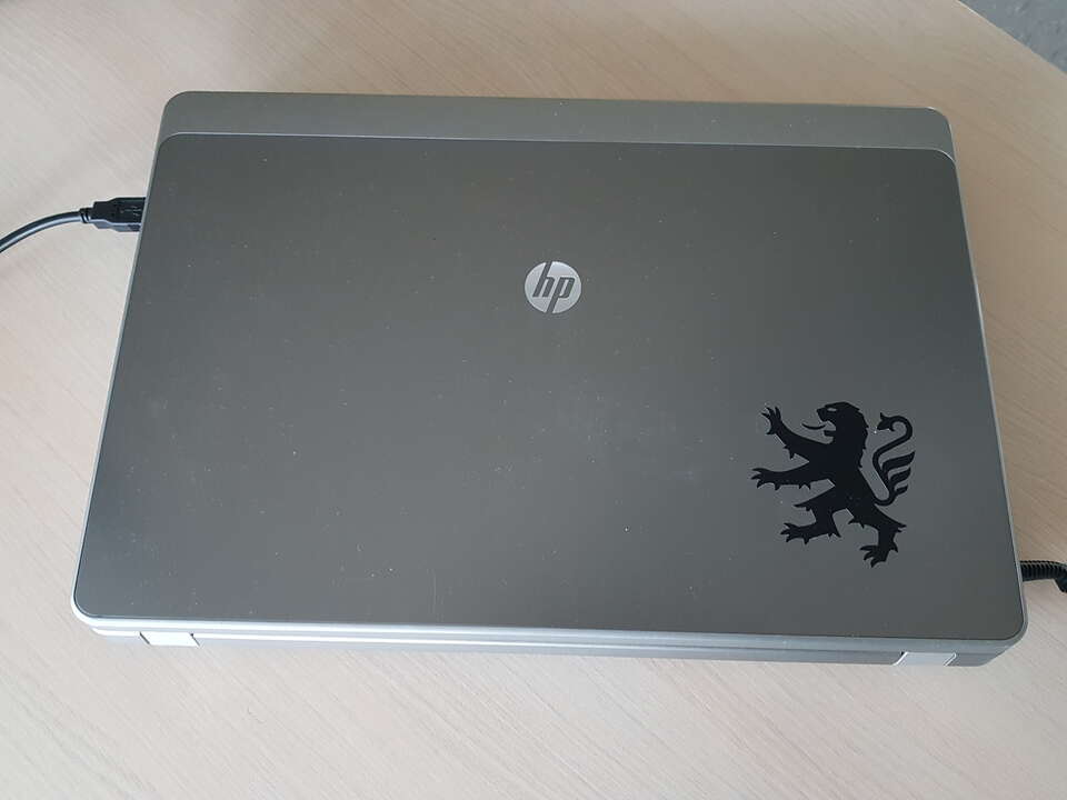
Before describing the process I followed, let’s have a look at the final result :
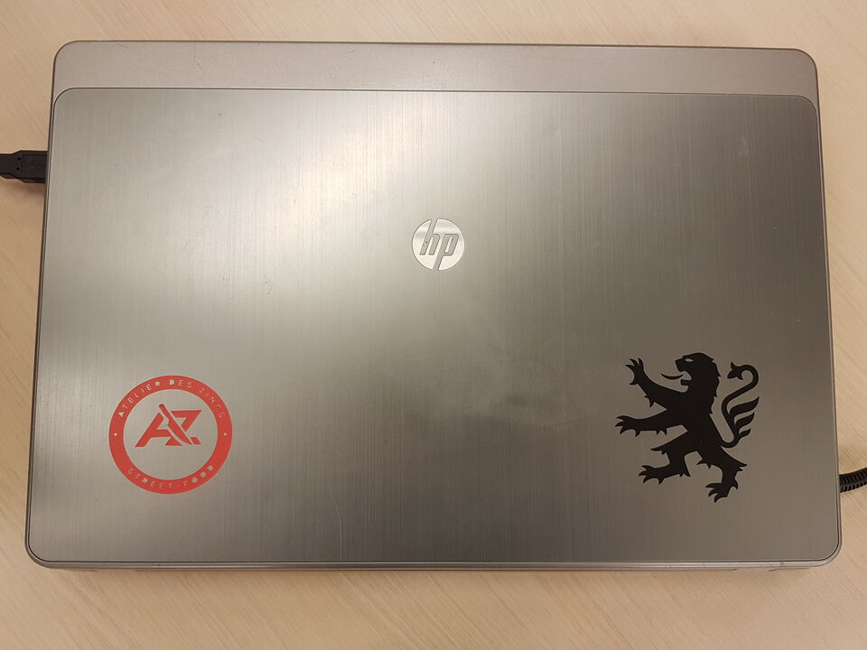
Laptop ornaments - vinyl cutter
Here is how I conducted my work :
1- Opened png images of the models in Inkscape. Here below are shown the original images I used :
| Lyon soccer team’s ecusson | “Atelier des Zincs” restaurant logo |
2- Converted the raster images into vectorial images using the “Trace Bitmap” tool of Inkscape.
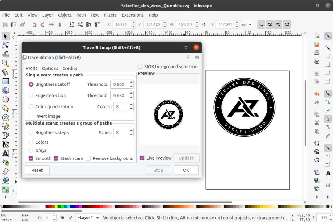
Converting raster image to vectorial image
3- Selected only the desired parts of the image composition. In my case, I only wanted to use the lion logo and not the rest of the image.
Note: on the picture below we can clearly see that the image has been converted to a path on the central black and white ecusson.
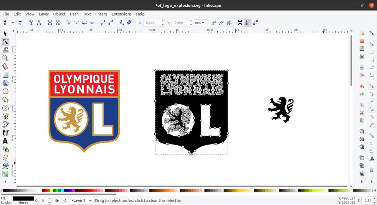
Image converted to path, and desired part selection
4- Cleant the file, scaled it to the desired dimensions (keeping the same aspect ratio) and imported the image to be cut directly from Inkscape into the dedicated vinyl cutter software called CutStudio.
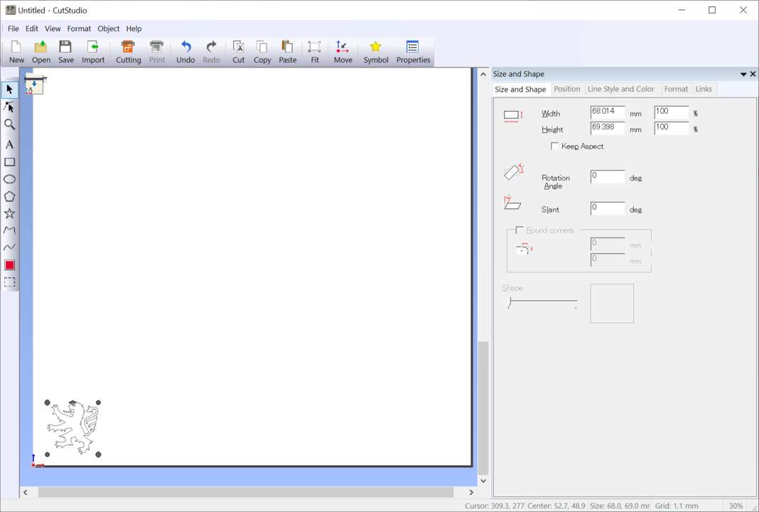
CutStudio software interface
5- Set the correct cutting parameters (see above dedicated paragraph), and execute the cut operation.
6- Took away the adhesive vinyl parts to be removed using manual sharp tools (in the case of the lion only the eye had to be removed, but in the case of the restaurant logo all the letters and the main central disk had to be removed).
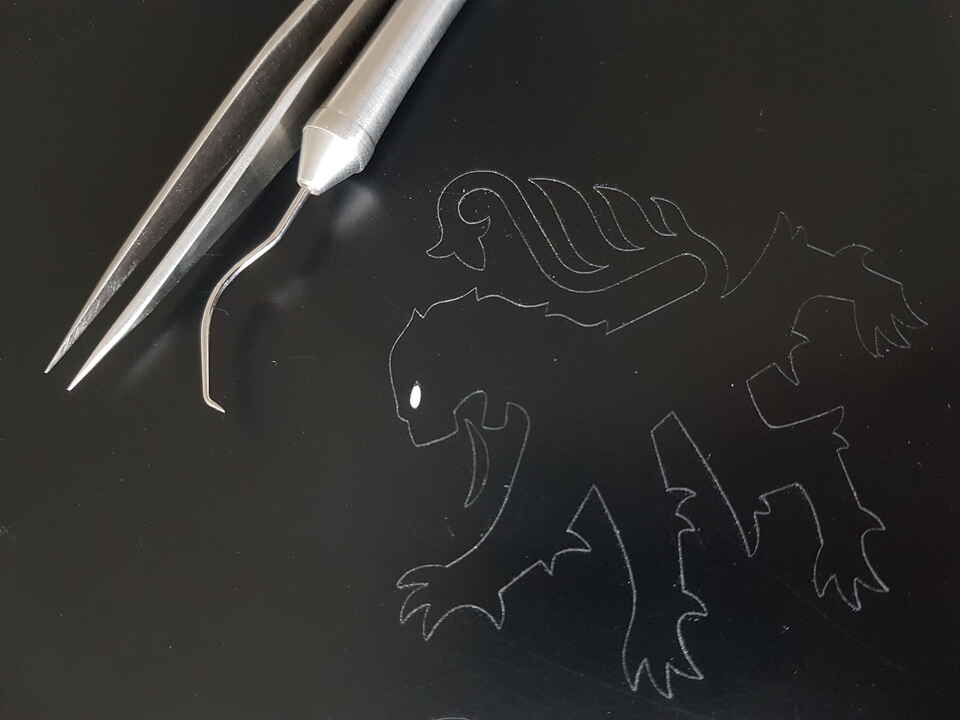
Removing undesired parts right after cut
7- Placed some transfer tape (sort of adhesive film) on top of the cut object, and used a scraper to properly apply the transfer tape and to remove air bubbles that may be stuck below.
8- Pulled gently the transfer tape to collect the vinyl object cut.
9- Positioned the object where I wanted it (on my laptop), and used the scaper again to apply some pressure on the object to be stuck.
10- Removed the transfer tape.
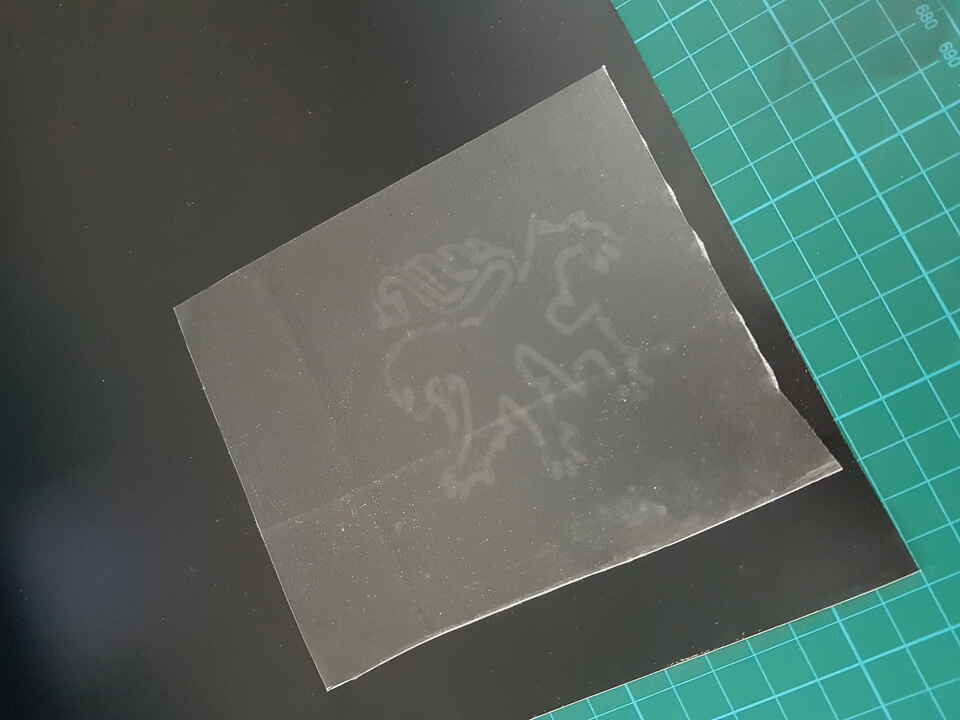 |
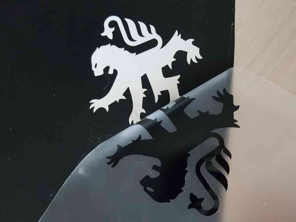 |
 |
| Under adhesive film | Removal from the film | On the adhesive film |
And the final results for the 2 realizations :
 |
 |
| Lion sticker | “Atelier des Zincs” restaurant sticker |
Issues encountered
SECTION TO BE UPDATED - difficult to collect the object after cut using the transfer tape (had to use the tweezers to help). - difficult to have a proper cut (sometimes I had to repeat twice or 3 times the cut on the same object before being able to collect it on the transfer tape). - letters were too small on the restaurant logo so I did not manage to keep the inside of letters such as “O”, “D”, “R” because two few material was left.
Explanations to difficulties : - The transfer tape had not been used for a long time, and maybe the first layer had lost some of its sticking properties. - Some filaments of vinyl material was sticking to the blade while cutting.
Laser cutting
Laser cutter machine
The laser cutter machine available at Fablad Digiscope is the Epilog Fusion M2 32 (75W) from the american company Epilog Laser.
The machines embeds both a CO2 laser and a fiber laser, the last one being used for cutting metal.
- Engraving area : 812mm x 508mm.
- Engraving max speed : 165 inches per second (4.19 m/s).
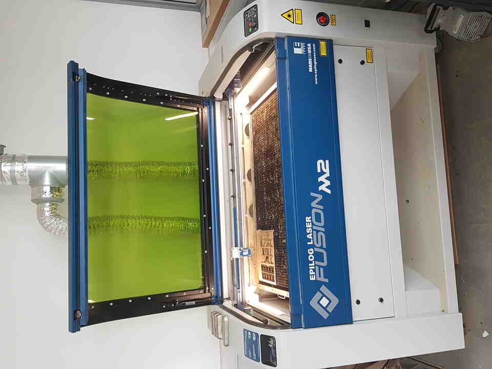
Epilog Laser - Fusion M2 32
Safety
The laser cutter is often the most dangerous machine in most of the fablabs, especially because of fire hazard, this is why a particular attention is necessary when operating this machine.
- Always stay close and watch out when laser cutting operation is in progress (risks of flames and fire).
- Always turn on the ventilation systems availabe in the machine.
- Do NOT cut unknown materials, and especially NOT PVC which produces flames and smokes that are hazardous to human and that can damage the machine lenses as well.
- Clean the cutting tray as often as possible to avoid material drops to start a fire.
Getting started with the laser cutter
Here below the few steps for operating the laser cutter :
- Turn ON the machine. The cutting board lowers automatically.
- Position the material to be cut inside the machine, at the desired location, and place some weights to keep it flat and prevent it from moving. Note : The origin (0,0) of the machine is set on the top left hand corner by default.
- Adjust the height of the cutting board using the appropriate tool (height is not the same for CO2 and fiber lasers).
- Adjust the machine origin point by moving the optical laser above the material to be cut, according to the 2D drawing to be cut.
- Prepare your cutting job in CorelDRAW (paid SW):
- Position objects correctly, adjust size if needed, select “hairline” for the stroke line type when using vector image, etc.
- Click on Print (or shortcut CTRL+P), and select the printer preferences.
- Set the type of image to be printed : Raster or Vector (if raster, select the desired DPI resolution).
- Set the cut parameters (speed / power / frequency).
- Click “Apply” and “Print”. => At this stage, the job should be available for start on the laser cutter interface.
- Make sure that ventilation systems are ON.
- Make sure that the machine door is closed and start the job.
- Watch out for the whole cutting operation.
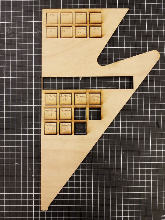
As it was the first time for me that I operate a laser cutter, I have started with simple operations, such as cutting a series of 2x2cm squares in a plywood 5mm material. The idea was to test different combination of settings (speed, power) and to compare the results obtained.
 |
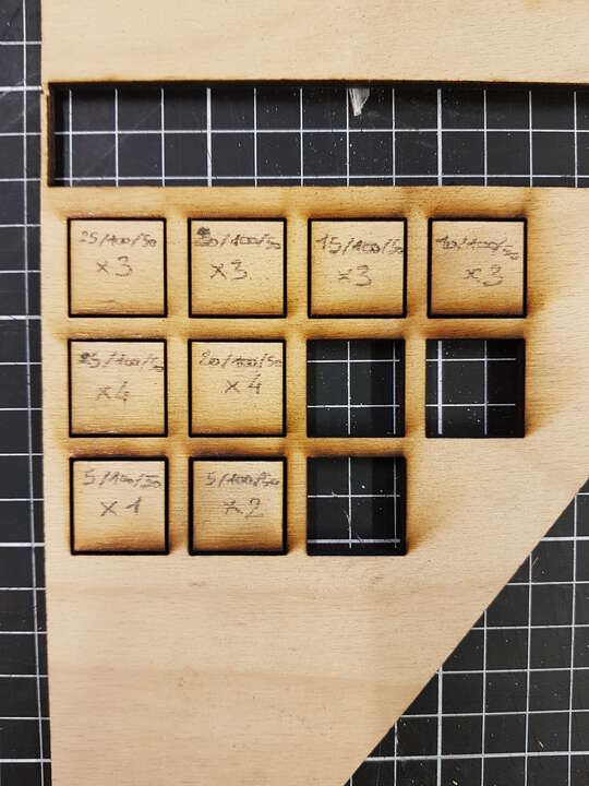 |
| Squares cuts with laser cutter (5mm plywood material) |
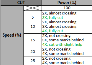
Details of the parameters used in % (speed/power/frequency, X=repetitions) |
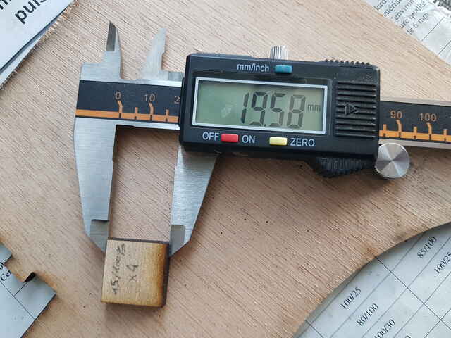
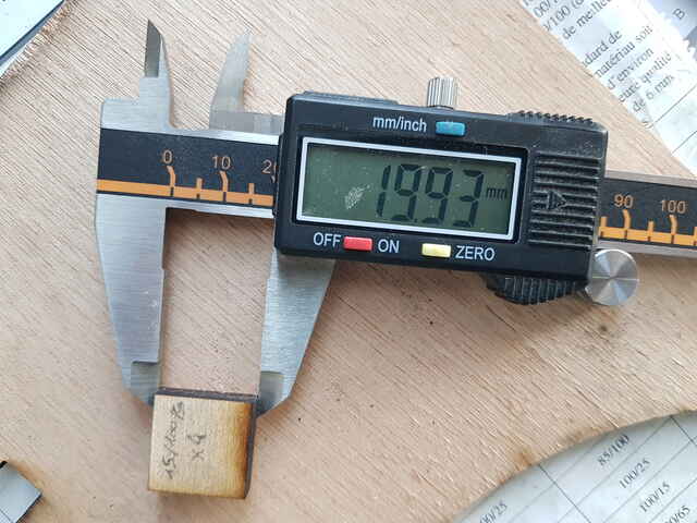
As can be seen in the summary table below, it was quite complicated to cut through this plywood material; several repetitions at very low speed and high power were needed. And the the measurement results using a digital caliper gave a quite noticeable difference of material removed between the top surface and the bottom surface of the plate (about 0.45mm difference) which made it complicated to characterize the kerf. At this moment I felt that the lense that was mounted in the laser cutter was probably not the best one for what I was trying to do (a 4.0” lense may have given better cut results), and thus I decided to stop here this introduction activity.
Plywood 5mm cutting results (X = number of repetitions)
 |
 |
| Material removed - top surface | Material removed - bottom surface |
Joints tests
Next step for me was to cut parts in 6mm cardboard in order to test some of the joints type listed in the FreeCAD template provided in the Fab Academy material and presented herehunder :
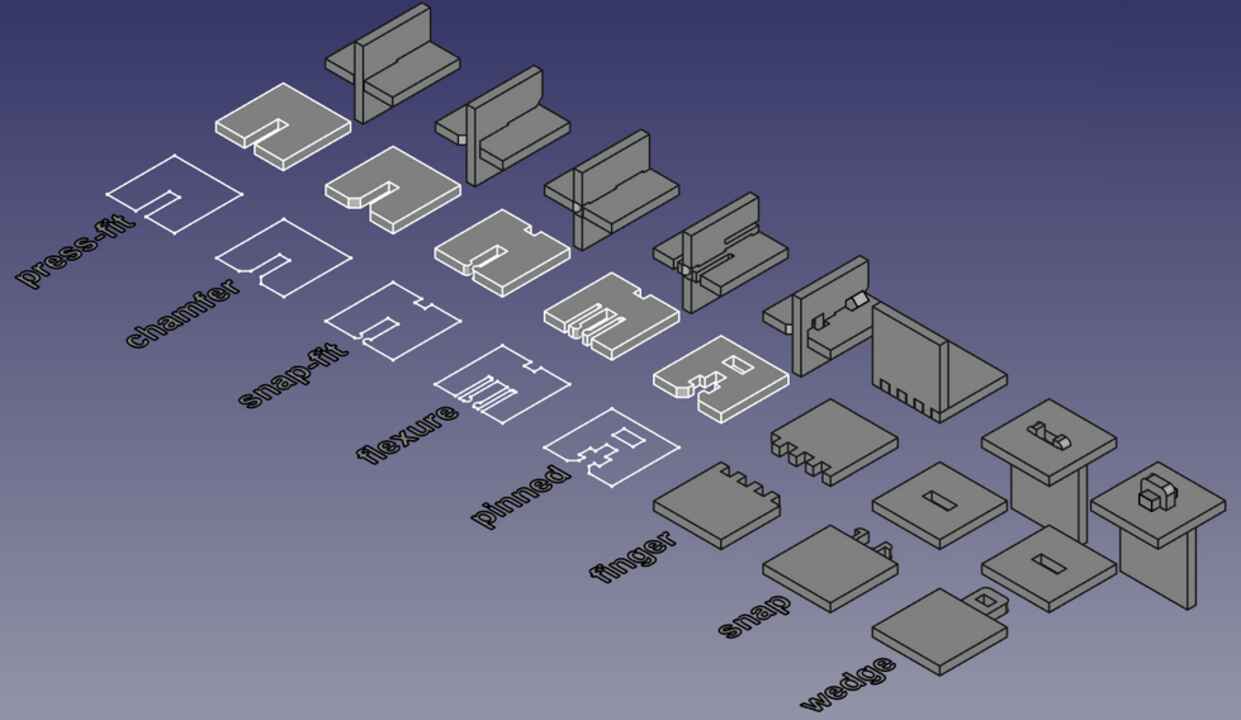
Main joints types - FreeCAD extract
The whole idea of the FreeCAD template provided is the parametric design that allows to adjust dimensions and clearances based on the material and machine used.
It permitted me to quickly obtain those pieces :
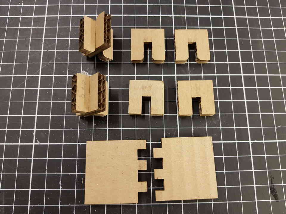
Joints realizations - cardboard 6mm
I have then played with the clearance parameter available in the FreeCAD model to adjust the slot width so that my parts fit strongly with one another.
Note : I did not perfom those adjustments tests with the fingers joints because this is something I wanted to perform on another material than cardboard, and I present it further down in this page within the section called “Press fit box assembly tests”.
Construction kit
The objective here was to design a parametric construction kit. I intentionnally decided to work with a very simple primitive that is a square with 4 slots in the center of each side to demonstrate that it already offers a wide range of construction possibilities. For the realization I have cut 40x40 mm squares in a 1.37mm thick cardboard. The material was far from being homogenous as I used pizzas cardboard, but for this kind of construction it was fair enough.
With the initial idea of building a pyramid shape, my imagination and inspiration in the end lead me to the following result :
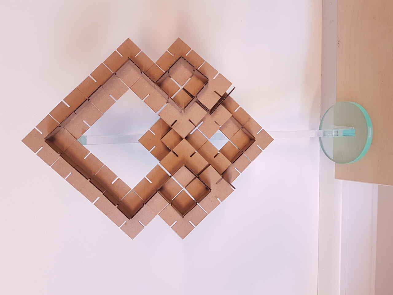
Construction kit assembly
And now some details about the design. I have used FreeCAD software to create the 2D parametric primitive I wanted. In the screenshots below, one can see a demonstration of the parametric design as the object is automatically updated when changing some values such as the square width, the material thickness or the slot adjustment to obtain the best joint possible.
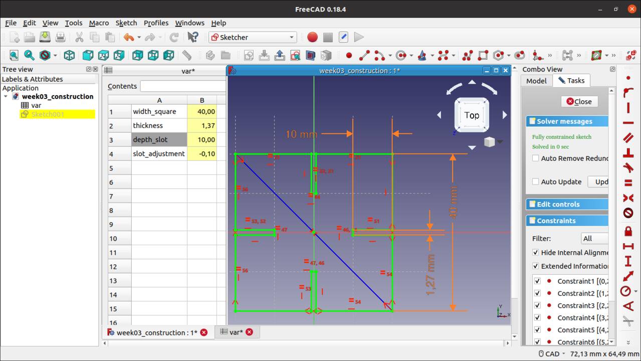
Freecad sketch - first set of parameters
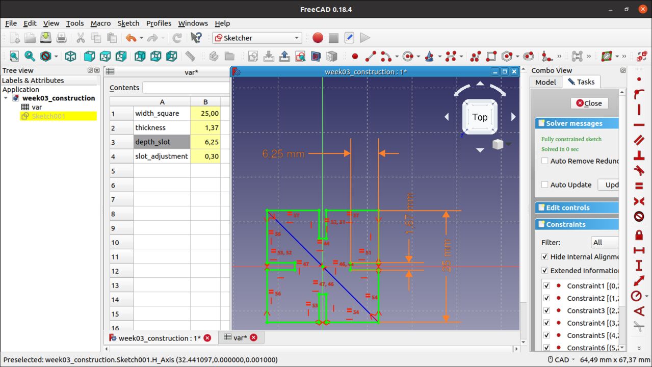
Freecad sketch - second set of parameters
FreecadCAD model is available for download here : Construction kit - FreeCAD model
Then I have first cut a batch of those pieces with different slot adjustments so that I know which adjustment was giving the best results for joints quality.
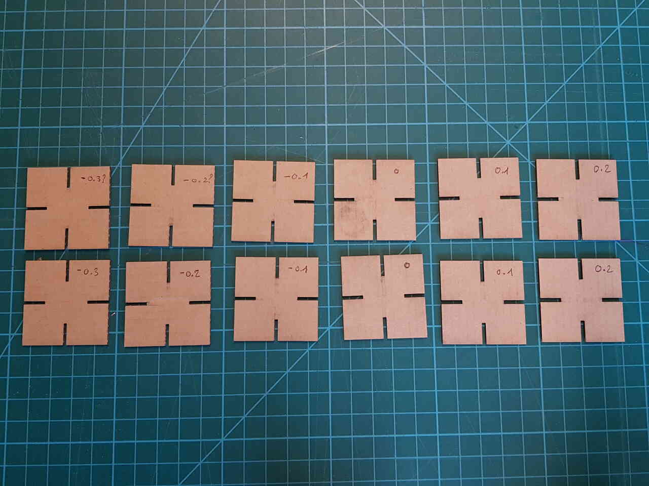
Construction kit slot adjustment tests
After finding the right adjustment (-0.1mm for the slot width), I laser cut many of those pieces.
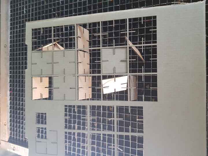
Construction kit - lifting plate after laser-cutting (speed:40%, power:50%)
And then I was ready to play ! Below some pictures of my construction in progress.
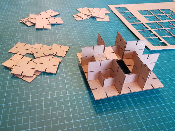 |
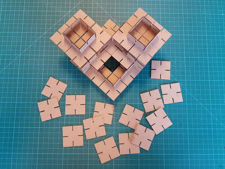 |
| Construction kit assembly in progress | Construction kit assembly - first face shape |
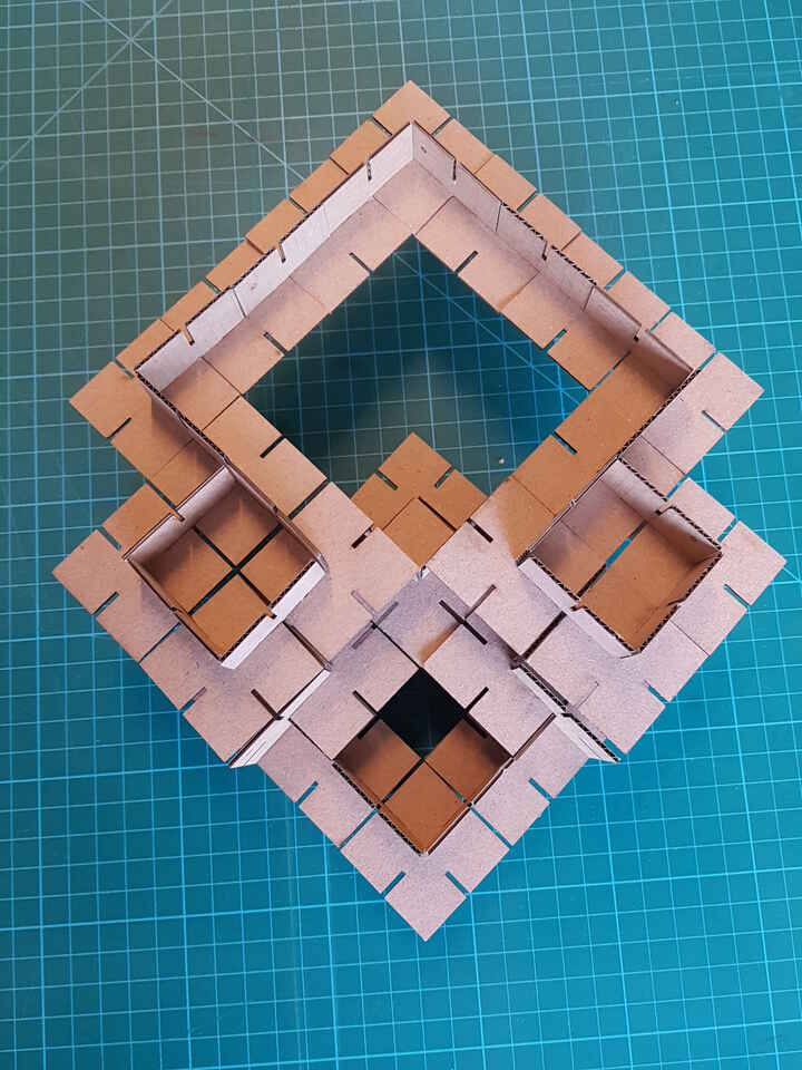
Construction kit - final assembly
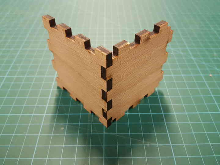
Press fit box assembly tests - kerf evaluation
For my final project I need to make a 5mm plywood press fit box, and as an introduction to it I wanted to test assembling two parts with fingers joints. The main purpose here was to find the correct adjustments (especially accounting for kerf) in my parts design to obtain the best joint possible (not too loose, not too tight). In order to do so, I have created in FreeCAD two parametrics plates with different slots adjustments on each side of the square.
First of all the parametric design can be observed in the screenshots below, where as an example the number of notches has been modified in one axis :
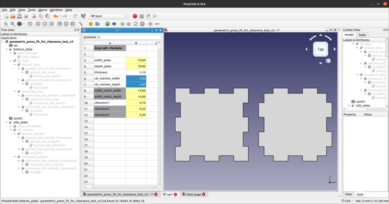 |
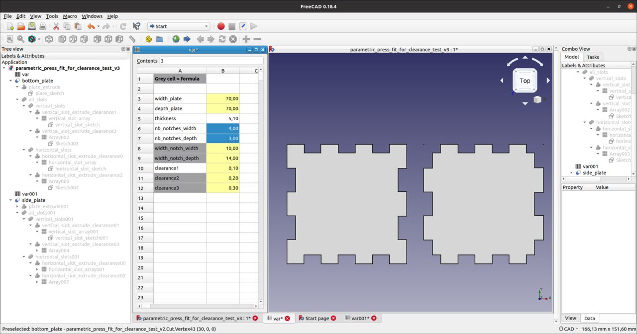 |
| Parametric design - 3 notches on all sides | Parametric design - 3 notches on one axis, and 4 on the other axis |
And for giving a better understanding of my plates design, have a look at the screenshot herehunder where I voluntarily exagerated a lot the slot adjustment difference between the different sides of the plates :
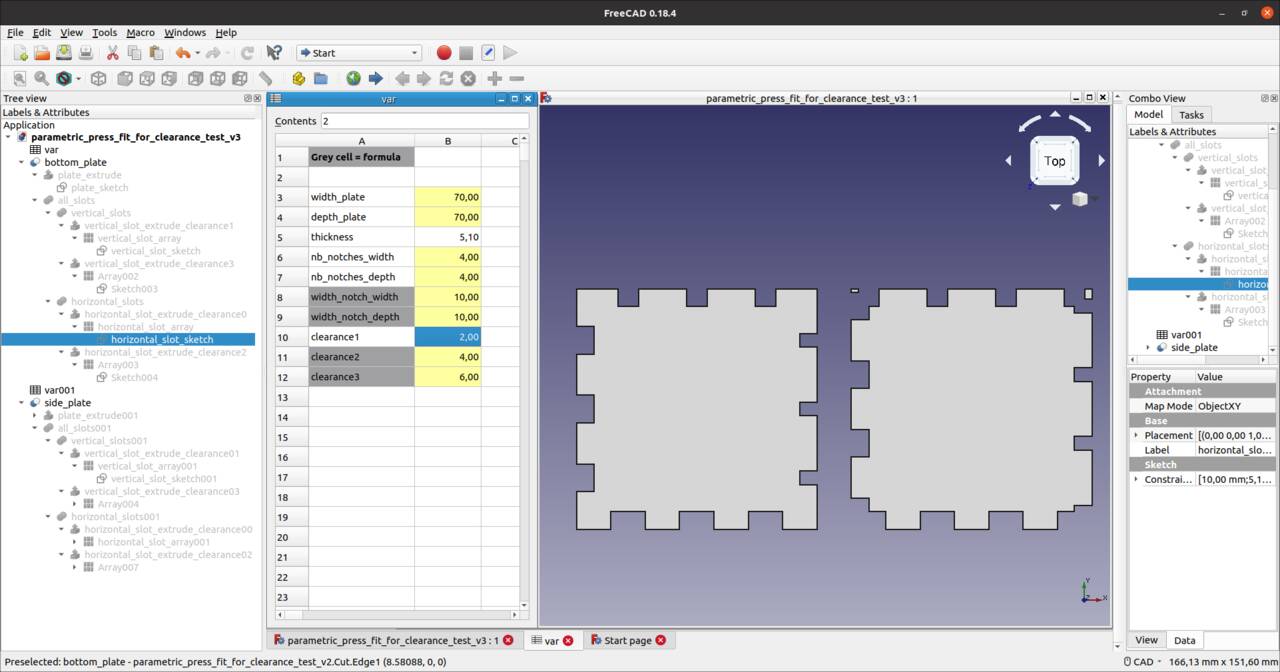
FreeDAD design to test press fit adjustment
| Side | Real slot adjustment | Exgerated slot adjustment in the example above |
|---|---|---|
| bottom | 0mm | 0mm |
| left | 0.1mm | 2mm |
| top | 0.2mm | 4mm |
| right | 0.3mm | 6mm |
FreecadCAD model is available for download here : Parametric press fit clearance test - FreeCAD model
I then laser cut the two 70x70mm plates on a 5.1mm thick plywood material. The dimensions have been chosen so that all slots and notches should be 10mm wide.
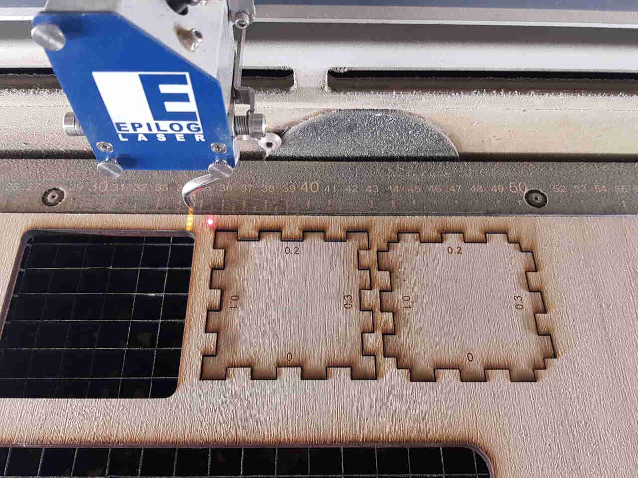
Laser cutting press fit parts for slots adjustments
(2 repetitions with speed:20%, power:100%)
After trying to assemble the parts on the different sides, I came up with the result that the ideal slot adjustment for obtaining the best press fit joint with this material and laser cutter is 0.2mm.
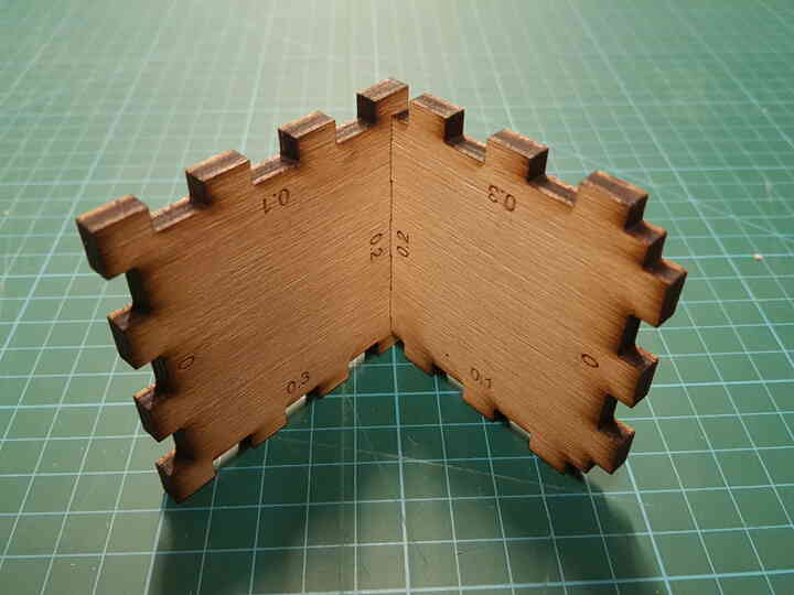 |
 |
| Press fit assembly - Inside | Press fit assembly - Outside |
Now that I have this information, I can set the correct parameters in my design for making my complete box (which I have not had time to do yet).
Note : After measurements using a digital caliper and nesting tests it turned out that the cut is not a perfect straight line in the material. It rather presents a trapezoidal shape like the one shown here:
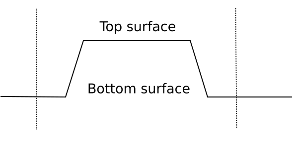
Trapezoidal shape after laser cut in 5mm plywood)
| Slot adjustment | Outside part - Notch width - Top | Part - slot width - Top | Outside part - Notch width - Bottom | Part - slot width - Bottom |
|---|---|---|---|---|
| 0mm | 9.68mm | 10.48mm | 9.83mm | 10.32mm |
| 0.3mm | 9.37mm | 10.05mm | 9.57mm | 9.90mm |
The measurements presented in the table above reveals that with the parameters used for performing this laser cutting, the kerf is in average 0.37mm on the top surface of the cut, and rather 0.22mm on the bottom surface of the cut. It is also possible to notice that with the slot adjustment of 0.3mm, the slots of the cut part are slightly < 10.00mm which makes it impossible to fit with their notches counterparts.
As already mentioned above in this page, the use of a 4” lense may give better results on this topic. This is something I would like to try soon.
Characterization of the laser cutter for engraving purposes
In order to characterize Fablab Digiscope laser cutter on a poplar 3mm material as a group assignment we have decided to create a matrix of 10x10mm squares engraved over the laser cutter power and speed ranges with steps of 10%. The result obtained is the following :
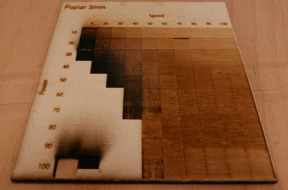
Engraving characterization - Poplar 3mm - Epilog Fusion M2 32 (75W)
This engraving matrix has been generated by laser cutting black squares filled in as raster images. It took almost 45 minutes to complete this task, as raster images are longer to engrave/cut than vector images because they are composed of pixels and not only paths and thus the laser has to go through all those pixels. Also in order to facilitate our job, we have used the color mapping function in CorelDraw software for engraving several squares with different laser parameters in the same job.
Lamifold Design
To go further with laser cutting, I recommend to read this fascinating article about Lamifold which offers a very interesting design and fabrication workflow for making 3D objects with degrees of freedom, using only a laser cutter machine, and without requiring any external parts (such as springs, bolts, etc). The main ideas of this design are the following : - Abolishing the post production manipulation for assembling the parts together. - Abolishing the design dependency to external off-the-shelf parts such as springs, bolts, etc. - Making this intricate design as smooth as possible to end users through a dedicated software environment implemented as a plugin for Autodesk Fusion 360.
Rotation, sliding and hinge are the main mechanisms available at the moment but further development could result in the extension to new mechanisms allowing other movements. LamiFold design is especially meant for fabrication with sheets of laminated wood; layers of material (usually 3) are stacked in the laser cutter, where they are cut and selectively glued with the layer underneath one by one (using stencil to facilitate the glue application with accuracy). The complete process is as follow :
- Design the 3D object in Fusion 360 using the Lamifold pluggin.
- Fine-tune the functional object and test its functionality (still in Fusion 360).
- Export the 3D design to 2D sketches ready for cutting through the Lamifold pluggin.
- Produce the 3D object using a laser cutter.
- a. Cut the first layer of material.
- b. Cut the appropriate glue stencil for preparing next step.
- c. Tape the glue stencil on the first layer of material and apply glue accordingly.
- d. Position the second layer of material on top of the first layer, and wait that the glue cures.
- e. Cut the second layer of material.
- f. Cut the appropriate glue stencil for preparing next step.
- g. Tape the glue stencil on the second layer of material and apply glue accordingly.
- h. Position the 3rd layer of material on top of the second layer, and wait that the glue cures.
Some details on the motion mechanisms are presented here:
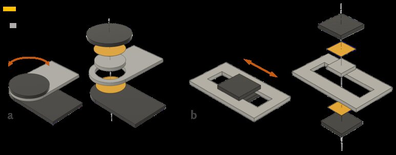
Lamifold design - continuous mechanisms
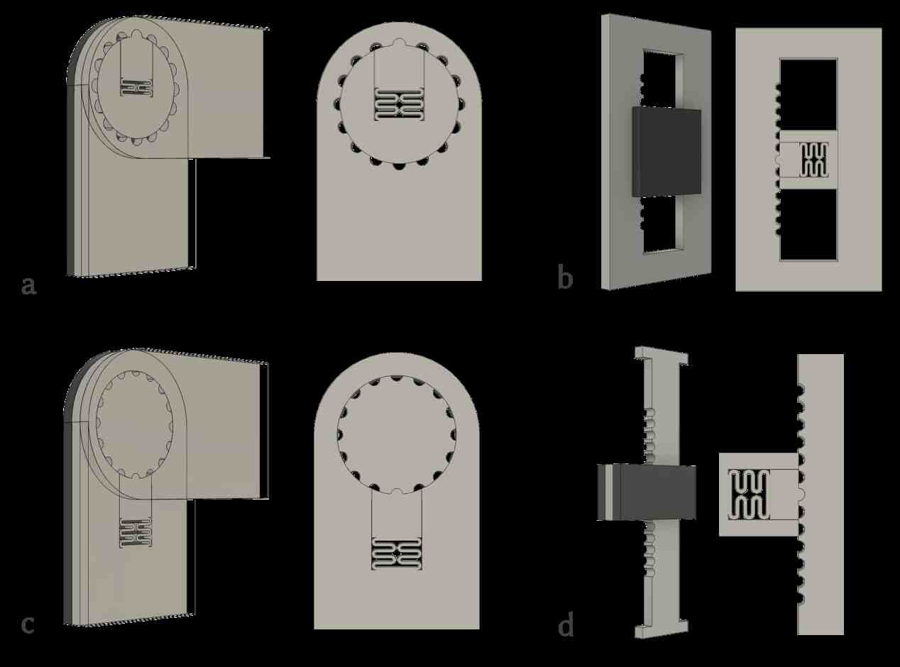
Lamifold design - detent mechanisms
See below a few examples of what can be achieved using this design approach:
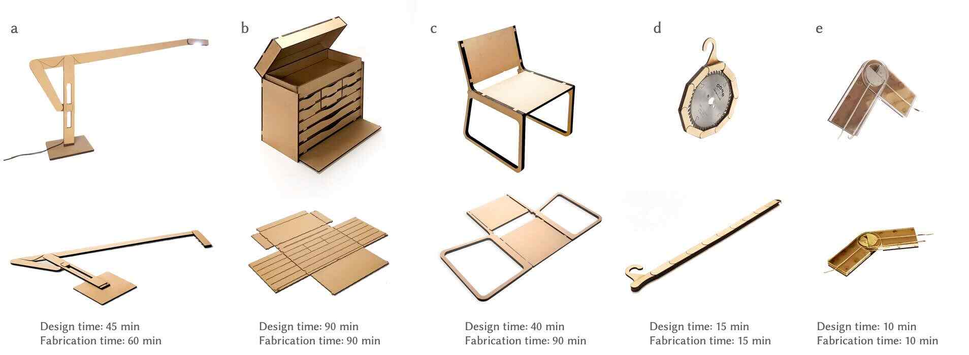
Lamifold design examples
Source files
The source files of the work presented in this week assignment are available for download here :