7. Computer-controlled machining
Assignments:
Individual assignment:
- Make (design+mill+assemble) something big.
Group assignment:
- Test runout, alignment, speeds, feeds, and toolpaths for your machine.
CNC introduction
Machine presentation
The CNC machine available at fablab Digiscope is a ShopBot Desktop. Its work area is 24” x 18”.
ShopBot Desktop
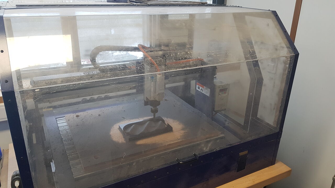
3D milling demonstration
To start this week, we had the chance to have an introduction to CNC and a 3D milling demonstration by Alexandre Beaudouin, designer and specialist in the use of CNC machines for making sophisticated wooden furnitures. Please find below few pictures of this demonstration concluded with the realization of a very beautiful object.
 |
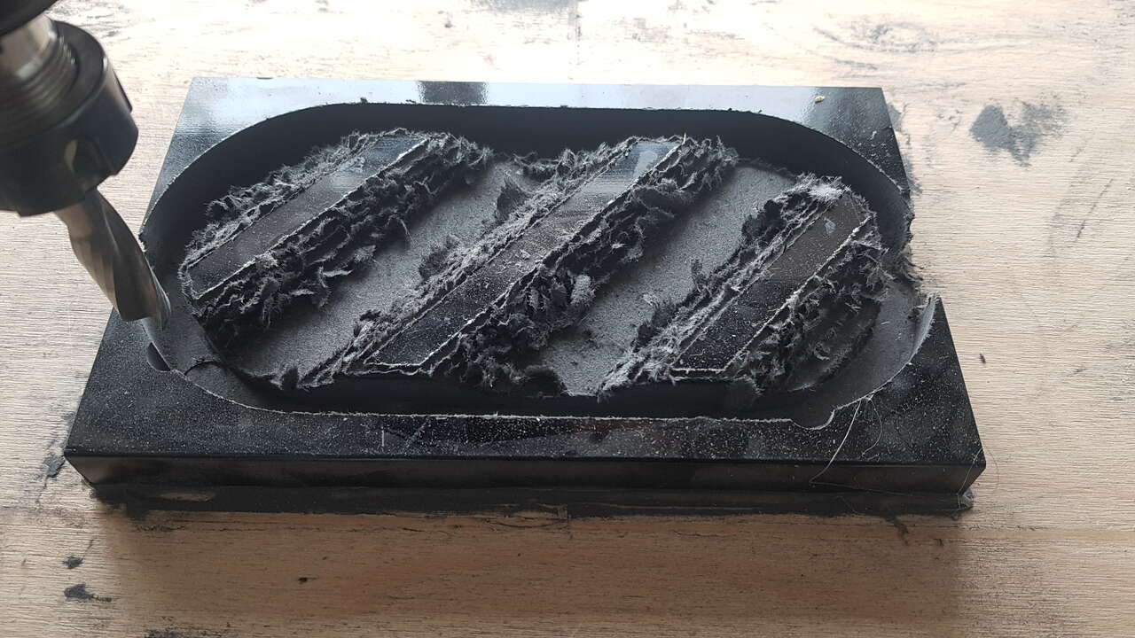 |
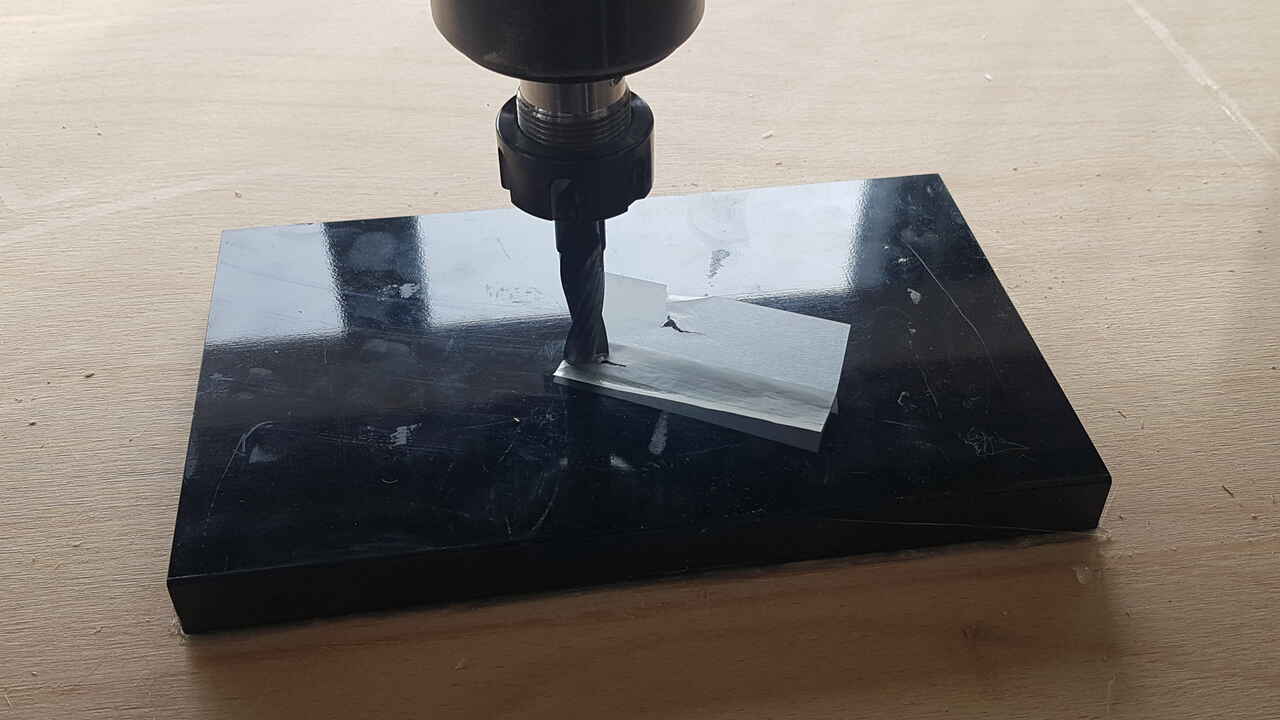
| Initial material | 3D milling - Roughing pass |
 |
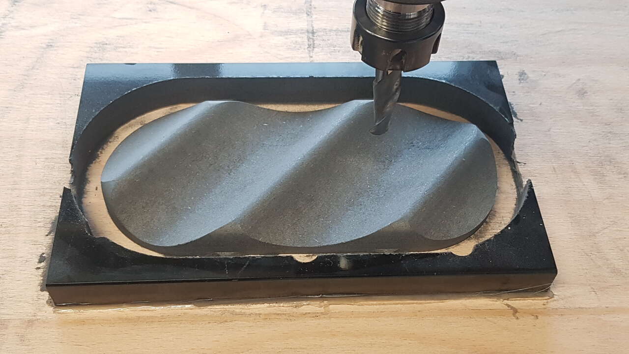 |
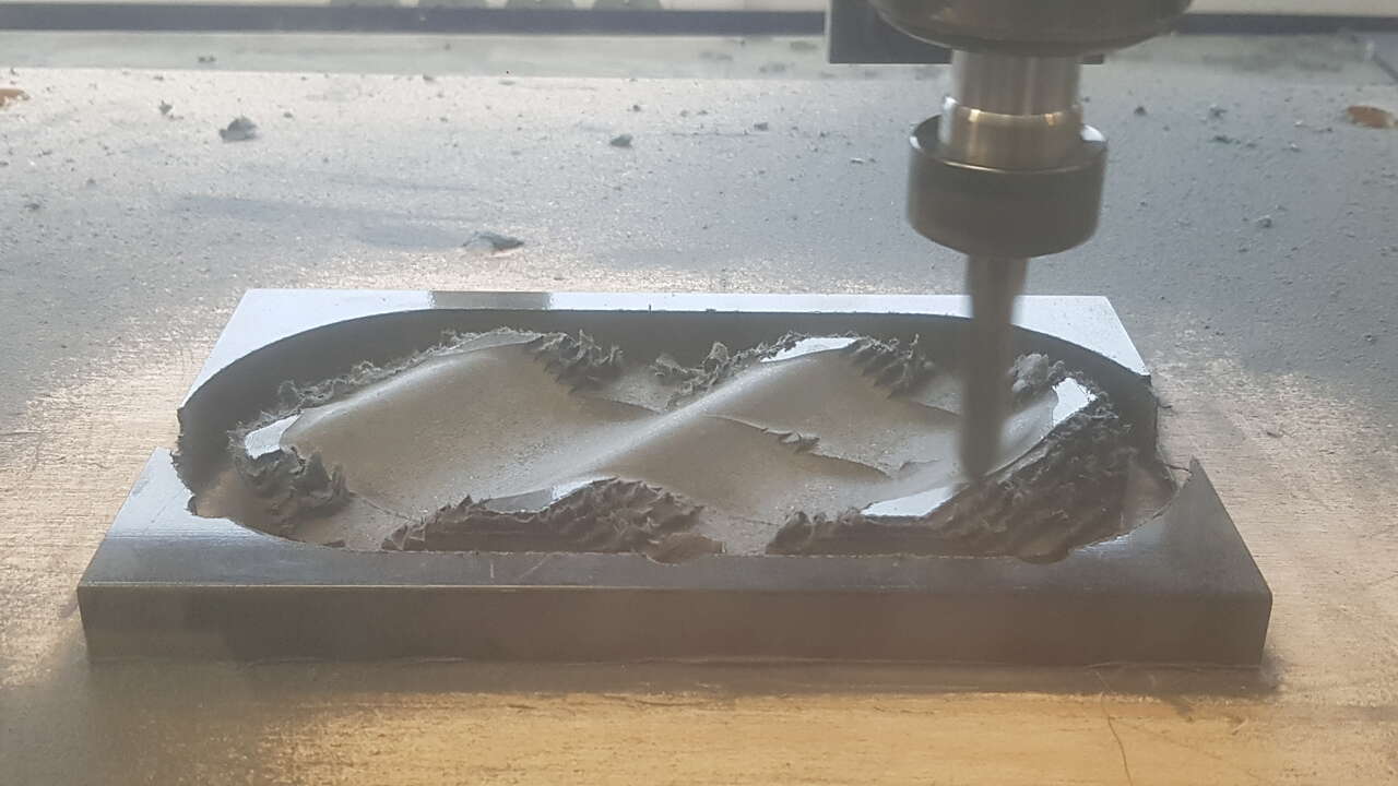
| 3D milling - Finishing pass | 3D milling - Job completed |
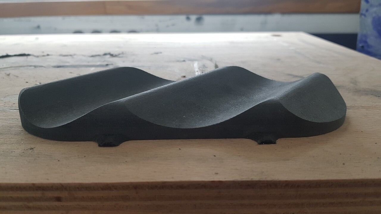
3D milling - Final result
Thank you very much Alexandre for this really interesting session !
Procedures
Job preparation
For this introduction week, we will mainly focused on 2D or 2.5D milling, so I will briefly present the preparation worklow for this type of work. All those steps will be developed with images in the section dedicated to my shelf realization.
- Design a 2D or 3D model in a CAD software, and export it as a 2D vector file (.svg for example).
- Open this vector file in a software (such as VCarve of Fusion360) to prepare the file for the CNC router. Note: Some software such as Fusion 360 offers advanced possbilities to perform both steps 1 and 2, but this is not the case for all softwares.
- Set the material properties, especially dimensions on all 3 axis.
- Select the milling tool to be used in the software and set the corresponding cutting parameters : tool diameter, number of flutes, pass depth, stepover, spindle speed, feed rate, plunge rate. This website is particularly helpful for setting those parameters.
- Position the objects to be cut on the material (this action is called “nesting”), and select the milling operations to be executed.
- Add tabs if needed (little supports to hold any parts of material in place during the whole cutting operation).
- Check the toolpath preview.
Next step, if not already done is to prepare the CNC machine.
Installation, configuration and execution
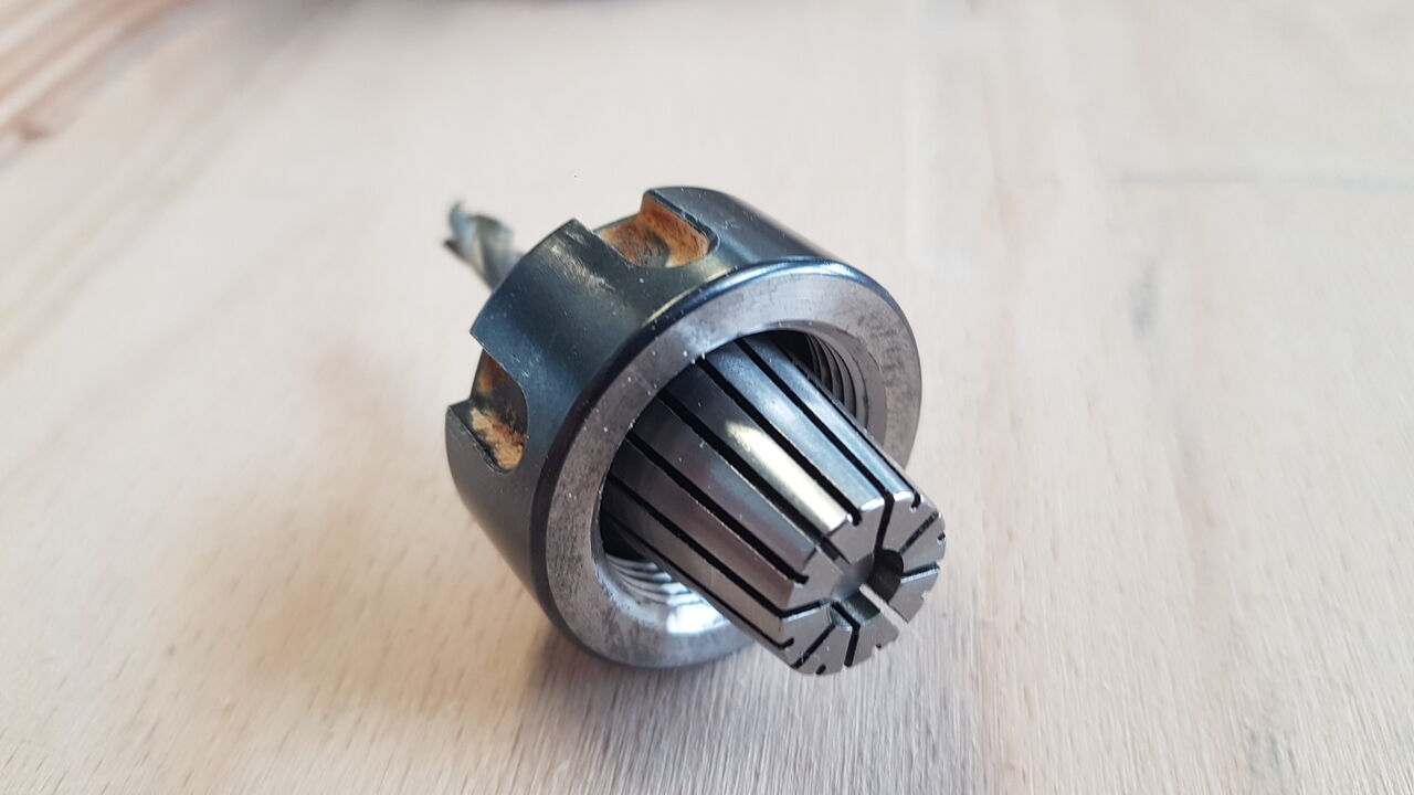
1 - Select the appropriate end-mill (type, size, etc) and corresponding collet for the job to be performed. Insert in this order the collet into the collet nut, and then the end-mill into the collet. As for how deep the end-mill should be fitted into the collet, this depends on the tool used; but as general rules leave some margin between the end-mill flutes and the collet entry, and if possible insert the end-mill until it reaches 3mm before the back side of the collet, it must not go through the collet entirely. Then the assembly must be tightened on the spindle using the 2 appropriate wrenches. Theoretically, each type of collet should be tighten with a particular torque.
 |
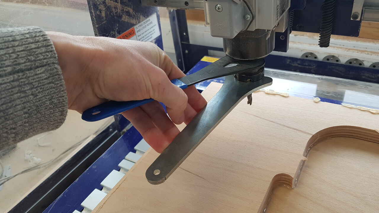 |
| End-mill and collet assembly | Tightening the assembly |
2 - Install the material to be milled on top of the sacrificial layer (which goal is to protect the machine bed), and fix it thouroughly. Several techniques can be used on that purpose such as glue, clamps or nails. In our lab we use a glue gun to fix the material as it prevents any critical issue that may happen when the end mill accidently comes across a nail. Important note here, the glue must be placed on the side of the material, and not under otherwise the material will not present a flat surface any longer.
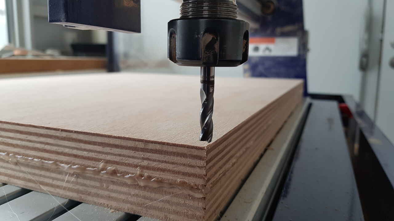
3 - Set the origin of the material on all 3 axis. First start to zeroe the x and y axis (with the end-mill slightly above the material), and then zeroe the vertical axis (z). This procedure is done through the software to control the CNC machine, in our case the ShopBot Control Software.
Warning: A great care is required when calibrating the z axis, as the end-mill and spindle can get damaged if the end-mill is plunged into the material while it is not spinning.
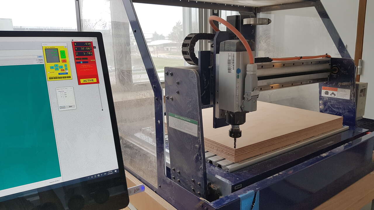
Calibration of the material origin
 |
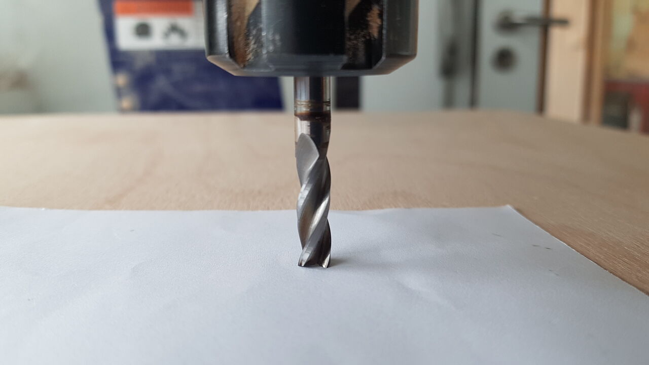 |
| Calibrating origin on x,y axes | Calibrating origin on z axis |
4 - Make sure that the spindle frequency/rpm is set as expected on the machine.
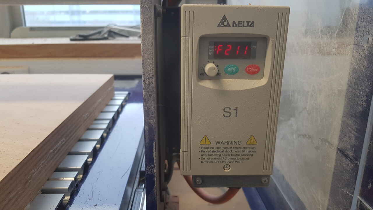
Spindle frequency - ShopBot
5 - Start the milling job.
Note: Before starting the real milling, for safety reasons, it is advised to perform an air pass. Bascially this consists of voluntarily offseting the z-origin to a high value (like 30mm), to start the job and check that the tool is following the expected path on the xy plane. By doing so, this permits to easily identify issues such as tool exceeding the material boundaries, and to correct them before starting the real milling operation. This improves safety, can save a lot of time and avoid wasting material due to silly mistakes.
Warning: Always stay close-by when the CNC machine is in operation as there are a lot of things that can go wrong and that can have very serious consequences.
CNC main parameters
In this section I will introduce the key points when it comes to CNC milling.
- Materials: a lot of different materials can be milled such as foam, MDF, plywood, OSB, HDPE, polycarbonate, garolite, aluminium, etc. CNC max/min speeds and horse power combined with the cutting tool used determined what can be cut.
- End-mills are mainly designed to cut sideway (even if most end-mills can cut both horizontally and vertically). In that sense, it differs from drill bits which are designed to cut vertically. As a result, it is more appropriate to apply ramps (moving down ward and transversly at the same time) when using end-mills.
- Types of bits: a hundreds of different types exist but we can identify 4 main categories :
- Sign-making bits (also called V-bit) : typically present an angle of 30°, 60° or 90°.
- Profile bits : make nice edges, profiles.
- Straight edge bits : typically present 1 or 2 blade(s) on each side.
- End-mills : the most popular types of bits for CNCs, presenting spirals. Among this categories can be found flat end-mills which are used when cutting on a flat surface, and ball end-mills used for curvy shapes.
- Number of flutes: the greater the number of flutes, the more accurate the cut is, but less material is being removed. Single and double flutes end mill are preferred when it comes to roughing, whereas 3 flutes or more are recommended for a clean finish.
- Direction of displacement: the tool is always spinning clockwise, but laterally it can be moved either forward or backward.
- Conventional (from right to left) : typically used for rough cutting. It puts a lot of pressure on the tool.
- Climb (from left to right) : offers a better finish.
- Type of cut:
- Up-cup : makes the material chips go upwards. This leaves a clean down edge, but a rough up edge. Warning : This type of cut tends to lift the material out of the table so make sure that the material is properly clamped.
- Down-cut : makes the material chips go downwards. This leaves a clean top edge, but a rough down edge. It holds the material down to the table, but as it is more difficult for the chips to get taken away, it can increase the risk of fire with some materials.
- Compression (up & down cut): those tools present an up-cut tip and a down-cut side. Usually those bits are used to remove about 0.5 inch of material for each pass.
- Stepover: defines how far the mill moves on the side between two rotations. Usually never more than half of the mill diameter.
- Stepdown: defines the vertical distance the mill goes down between two passes. Usually never more than half of the mill diameter.
Hereunder a picture of the tools used during the 3D milling demonstration presented in the beginning of this page (note : the 8mm diameter tool on the left in the picture below was not used during the demo).
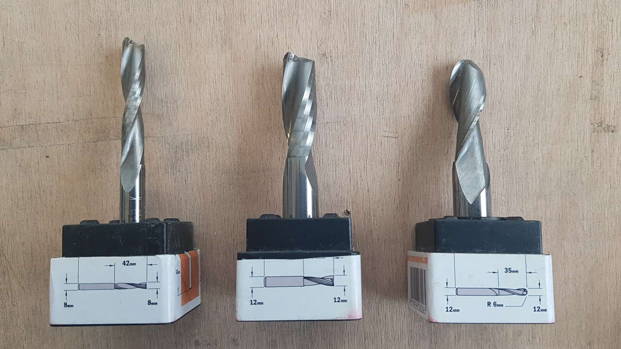
End-mills samples
Shelf realization
As the purpose of this week was to make something big and that our ShopBot CNC machine offers a rather limited work area of 24”x18”, I had to make something that could be assembled with smaller parts. In the end, I decided to realize a press fit shelf, that does not need any glue or screws to stand.
Design
I designed a fully parametric shelf in FreeCAD software. As a starting point, I designed the assembly presented below with simple transversal posts.
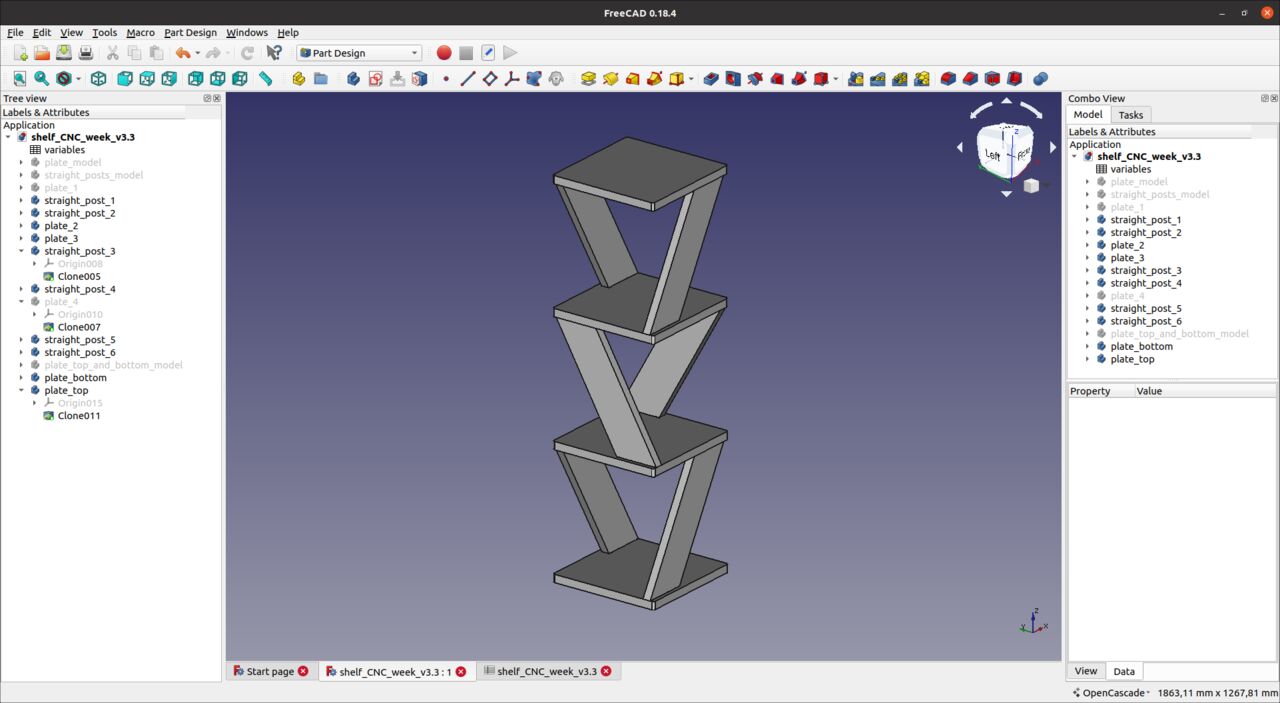
Shelf design for CNC milling - Freecad
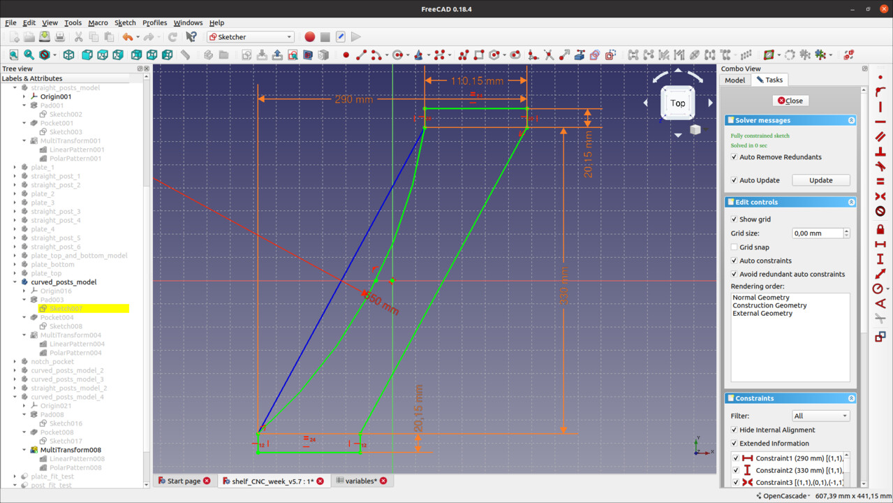
Then I tought that it could be original to use different shapes and height for the posts of each shelf level. I came up with the design of those two other types of posts :
 |
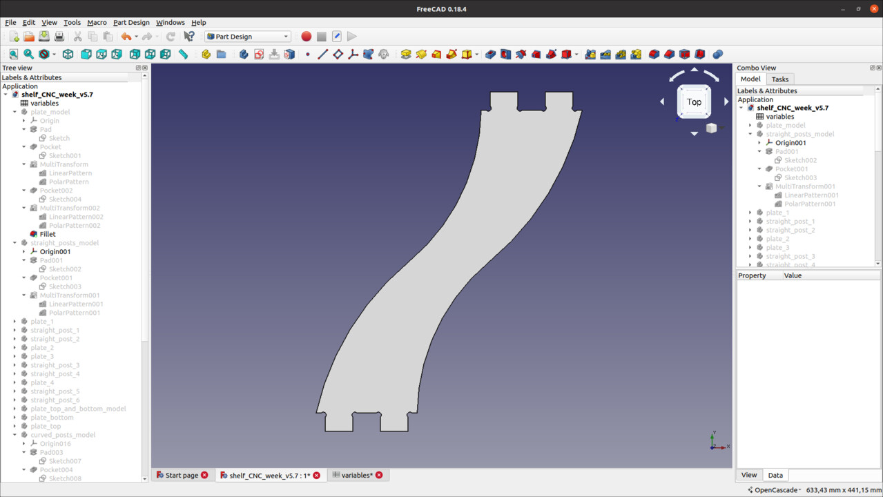 |
| Half curved shelf post sketch - Freecad | Fully curved shelf post model - Freecad |
This project idea was interesting as it required me to add dog bones in my design. Those are necessary to make it possible for the circular end mill tool to cut internal square shapes. As for designing those dog bones, I recommend reading this section on Rémy Ducros’s FabAcademy website.
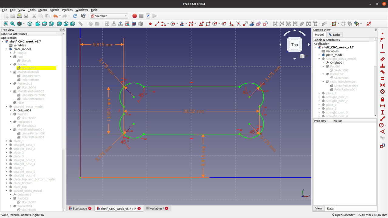 |
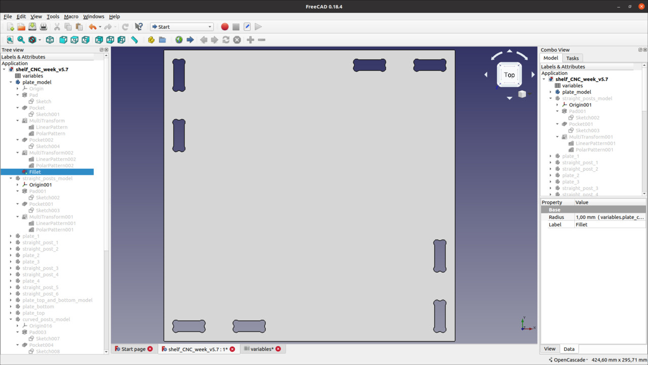 |
| Dog bone sketch design - Freecad | Dog bone cuts in the shelf plates - Freecad |
It seems that I could have integrated the dog bones using the “Path” workbench in Freecad, but I have not investigated much on this workbench by lack of time.
Preparation and cutting
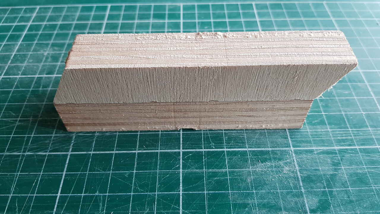
For realizing the parts presented in this section, I have used beechwood plates of the following dimensions : 610x460x20mm. As for the end-mill, I used the 1/4” Carbide 201.
Before starting to cut my large pieces of wood I have performed some clearance tests to make sure to find the appropriate parameters for my finger joints. First test was based on holes of the material thickness dimension. Each hole was presenting a difference clearance though.
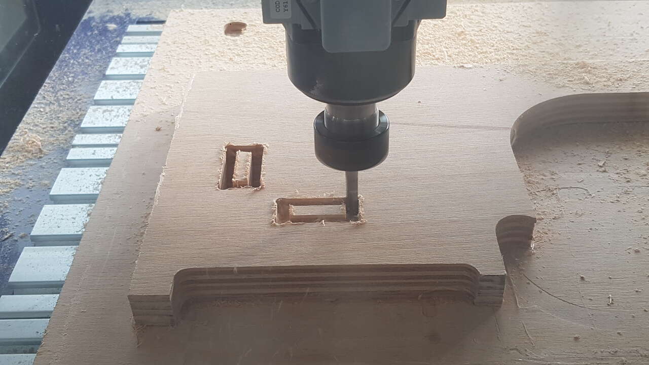 |
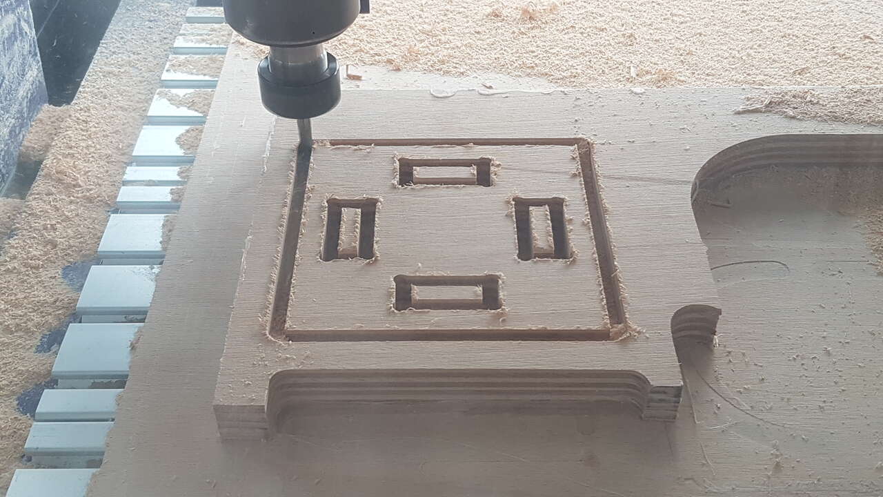 |
| Clearance test - holes cutting | Clearance test - cutout |
The results are shown in the video below :
This gave me a good idea of the clearance I needed to consider in my design. As I wanted the exterior side of my shelf posts to be aligned with the plates exterior, I performed a second test with this time holes dimensions half of the material thickness, and also with 2 notches so that it limits the post twisting around the vertical axis.
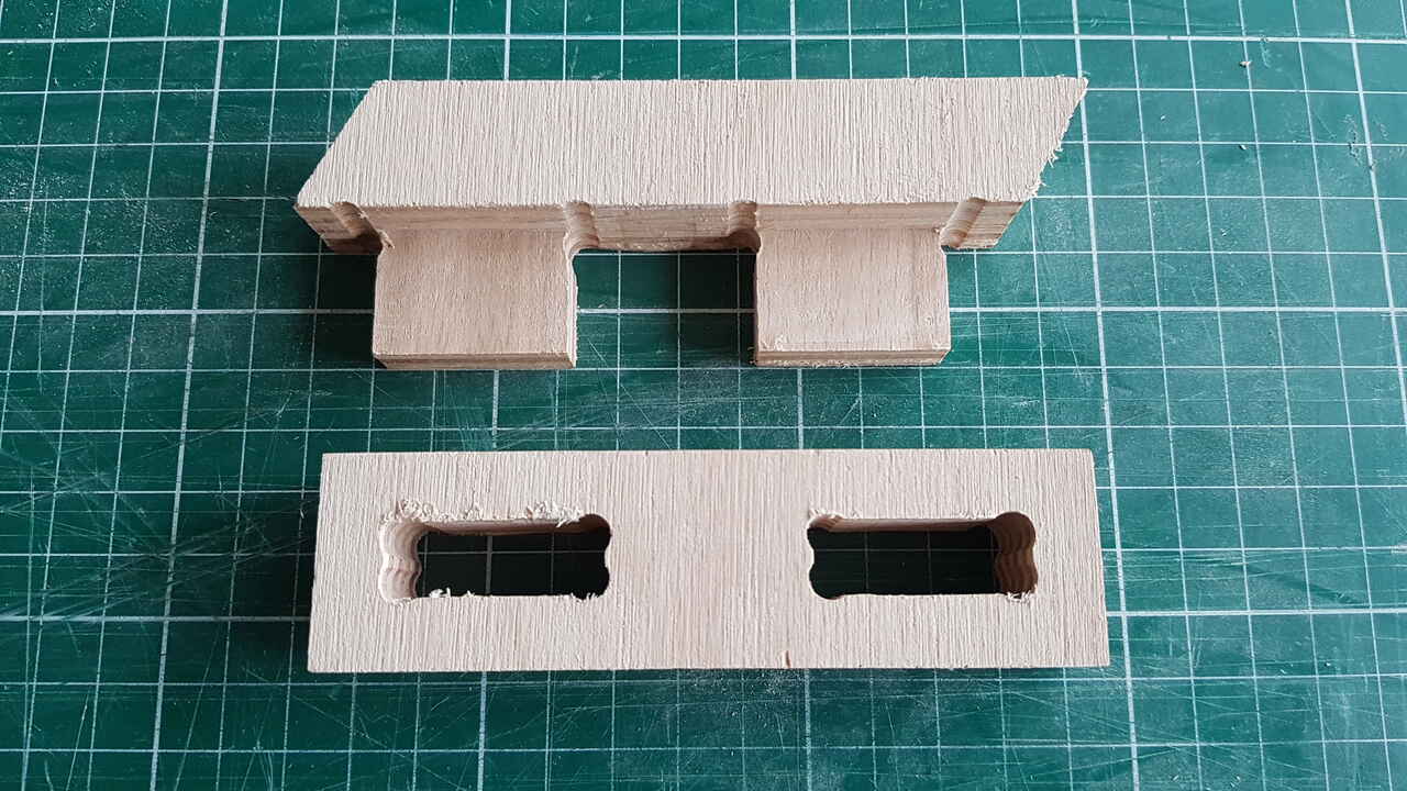 |
 |
| Clearance test similar to final design - Split parts | Clearance test similar to final design - Assembly |
I was then ready to mill the real parts for my shelf. It took me 3 full plates of 610x460x20mm, with 2 different jobs. Indeed I arranged myself so that one job could be repeated twice.
1 - Exported from Freecad all the parts I wanted to cut with the dimensions desired in .svg format.
Then I prepared my jobs for the CNC machine using VCarve v8.5 (which is not the most recent version though but the one installed in my lab computer). And I will now present all the different steps to be followed in this software before the actual job can be executed.
2 - Set the material properties (dimensions, thickness, origin, etc) :
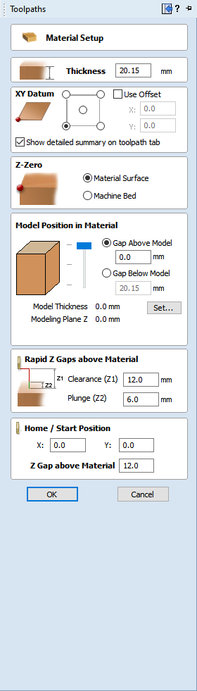
Material configuration - VCarve
3 - Selected the cutting tool :
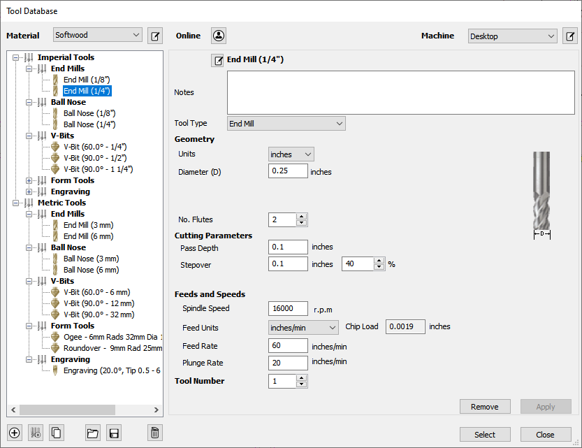
Tool selection and configuration - VCarve
Note : This screenshot does not correspond to the actual tool and settings that I have used, but it is the most similar one that I found in VCarve database when righting this documentation at home.
The settings I used were the following :
| Parameters | Values |
|---|---|
| Diameter | 1/4” |
| Pass depth | 0.06” |
| Stepover | 0.09” |
| Spindle speed | 12 000 rpm |
| Feed rate | 280 inches/min |
| Plunge rate | 120 inches/min |
4 - Positioned the parts to be cut in the 2D view, which action is also known as nesting :
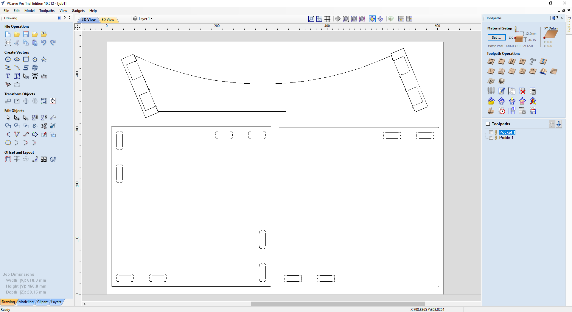
2D assembly (job 1) - VCarve
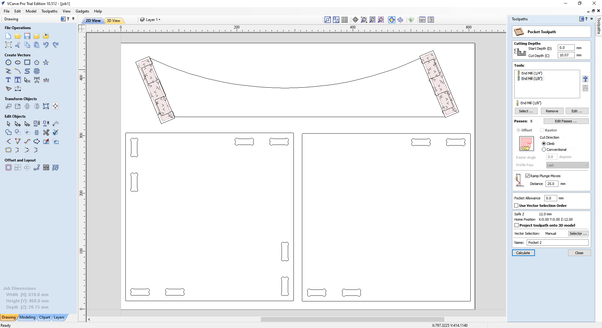
5 - Created the milling operations to be performed. In my case for both of my jobs I used pocketing and cutout operations.
Pocket configuration (job 1) - VCarve
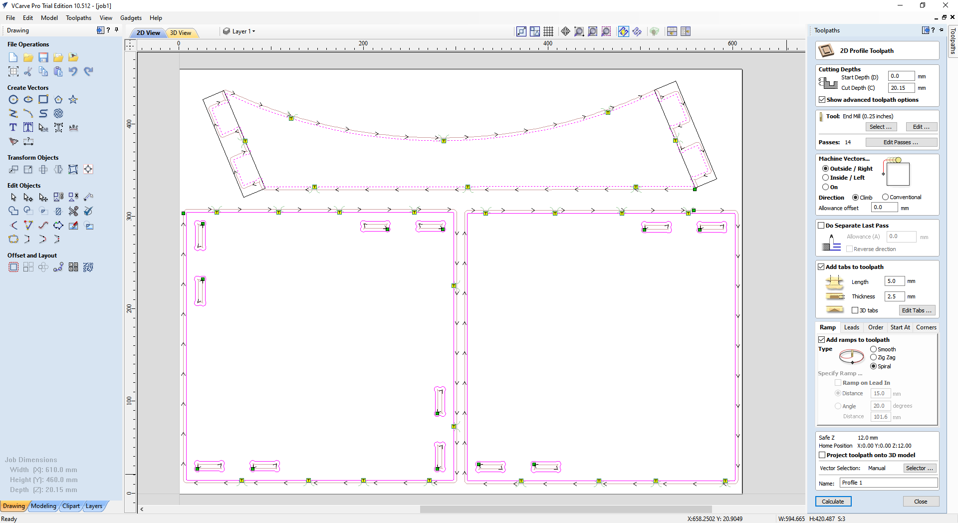
Cutout configuration (job 1) - VCarve
The yellow squares on the image above represent tabs, which have been positioned manually, and that permits to hold every part of the material in place throughout the whole milling operation.
Note: For creating a tool path that needs to cutout a frame, and inside holes, set the cut to “outside edge” and the software will automatically understand that it needs to cut outside the line for the external part, and inside the line for the inner part.
6 - Checked that the toolpath preview was corresponding to the expected operation, this step is very important as it permits to avoid mistakes that could have severe consequences if the milling operation was to be performed.
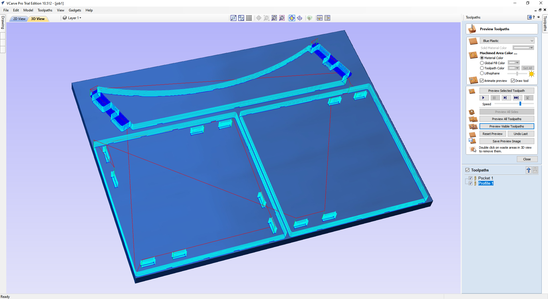 |
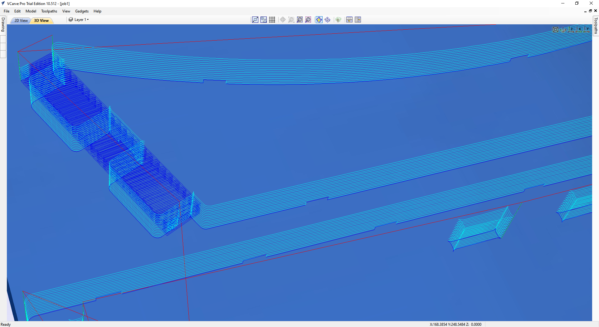 |
| Toolpath preview (job 1) - VCarve | Toolpath preview zoomed in (job 1) - VCarve |
In the images above the superposition of lines that we can observe, represent the 7 (for pockets) or 14 (for cutout) successive passes that will take place at different depth in the material.
Color code for path :
- Red line = rapid move (basically a travel)
- Dark blue line = cutting path
- Light blue line = plunge
- Green line = lift up
Below short videos presenting the animated toolpath preview for both jobs that I later executed.
7 - Executed the milling operations prepared in the previous steps.
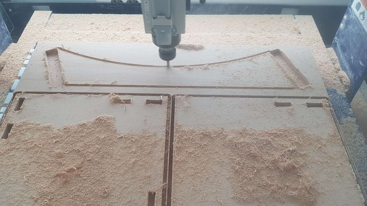
Shelf parts milling
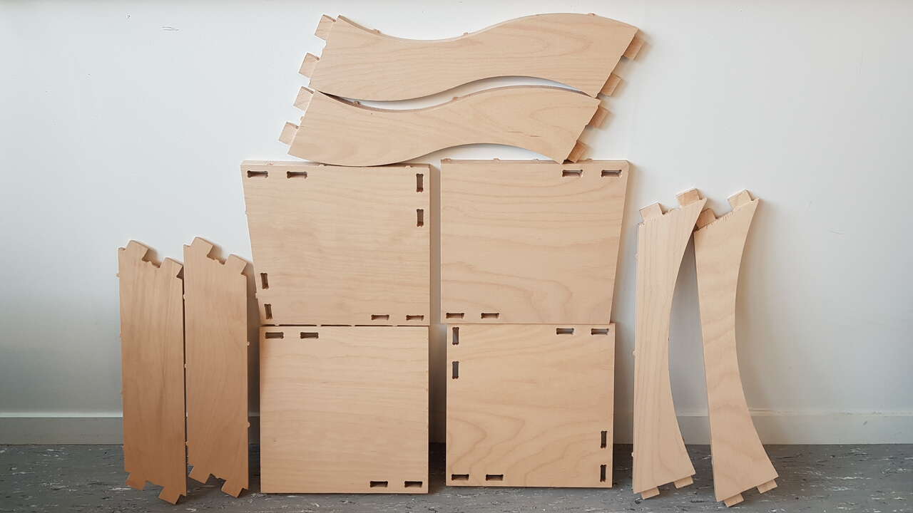
Shelf all parts
Note: tabs had not been filed yet when the picture above was shot.
Assembly
And here is the final assembly of the shelf I designed and produced !
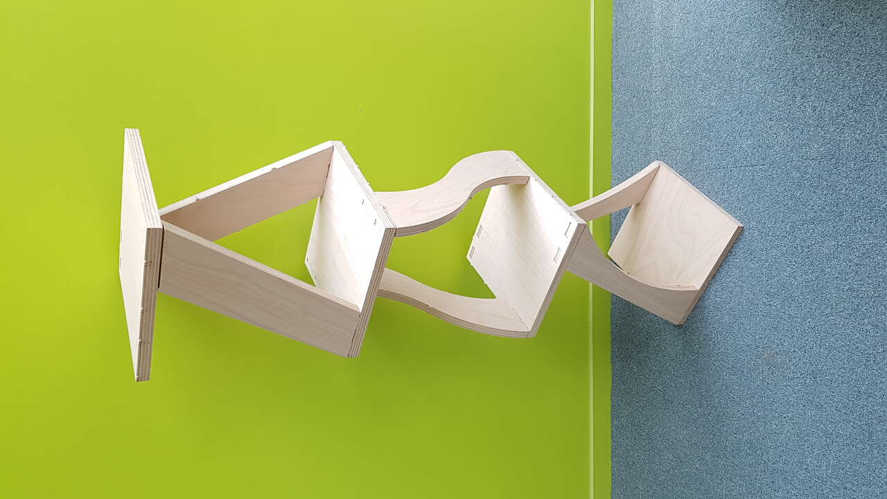
Shelf final result - CNC realization
Source files
The source files of the work presented in this week assignment are available for download here :