10. Input devices
Assignments:
Individual assignment:
- Measure something: add a sensor to a microcontroller board that you have designed and read it.
Group assignment:
- Probe an input device’s analog levels and digital signals.
Capacitive sensors
Original design
For my final project I want to integrate a puzzle that is based on the capacitive sensor technology. This week was ideal to work on this topic.
First thing for me was to read more about this technology, and this website was particularly helpful to me. It also helped me to get started with my Arduino code.
The idea for my final project is that player(s) must to touch the different cell sensors in a particular order to solve this puzzle and unlock another puzzle. The video below present what I managed to achieve (with a little extra debugging effort the days after the end of week 10) :
The software I run currently on the microprocessor does the following :
- when pressing any cell the blue LED should blink.
- when selecting successively the cell with the green wire and the one with the yellow wire, the green LED should turn ON for a short amount of time.
- when selecting two cells that are different from the sequence described above (green, then yellow), the red LED should turn ON for a short amount time.
This was quite a challenge for me as it was the first time I used a microprocessor Atmega328P.
Here are the steps I conducted for this work.
Started to perform some tests with my Arduino Uno board, using 3 simple squares of copper sheet as capacitive sensors. In the video below, I attributed one different LED to each sensor; while the sensor is touched the corresponding LED remains turned ON.
Following those tests I could improve my code and implement a solution that request touching the sensors in a particular order to solve the puzzle.
Then I laser cut and engraved a FR4 copper plate to act as the capacitive sensors.
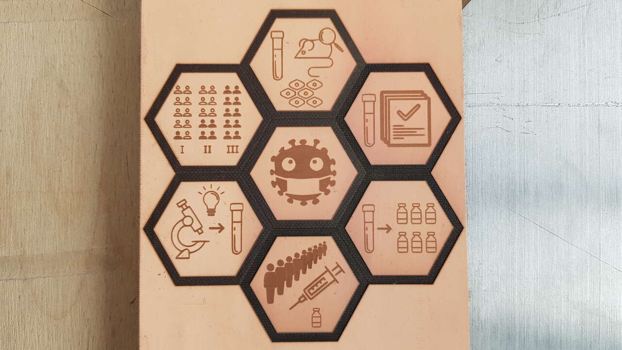
Capacitive sensors copper plate
Here are the laser parameters I used for engraving in the copper :
- type : fiber
- speed : 70%
- power : 80%
- frequency : 50
- repetition : 1
Then I confirmed with my Arduino setup that those sensors from the copper plate behaved as the copper sheet squares I used before. And it did !
I could go on with the PCB design in Eagle :
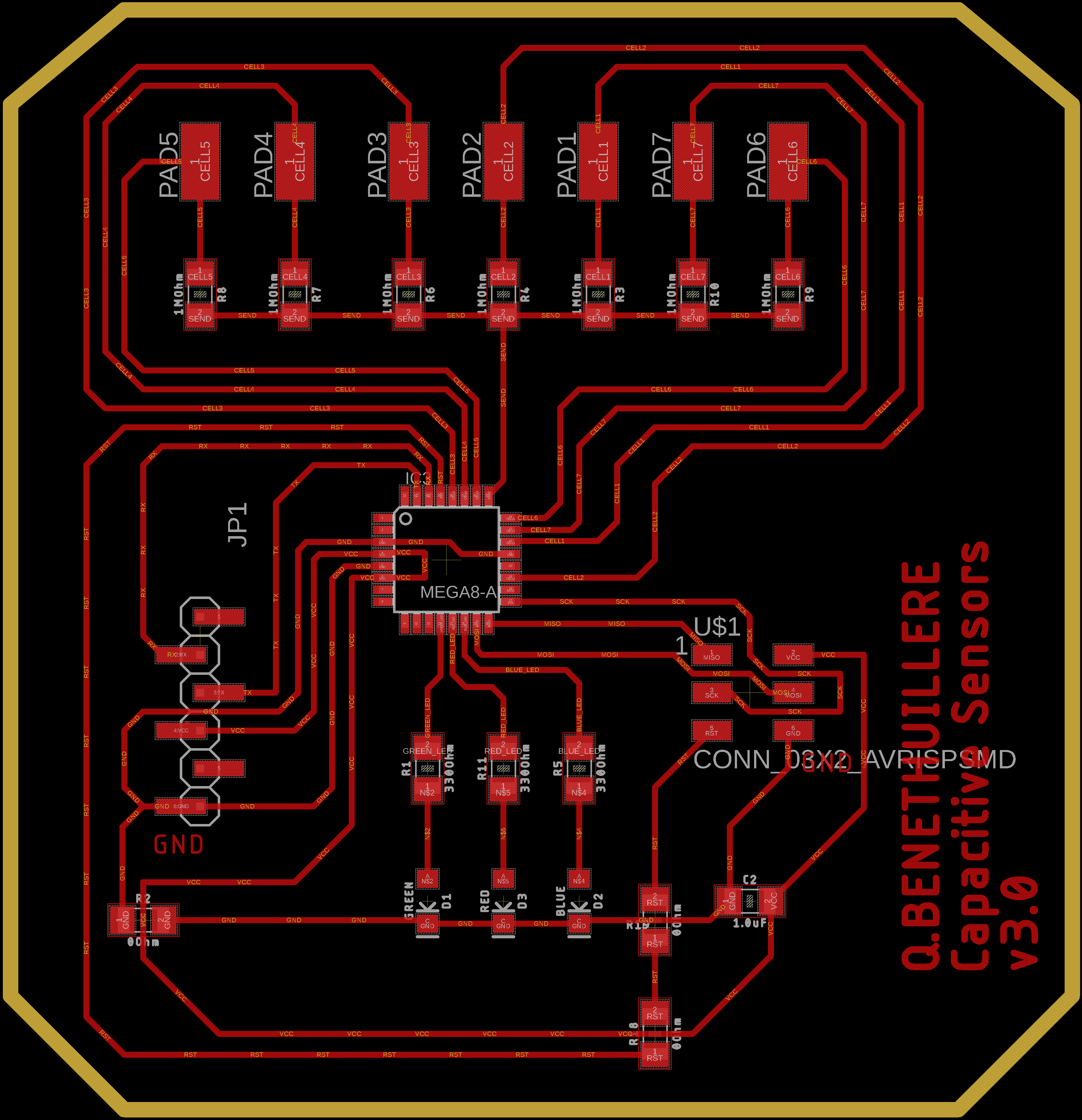
Capacitive sensors PCB board view - Eagle
Download source files.
Exported the files for laser cutting the PCB :
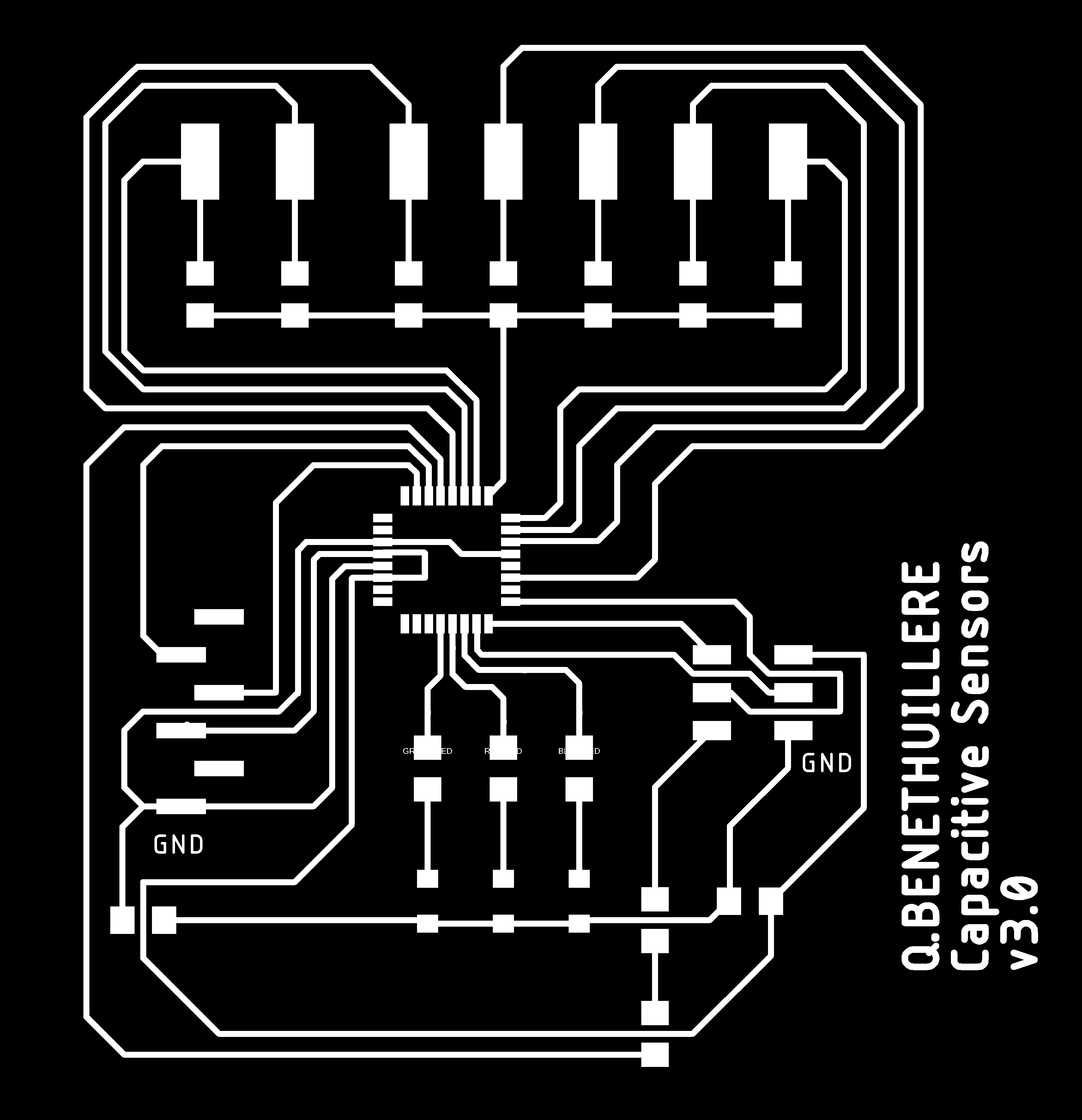 |
 |
| Capacitive sensors PCB traces extract - Eagle | Capacitive sensors PCB cutout extract - Eagle |
Laser cut the PCB, and cleant it :
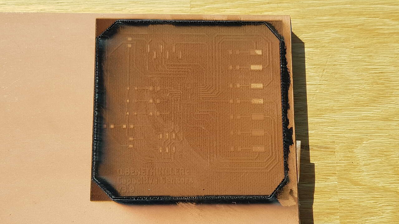 |
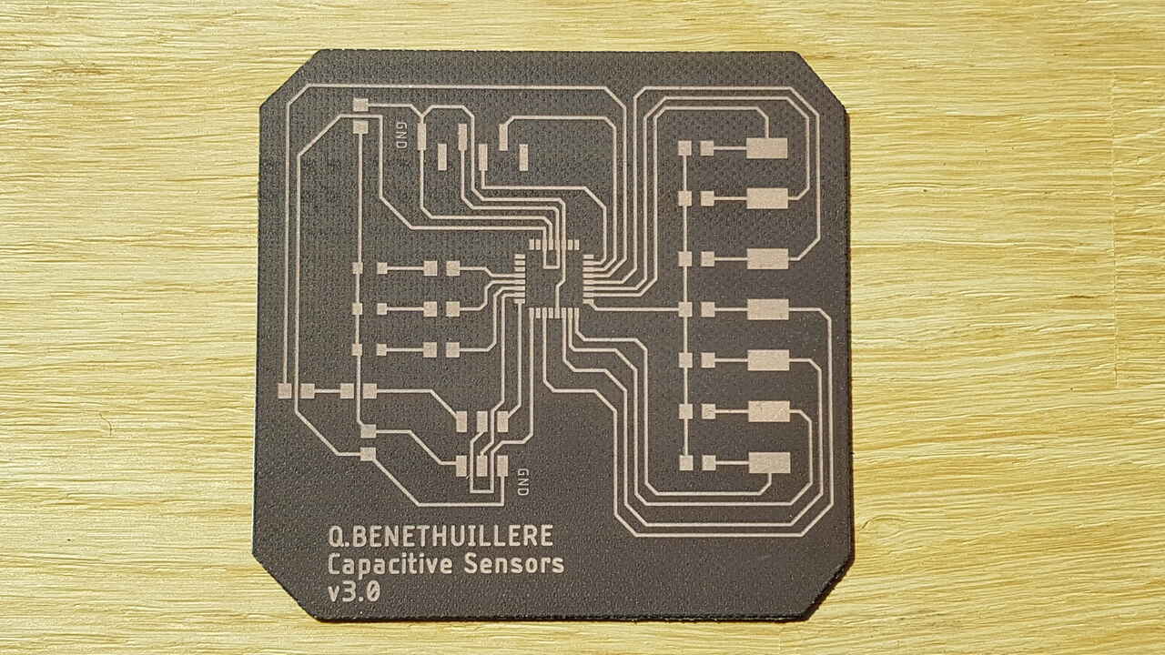 |
| PCB after laser cutting | PCB after cleaning |
After performing visual inspections I felt that everything was good, but when performing continuity tests with a multimeter I found several shorts. In the beginning I thought that the copper layer had not been removed entirely where desired with the laser cutter, but after further analysis with the electronic microscope I could see that there were some tiny copper filaments left between the microprocessor pads which are very close to one another. I easily managed to get rid of them with an exacto knife.
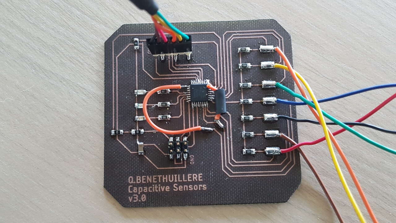
Finally I soldered the electronic components on my PCB, and established temporary connections between the PCB and the capacitive sensors.
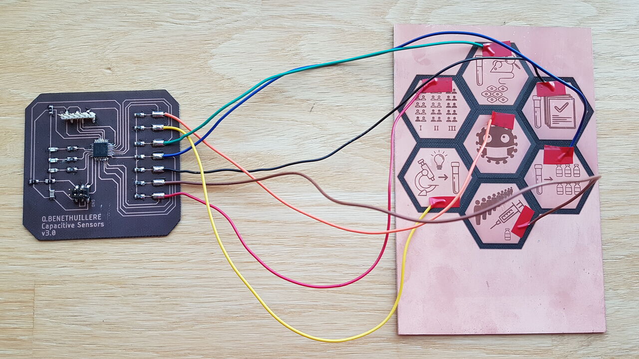
Capacitive sensors testing
Ideally I would like to solder wires on the back side of the copper plate so that no solder is visible on the front side, but after performing some tests it seems that is going to be quite difficult as the copper layer is very thin and thus breaks easily. I may need to solder wires on the front side.
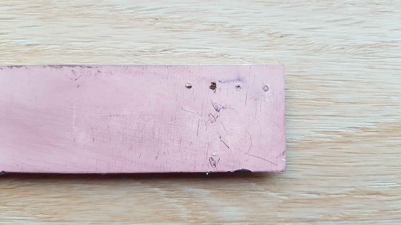 |
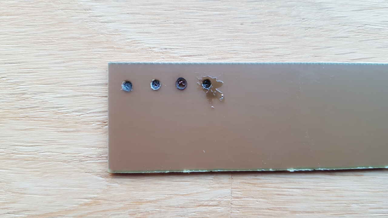 |
| PCB copper plate holes test - front view | PCB copper plate holes test - back view |
From a SW perspective, I used the Arduino IDE to write and compile my program. As for the compilor settings, I set the following :
- Board : “Arduino Pro or Pro Mini”
- Processor : “ATmega328P (5V, 16MHz)”, but I may rather use “ATmega328P (3.3V, 8MHz)” instead.
- Programmer : “USBtinyISP”
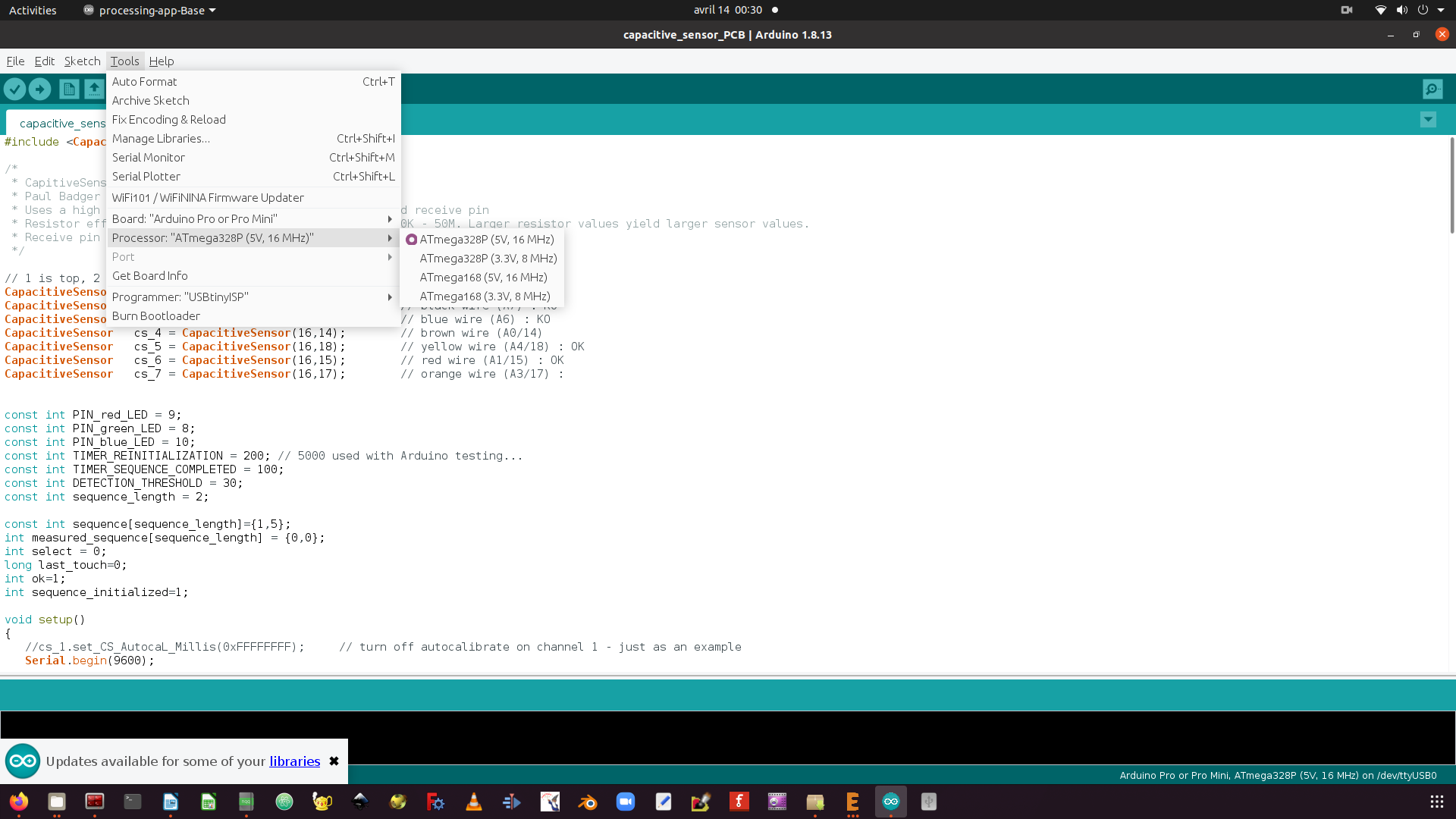
Arduino IDE settings for compiling code
Download source code. ***Note: ***
I could then flash my Atmega328P microcontroller using the FabTinyISP I made in week 04 with the following command :
avrdude -c usbtiny -p m328p -P usb:002:025 -U flash:w:capacitive_sensor_PCB.ino.eightanaloginputs.hex
Unfortunately, this fuse calculator website was not working when I needed it, so I was not able to set the fuse correctly for my Atmega328P to run at 8MHz. This definitely had an impact on the results I observed as the capacitive sensor uses time response to determine whether the sensor is touched or not. As a result the values I measured were way different than the ones I measured with my prior Arduino Uno tests. Also I did not manage that week to establish serial communication between my board and my computer. This is basically what I managed to achieve for this week on this topic, and here is a quick video of the first results obtained (which were not exactly as expected as discussed in this paragraph) :
Issues tracking and solutions
In the following days I managed to calculate the fuses I needed to fix my clock issue, and was able to set them correctly with the following command :
avrdude -c usbtiny -p m328p -P usb:002:008 -U lfuse:w:0xe2:m -U hfuse:w:0xd9:m -U efuse:w:0xff:m
Also I managed to settle my serial communication once I understood that I had wired my Rx and Tx pins the wrong way. Indeed when looking at the picture below showing the pinout of an FTDI USB to serial cable, the cable Tx pin must be connected to the Rx pin of the PCB, and the Rx pin of the cable must be connected to the Tx pin of the PCB.
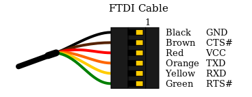
FTDI USB to serial cable - pinout
Once the serial communication established through the Arduino IDE serial monitor, I was able to analyze the outputs I obtained from the various capacitive sensors. And this permitted to confirm that 2 sensors were not responding as expected. In the screenshot below, where each column represents the value returned by a capactitive sensor over time, one can notice that 2 sensors always return “-1”.
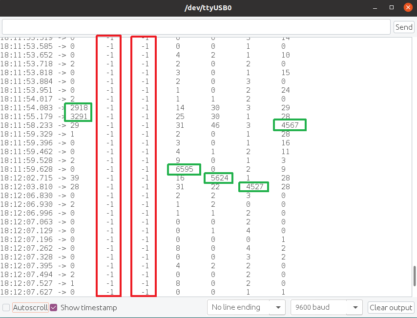
Serial communication - capacitive sensors output
After analyzing the Atmega 328P pinout diagram presented hereunder I concluded that those sensors were not working propery because they were mapped to ANALOGIC ONLY pins (A6 and A7).
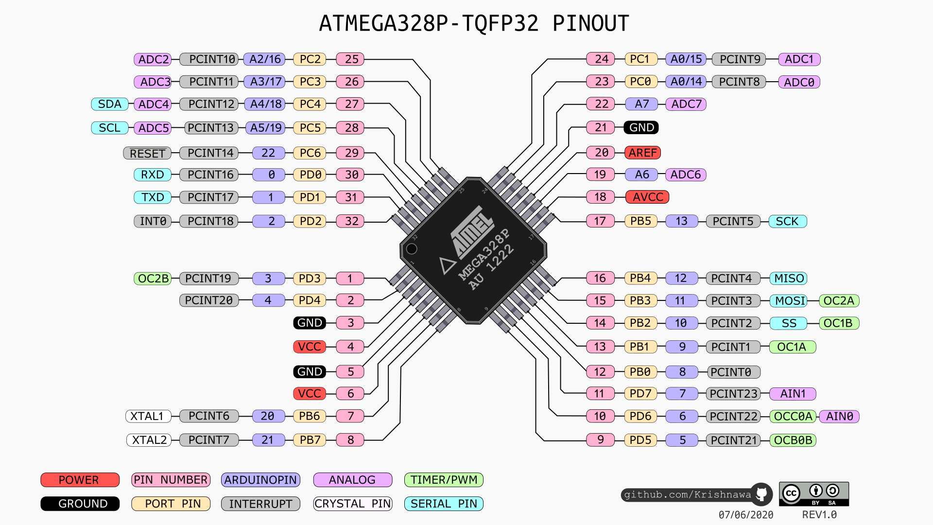
ATmega 328P - pinout
Also the serial communication analyzis allowed me to find an error in my code, a “break” instruction was not positioned at the right location.
Once all those errors identified, I could add HW patches to my PCB to remap the 2 problematic sensors to digital PIN, and I got it working all fine !
PCB with HW patches
Final testing results, this time aligned with the expected behaviour :
Various sensors testing
I started the week by testing a bunch of sensors I have at home since several years but that I have never had the opportunity to play with.
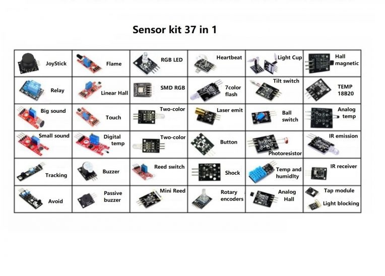
Here below are presented the sensors I have and a document that gives the function for most of them :
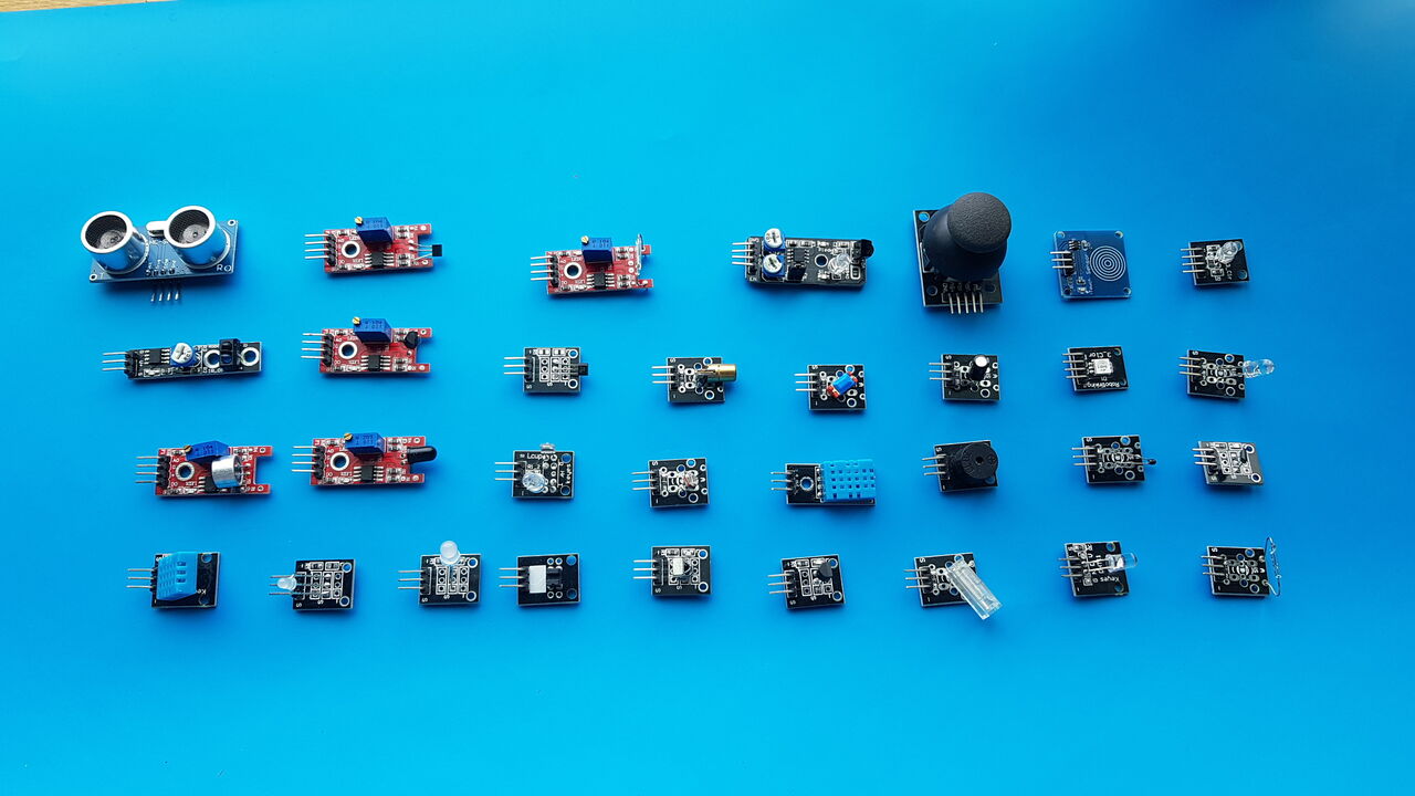
Sensors presentation
In order to test them, I mainly refered to https://arduinomodules.info/ and the Sensor Kit website. There I could find a brief description on how those sensors work, as well as short Arduino programs to test their basic functionalities. Most of the time, in order to observe the behaviour of those sensors I used the Serial Monitor or the Serial Plotter available in the Arduino IDE. Please find below screenshots of those two interesting tools when looking at the signals coming from a joystick :
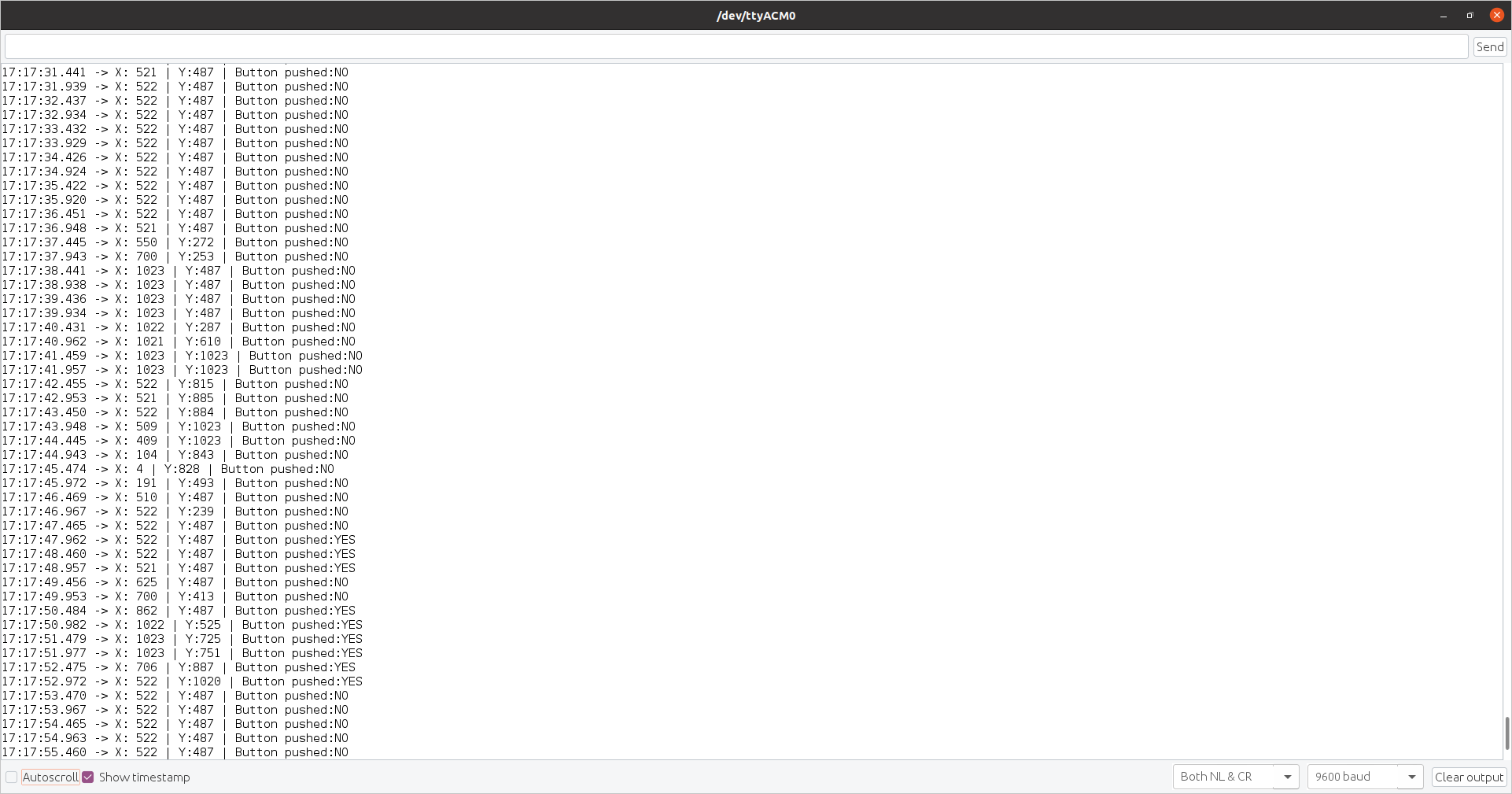
Joystick testing - Arduino IDE serial monitor
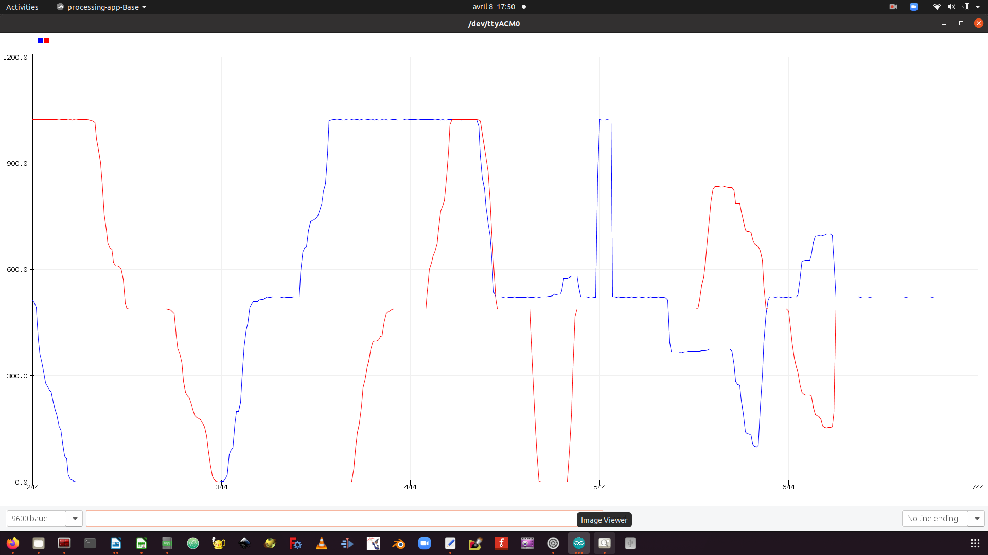
Joystick testing - Arduino IDE serial plotter
The video hereunder present the tests I performed with a joystick, an ultrasonic distance sensor, a PIR motion sensor, a touch sensor, a flame sensor, a tracking sensor, and a photoresistor.
From a technical point of view, and as one can see in the various graphs that I presented, the analogic signals are converted into a 10 bits digit by the Analog to Digital Converter, which corresponds to a number between 0 and 1023. From this value combined with the power supply voltage, it is possible to calculate the voltage given by the sensor with a simple cross product.
Group Assignment
For the group assignment we have analyzed with an oscilloscope the signals from an HC-SR04 ultrasonic distance sensor. For further information on this activity, please refer to our group page.
Source files
The source files of the work presented in this week assignment are available for download here :
- Eagle design
- Capacitive sensors first Arduino test
- Final program : capacitive_sensor_PCB.ino / capacitive_sensor_PCB.hex