11. Molding and casting
Assignments:
Individual assignments:
- Design a mold around the stock and tooling that you’ll be using.
- Mill it (rough cut + (at least) three-axis finish cut).
- Use it to cast parts.
Group assignments:
- Review the safety data sheets for each of your molding and casting materials.
- Make and compare test casts with each of them.
Group Assignments
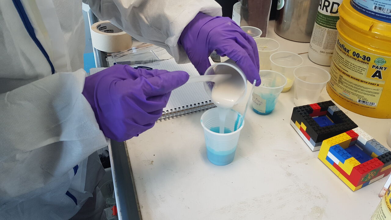
With my colleagues Selena and Ambroise we started the week by reviewing the datasheets of the different molding and casting materials available at fablab Digiscope. Following this, we decided to prepare test casts of each material to compare the results obtained, to get used to the preparation process, and to experiment with the different curing times of the materials.
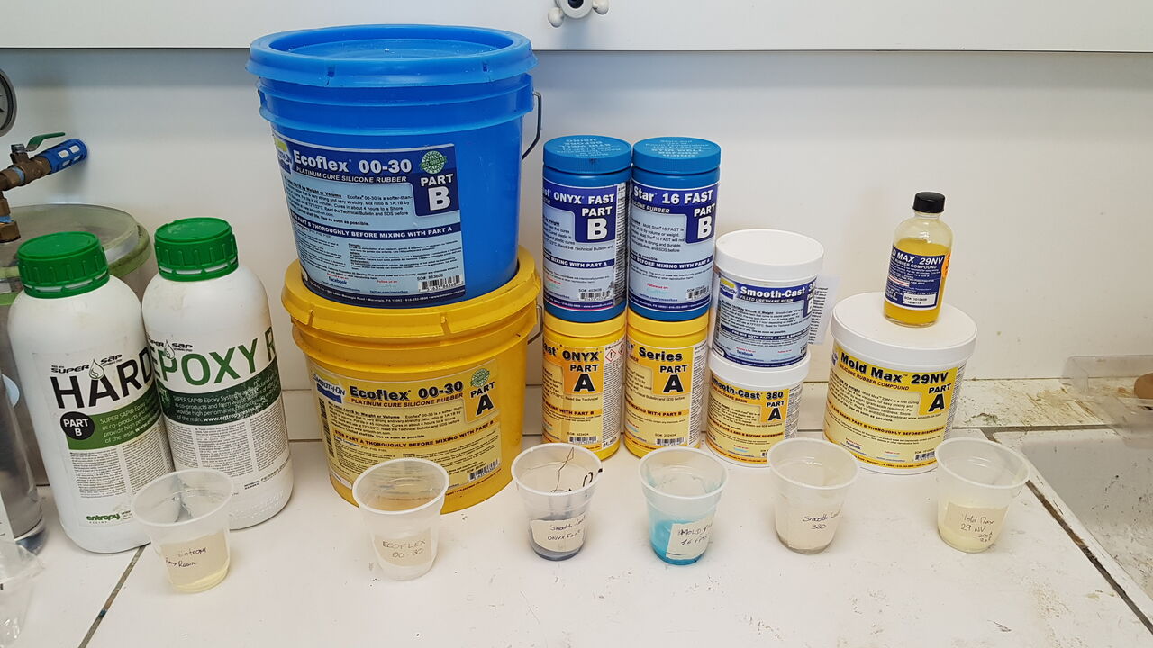
Test casts materials
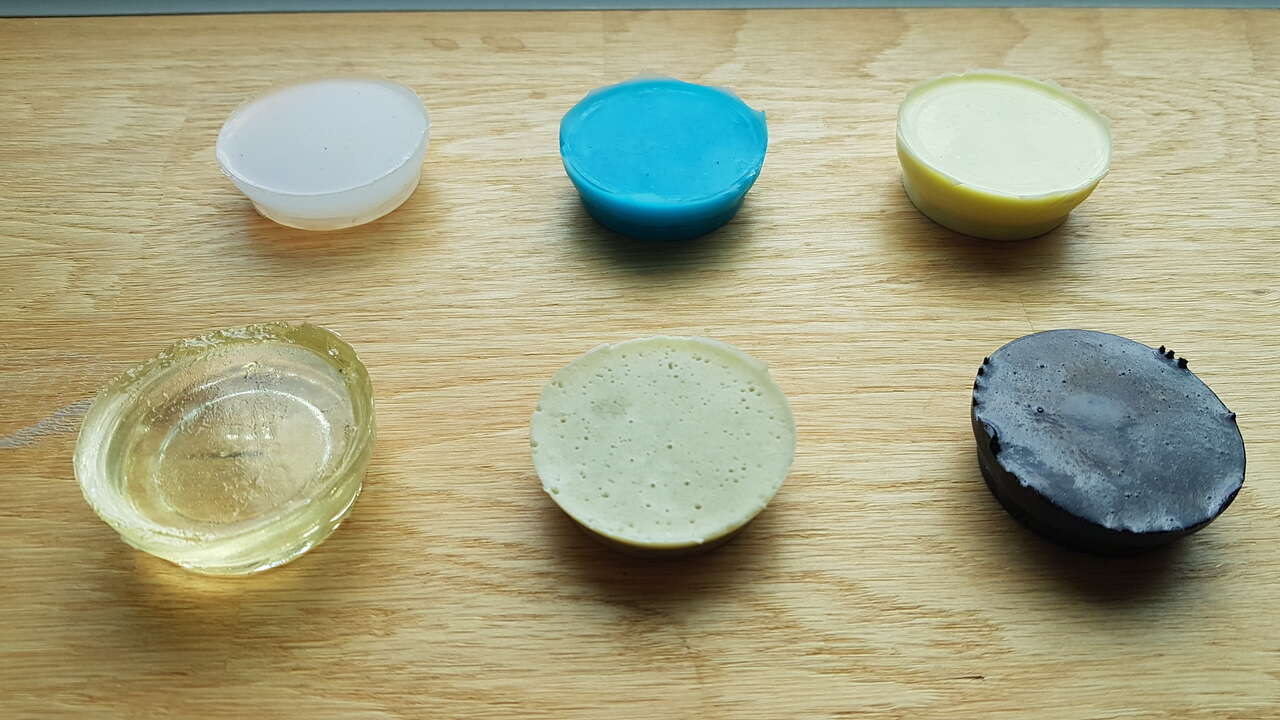
Test casts results
Our work is presented in more details in our group page.
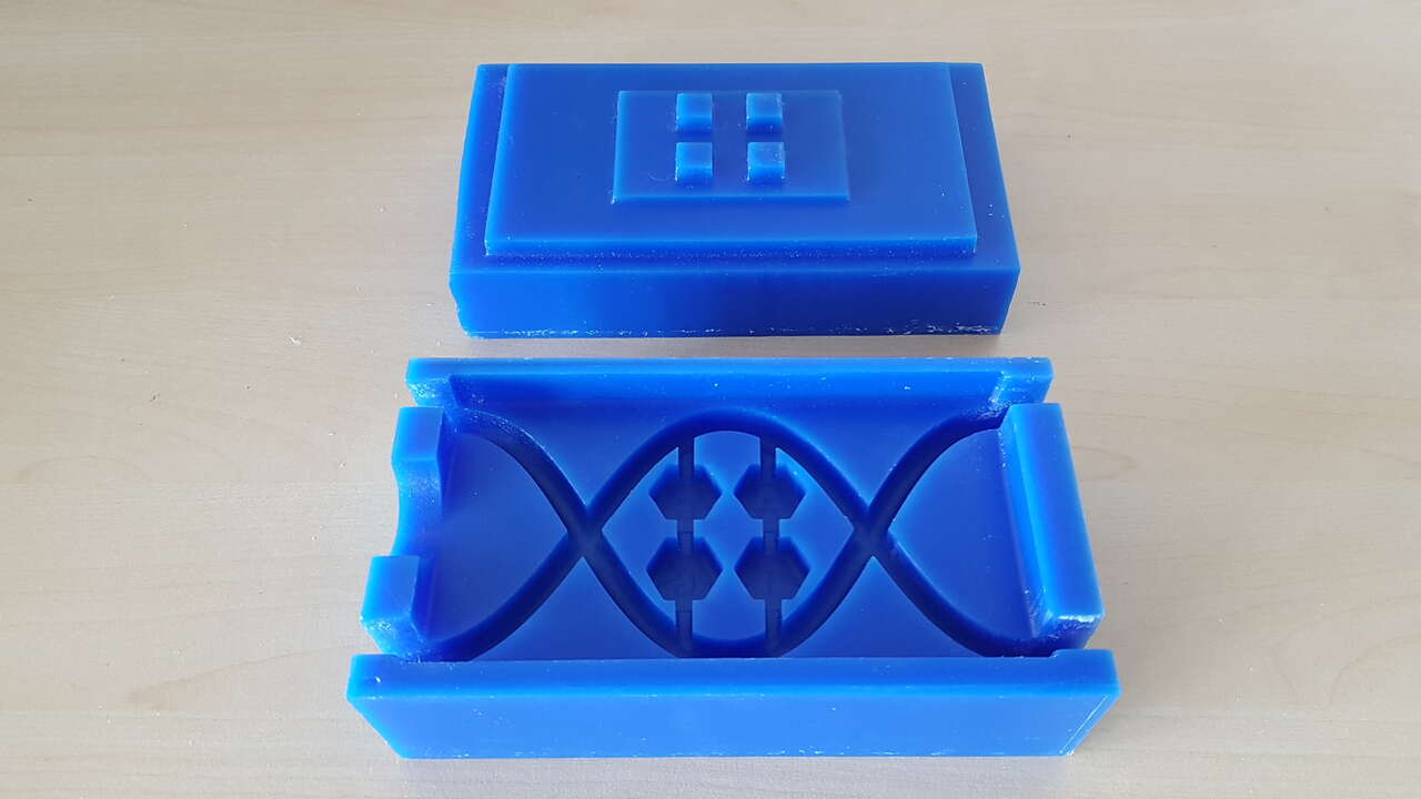
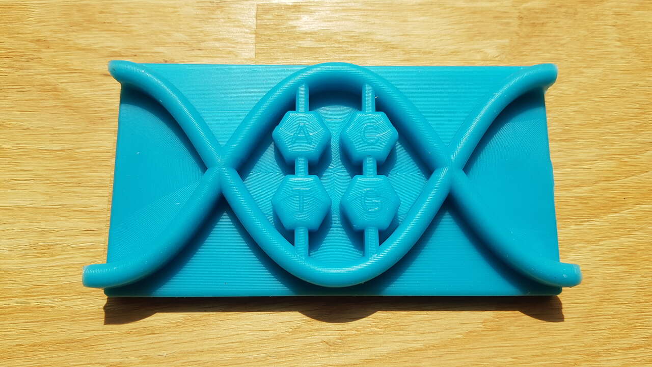
Silicone DNA keypad
I decided to take advantage of this week to design and cast a silicone DNA keypad for my final project puzzle box. The whole idea is then to integrate 4 push buttons in this keypad for the mechanism presented in the below video.
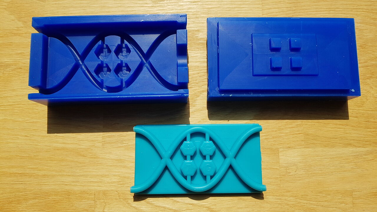
Silicone DNA keypad and molds
Note: In the video a button is used to allow user to erase the last entry, but I might not implement this function in my final project.
Summary video
For a nice overview of this week’s work, have a look at the summary video hereunder. The following sections will then give more details about my realization.
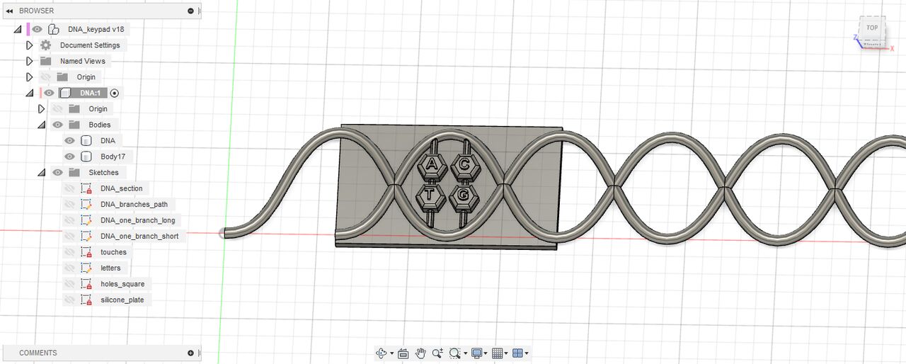
3D design
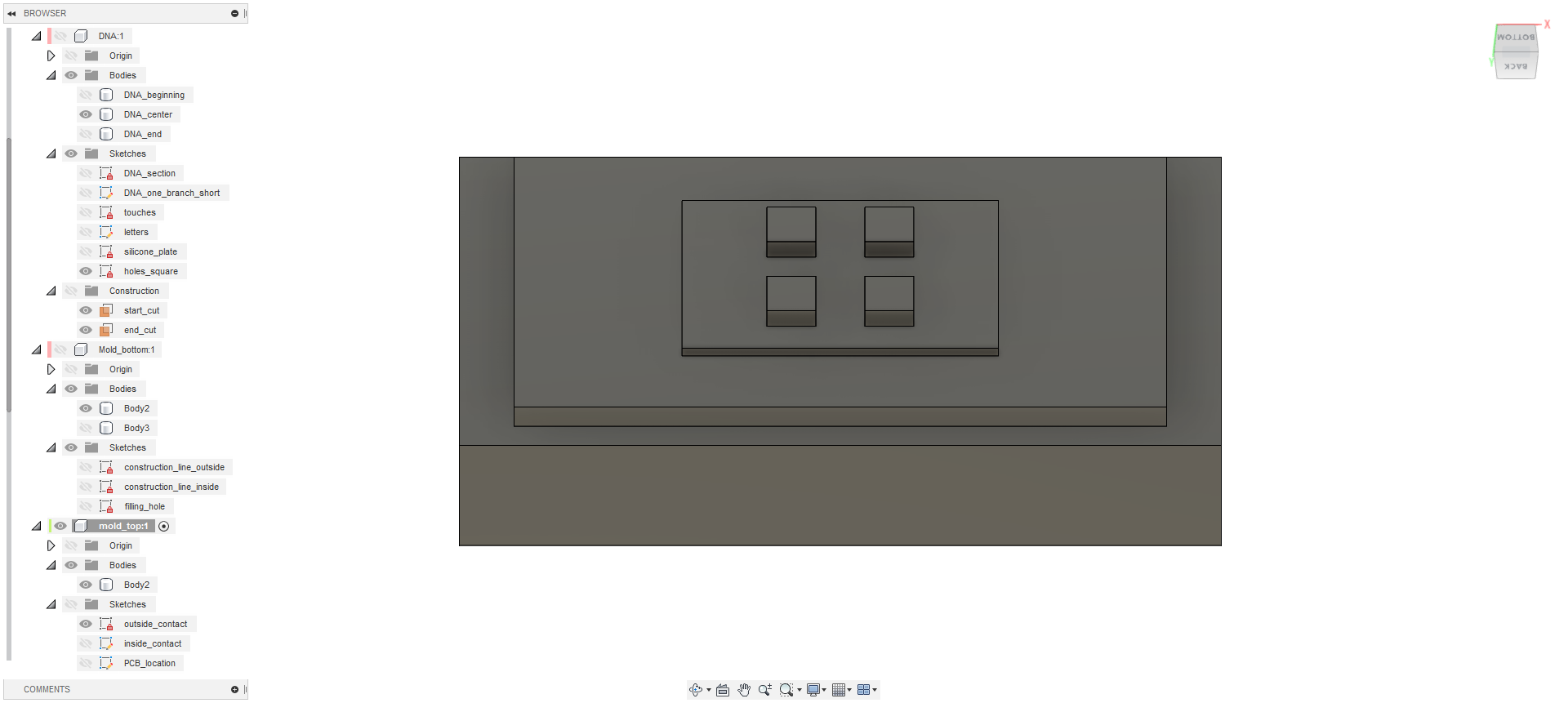
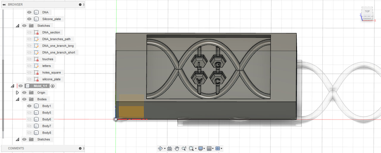
I performed all the design work in Fusion 360. Herebelow is presented a series of screenshots revealing the design steps to obtain the final object and the intermediate molds to cast it.
The first challenge was to design the sinusoidal shape. Unfortunately it is not possible to natively use equations in the design workbench of Fusion 360. I have read on the internet that this could be done using an API, but after a quick unsuccessful try I decided to draw it myself with well thought constraints.
DNA sinusoidal shape design - Fusion 360
I have voluntarily designed a longer DNA sinusoidal shape than the one needed for this molding and casting assignment as I may use it later on for decorating my puzzle box.
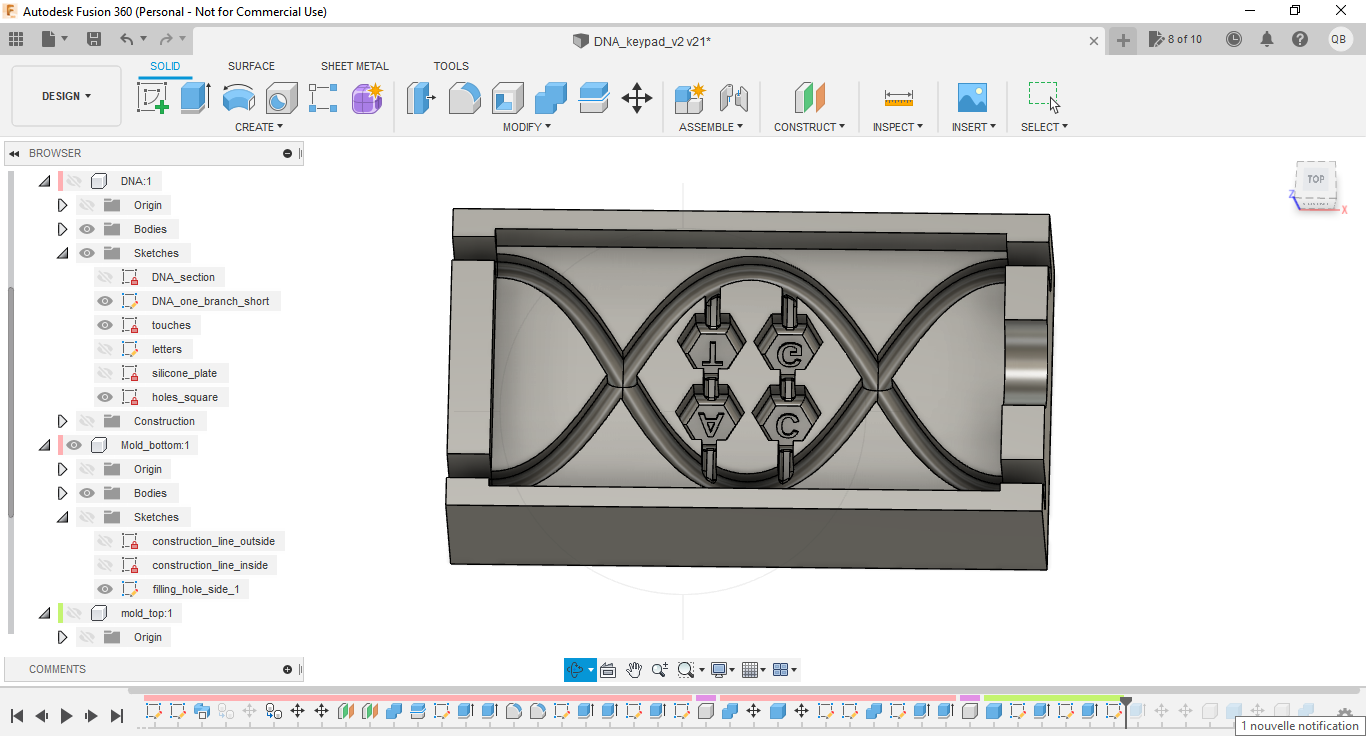
After a few additional operations, I obtained the final object design :
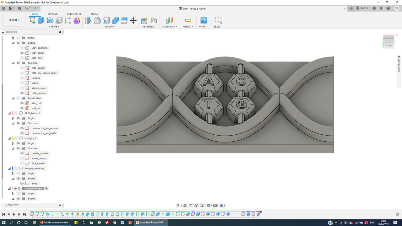 |
 |
| DNA keypad - front view - Fusion 360 | DNA keypad - back view - Fusion 360 |
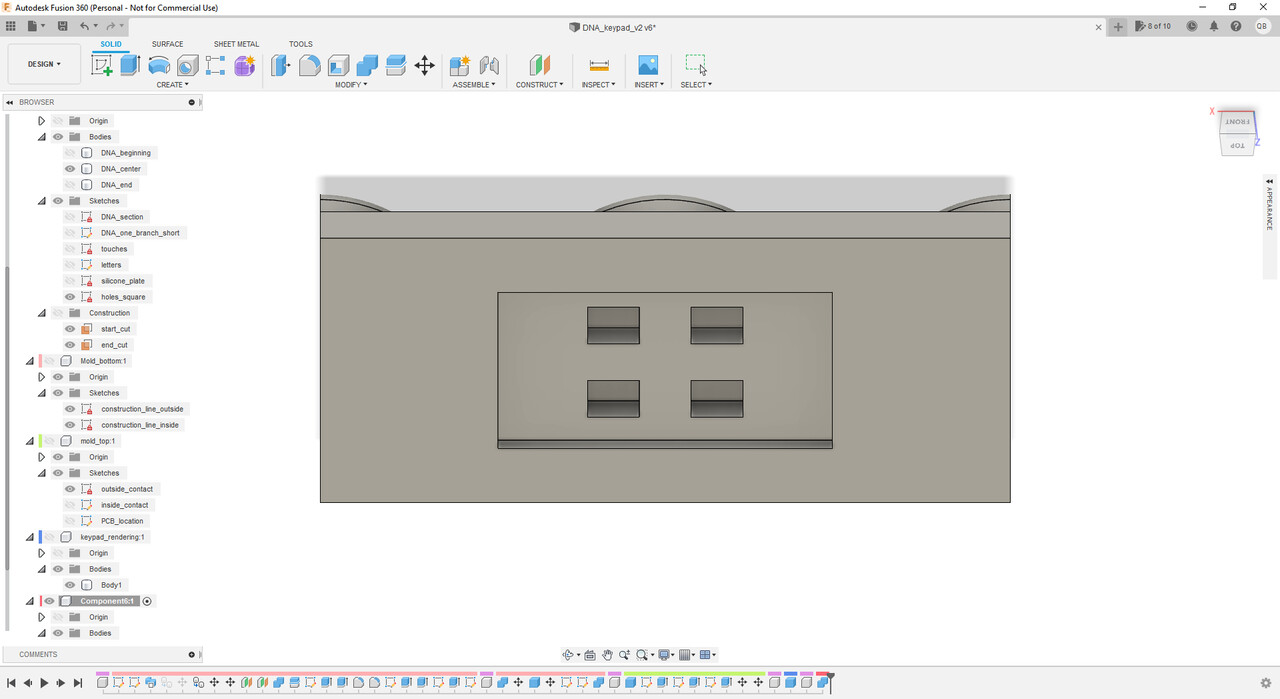
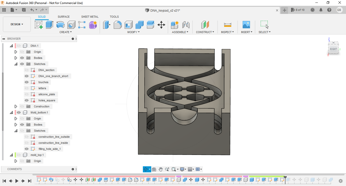
Molds shapes were then computed by applying combined cut operations :
Mold top part - Fusion 360
Mold bottom part - Fusion 360
Finally, I designed filling and vent holes for casting. I chose to create 2 filling holes along the DNA veins, and a center hole to allow air exhaust while casting. Also as I created 2 holes along the DNA vein on the opposite side in order to make sure that the silicone was going all the way through while casting; those last 2 holes were of course obstructed with tape for the casting operation.
 |
 |
| Mold bottom part with holes - front view - Fusion 360 | Mold bottom part with holes - side view - Fusion 360 |
Molds CNC machining
Preparing files
Once the molds design ready, I could create the files for the CNC milling operations, still using Fusion 360. For the CNC assignment week 07 I had used VCarve Pro software for this operation, but at that time I used to design my parts with FreeCAD software.
1 - Open the “Manufacture” workbench.
2 - Create a new setup :
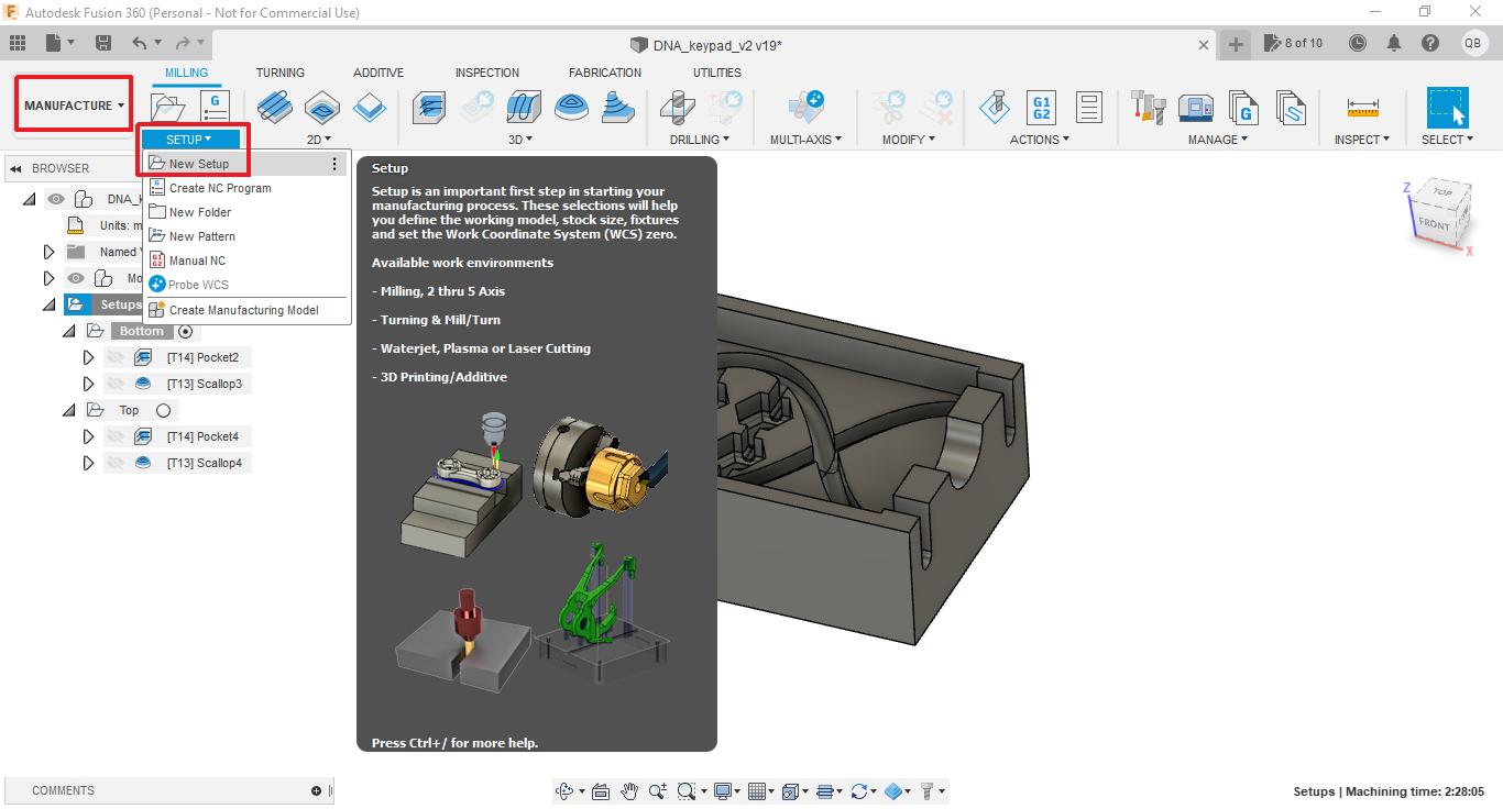
Create new setup - Fusion 360
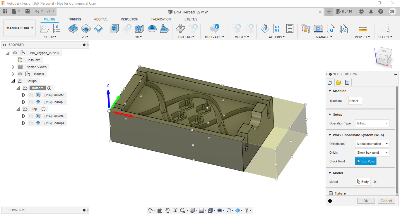
3 - Edit setup (right click on the setup -> “Edit”), select the desired body, adjust coordinate system (set the origin to the top of the material) and stock dimensions :
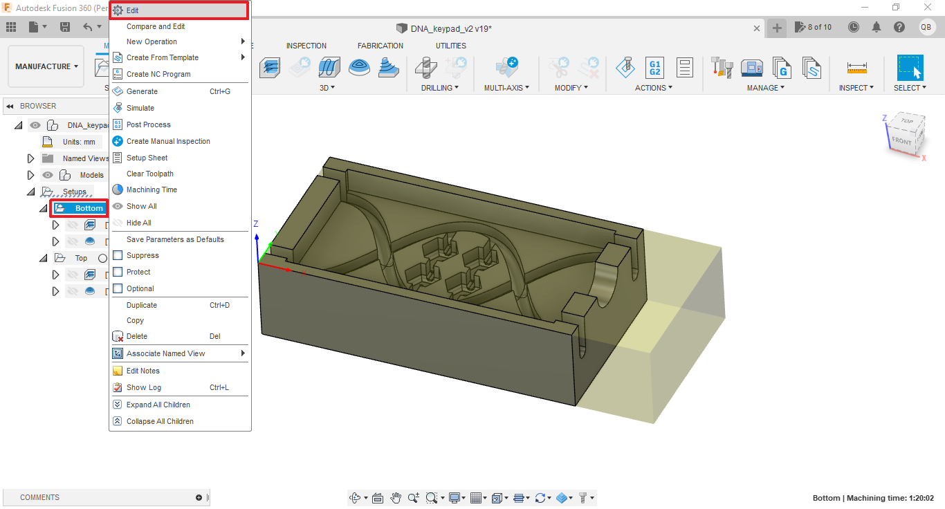
Edit setup - Fusion 360
 |
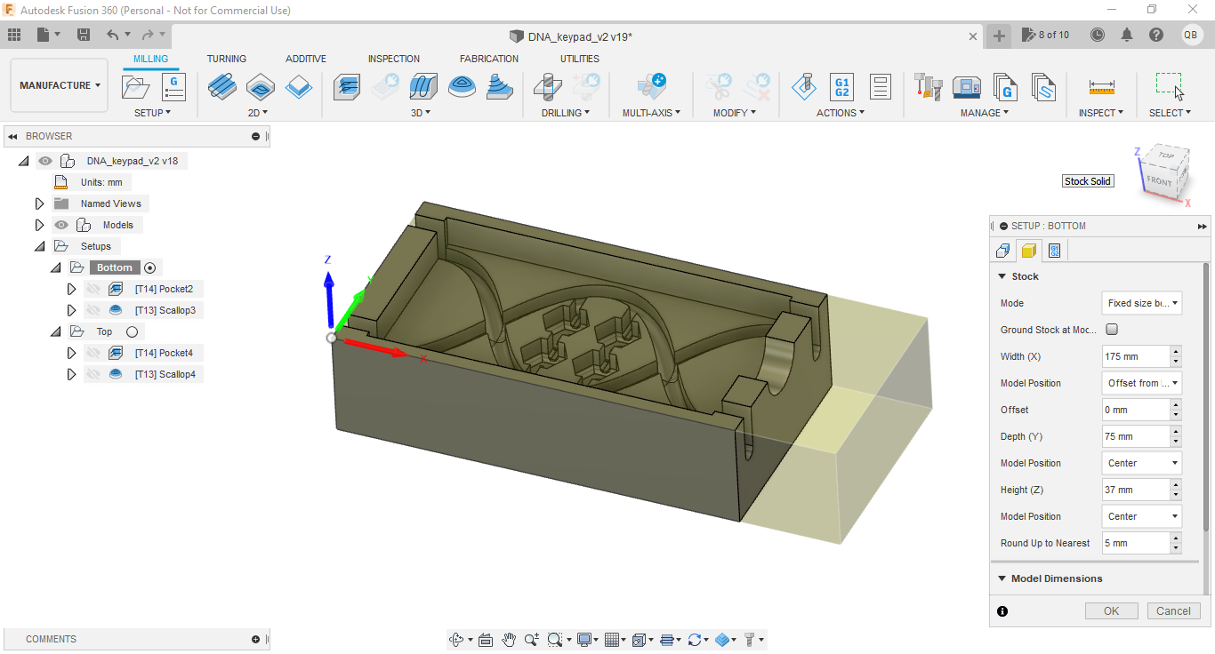 |
| Setup coordinate system - Fusion 360 | Setup stock - Fusion 360 |
4 - Create 3D rough cut operation (called “Pocket Clearing”) :
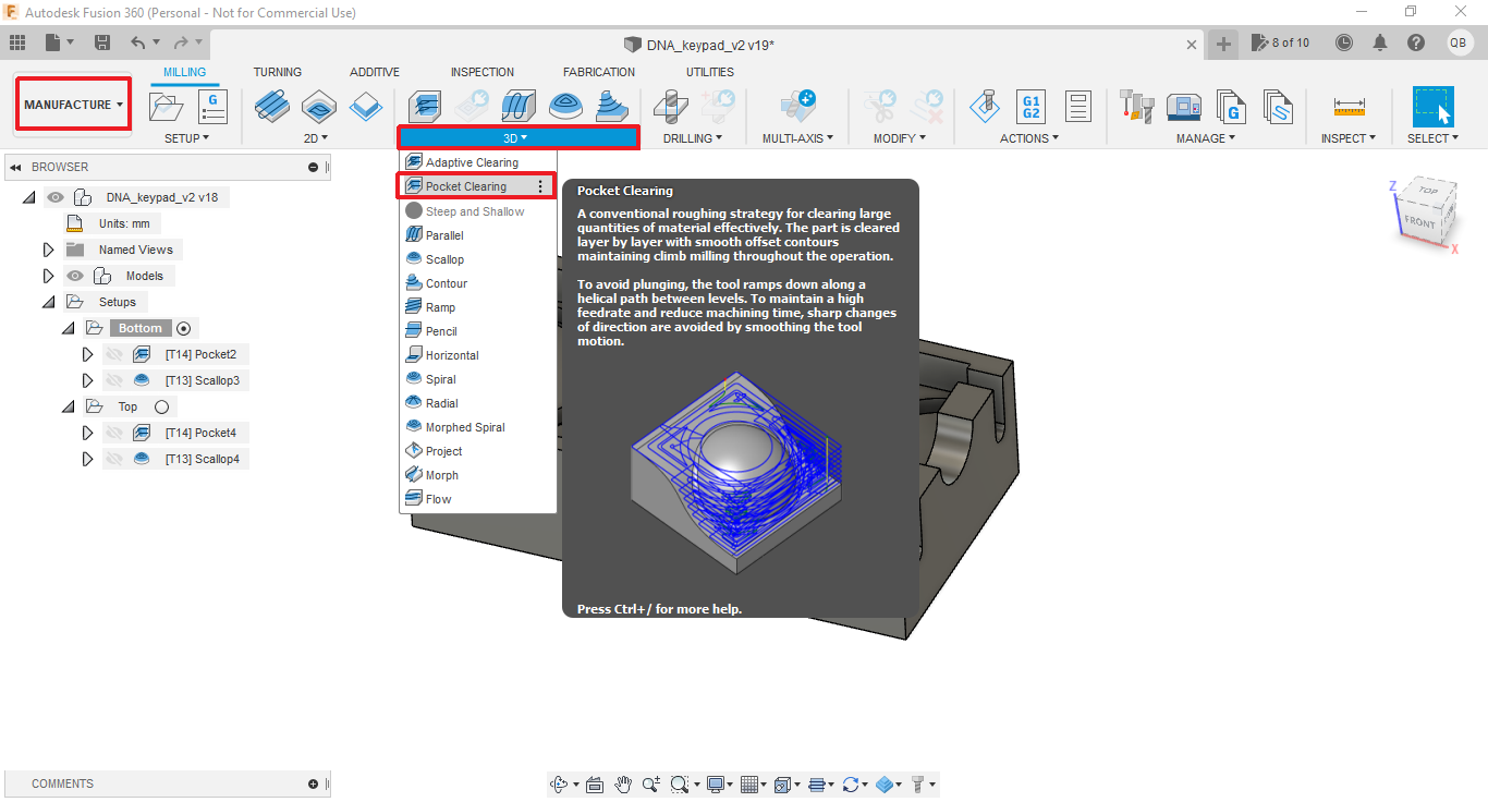
Create 3D rough cut operation - Fusion 360
5 - Configurate rough cut parameters (tool, clearance height, step over, stock to leave, ramp type, etc).
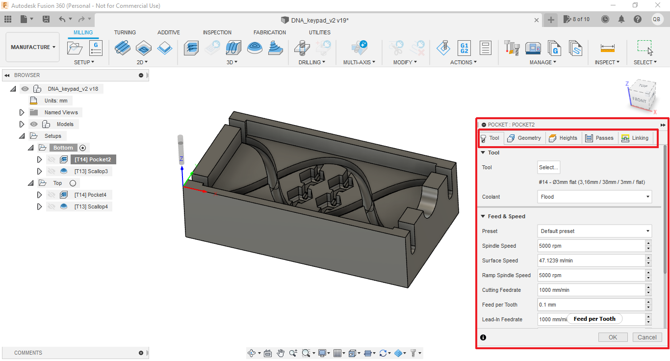
Configurate 3D rough cut operation - Fusion 360
Note : for some reason selecting “helix” for the ramp type may raise errors during the cut simulation, in this case rather use “plunge”.
6 - Simulate cut operation (right click on the cut operation -> “Simulate”) :
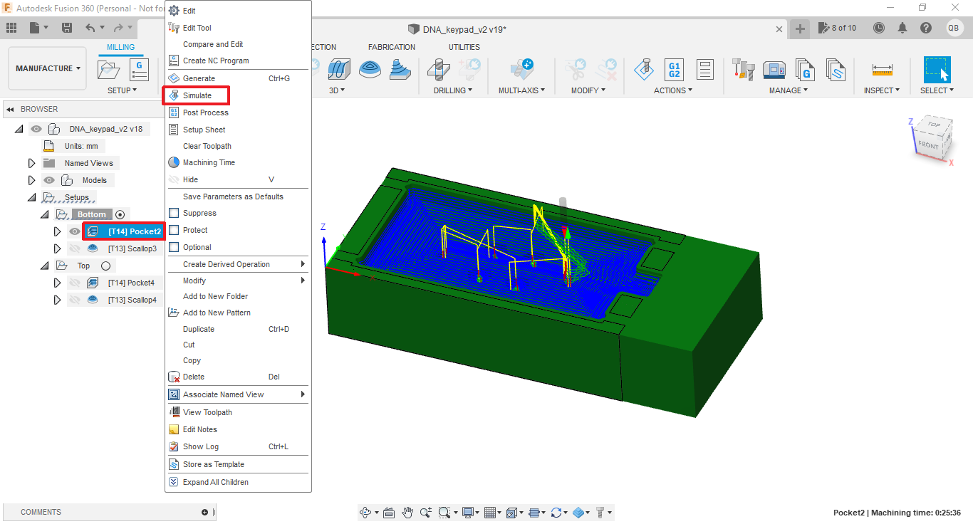
Simulate 3D rough cut operation - Fusion 360
7 - If no error or warning is raised and that you are happy with the simulation results, go on with next step, otherwise go back to step 5 and readjust parameters.
8 - Create 3D finish cut operation (called “Scallop”) :
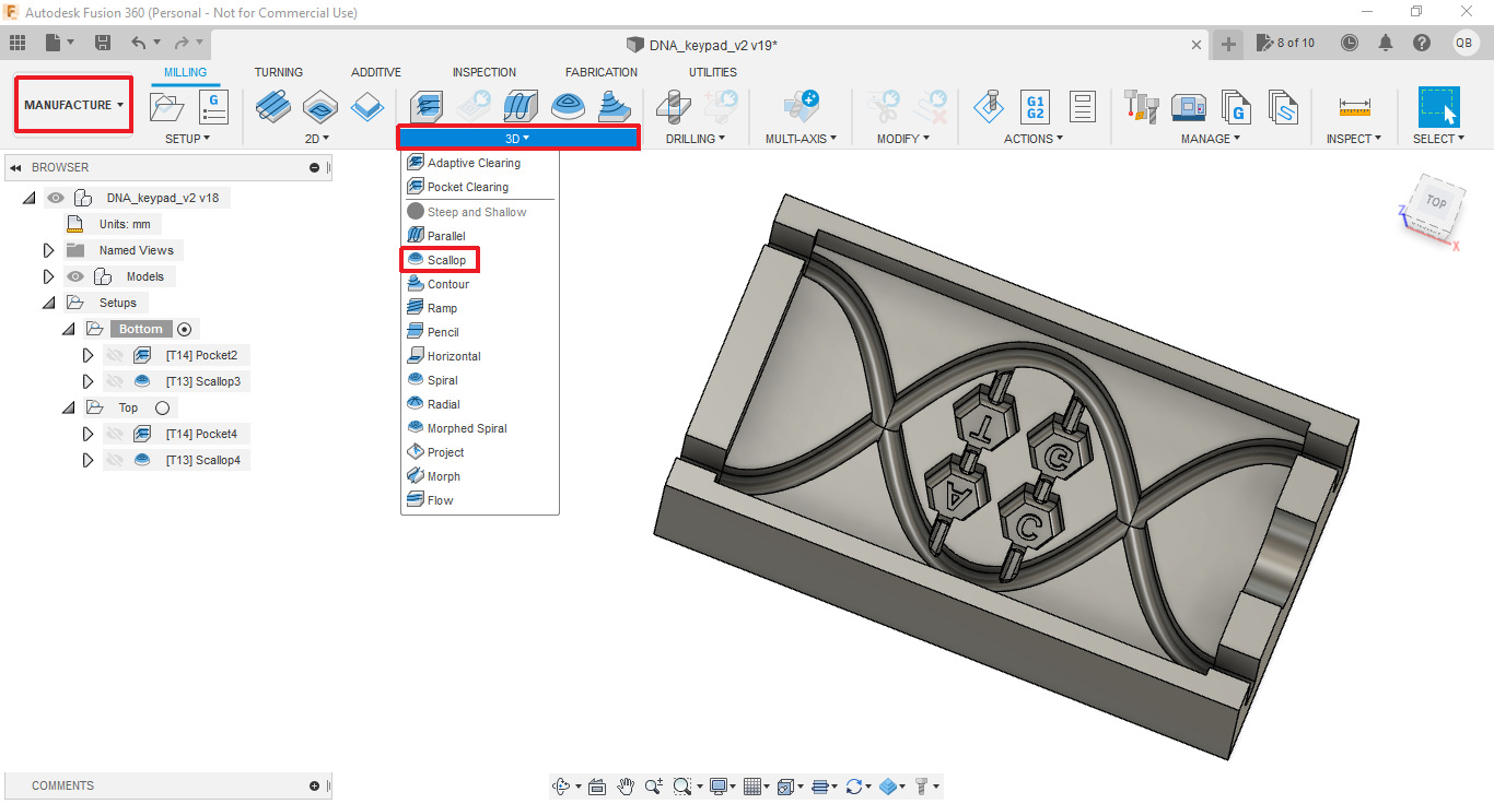
Create 3D finish cut operation - Fusion 360
9 - Configurate finish cut parameters (tool, clearance height, step over, ramp type, etc), and simulate operation as for the rough cut operation.
10 - Export each cut operation to the appropriate format for your CNC machine (right click on the cut operation -> “PostProcess”) :

Export cut operation - Fusion 360
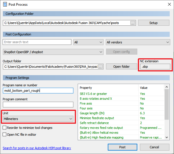
Export cut operation parameters - Fusion 360
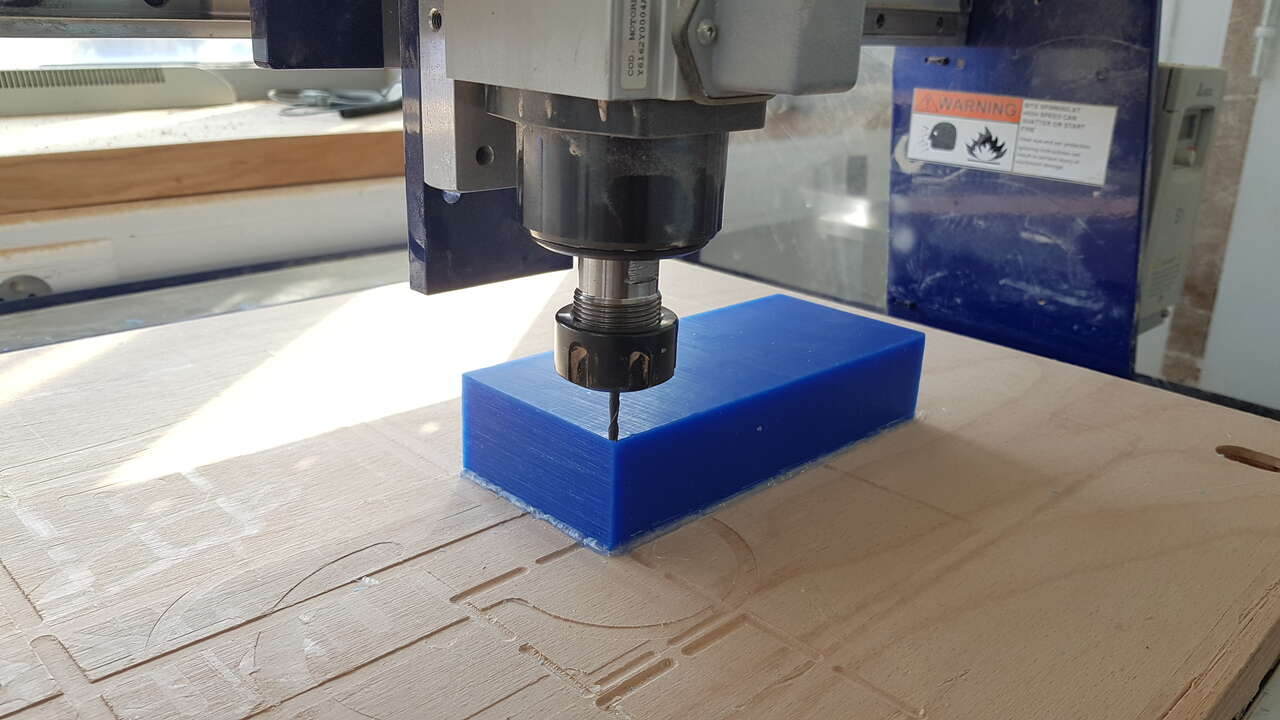
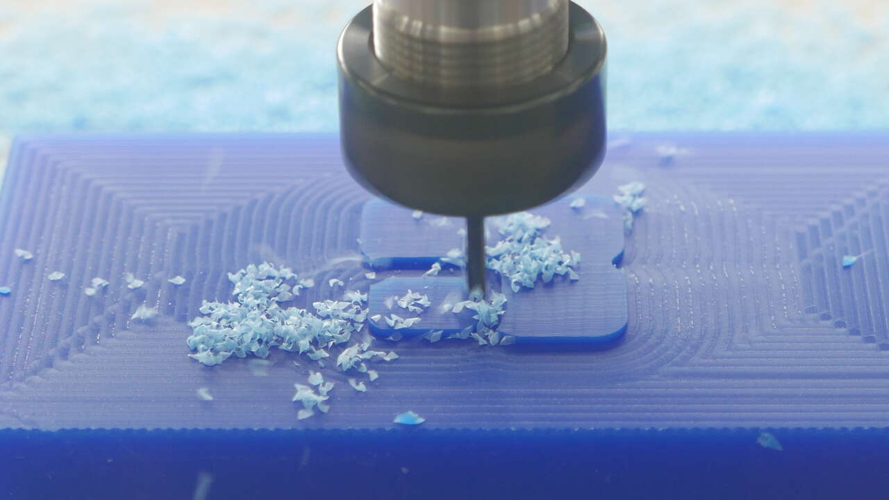
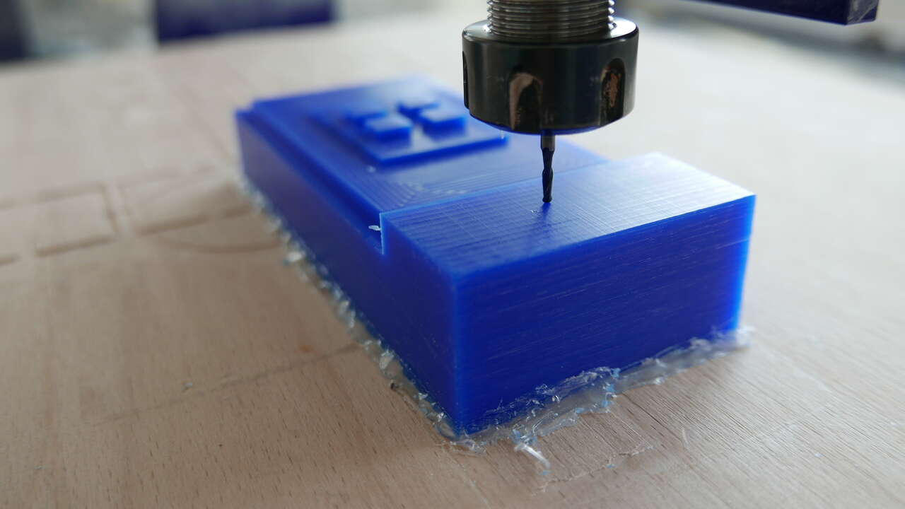
CNC milling
The CNC machine available at fablab Digiscope is a ShopBot Desktop. Its work area is 24” x 18”.
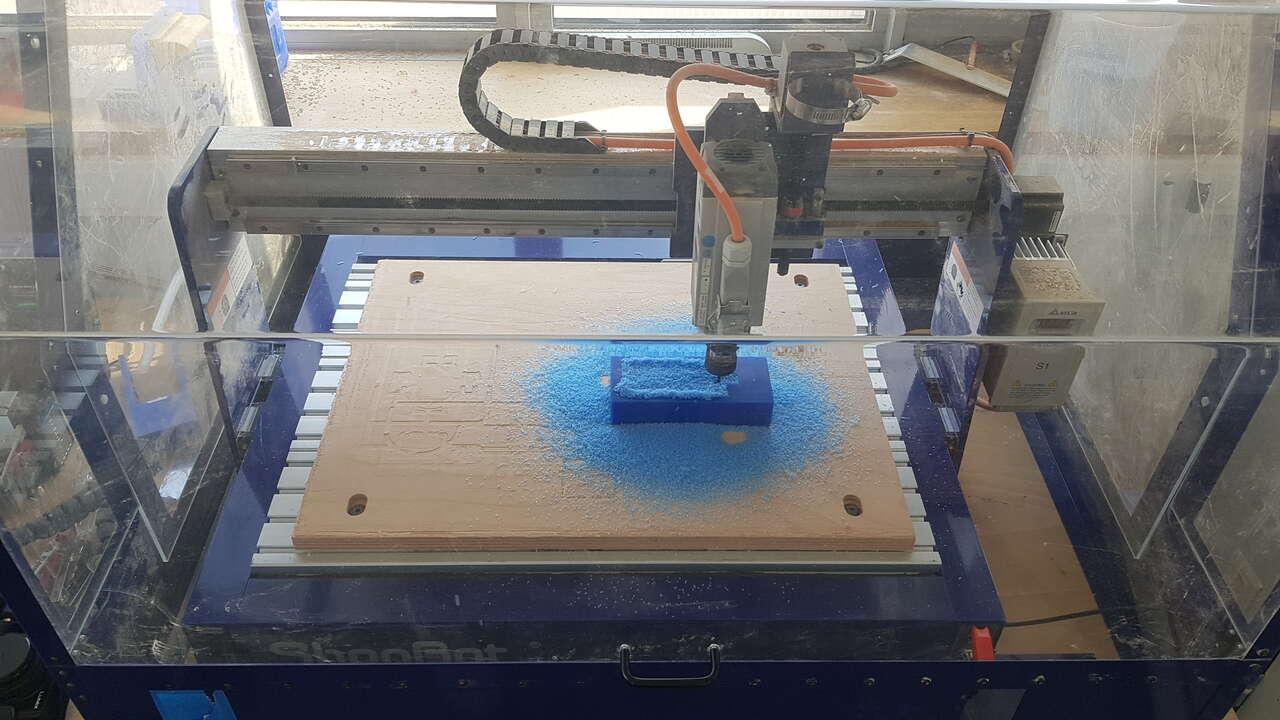
ShopBot Desktop
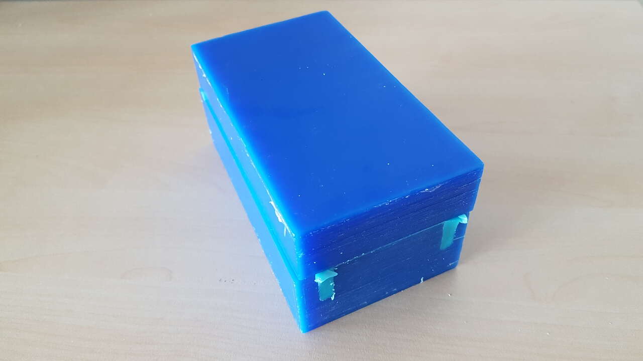
I have used Freeman 81-004-025 machinable wax blocks to mill the 2 parts of my mold.
- Measured dimensions : 175 x 75 x 37 mm
In this section I will not go into details about the use of the CNC machine as it has already been covered widely in week 07, but rather present a few pictures of the cut operations.
Two different end mills have been used :
- rough cut : Tool 13 in the screenshot below. Flat end mill.
- finish cut : Tool 14 in the screenshot below. Ball end mill.
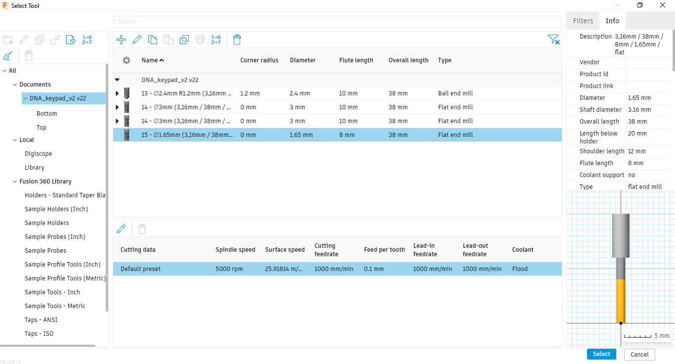
End mills details - created in Fusion 360 library
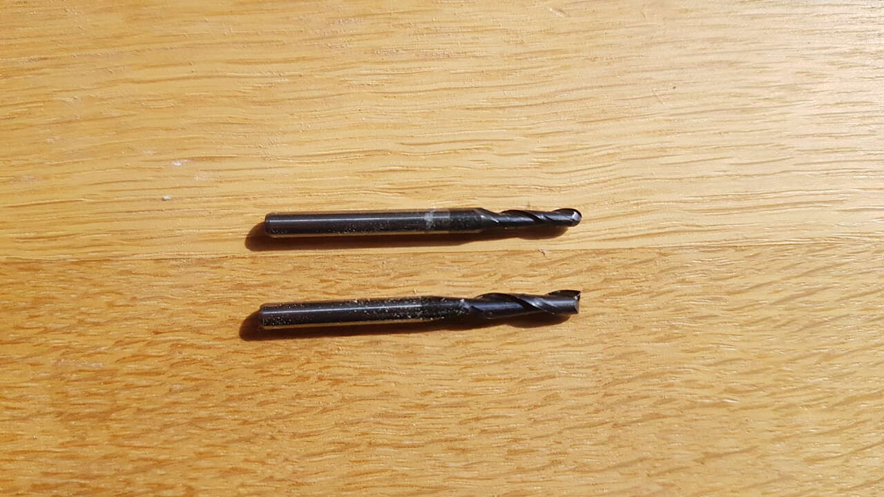
End mills : ball end mill (top), flat end mill (bottom)
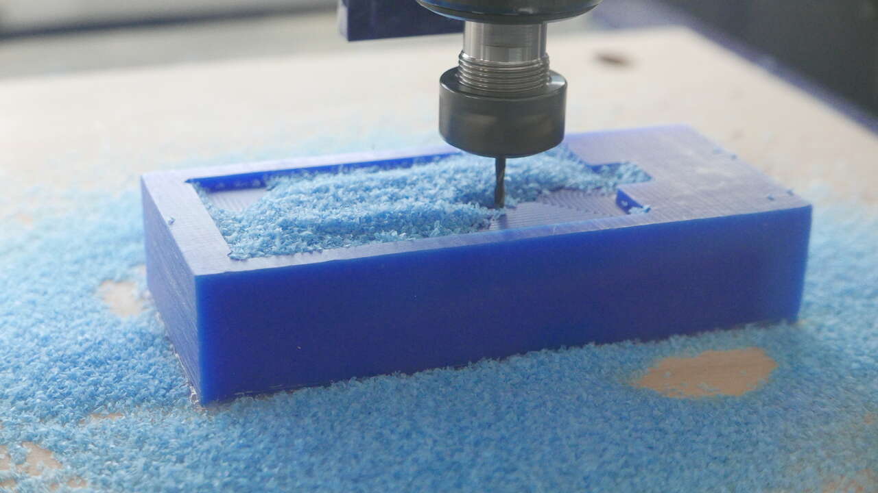
Milling the bottom part of the mold :
 |
 |
| CNC zeroing - x/y axis | CNC milling bottom mold - rough cut ongoing |
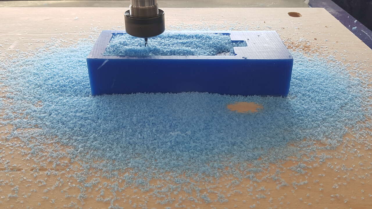 |
 |
| CNC milling bottom mold - rough cut ongoing | CNC milling bottom mold - rough cut completed |
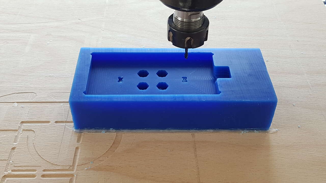
 |
 |
| CNC milling bottom mold - finish cut ongoing | CNC milling bottom mold - finish cut completed |
Warning: I observed a short offset on the y axis for the finish cut of the mold bottom part (which explains why the cut is not perfectly centered in the end on that particular axis). I am convinced that this offset occured when I changed the milling tool between the rough cut and the finish cut. After the tool change I just permormed the zero calibration on the z axis, and I did not make sure that the calibration was still correct on the x and y axis.
Based on those observations, I made sure that all axis were calibrated properly after the tool change for the mold top part, which in the end gave me a perfect result.
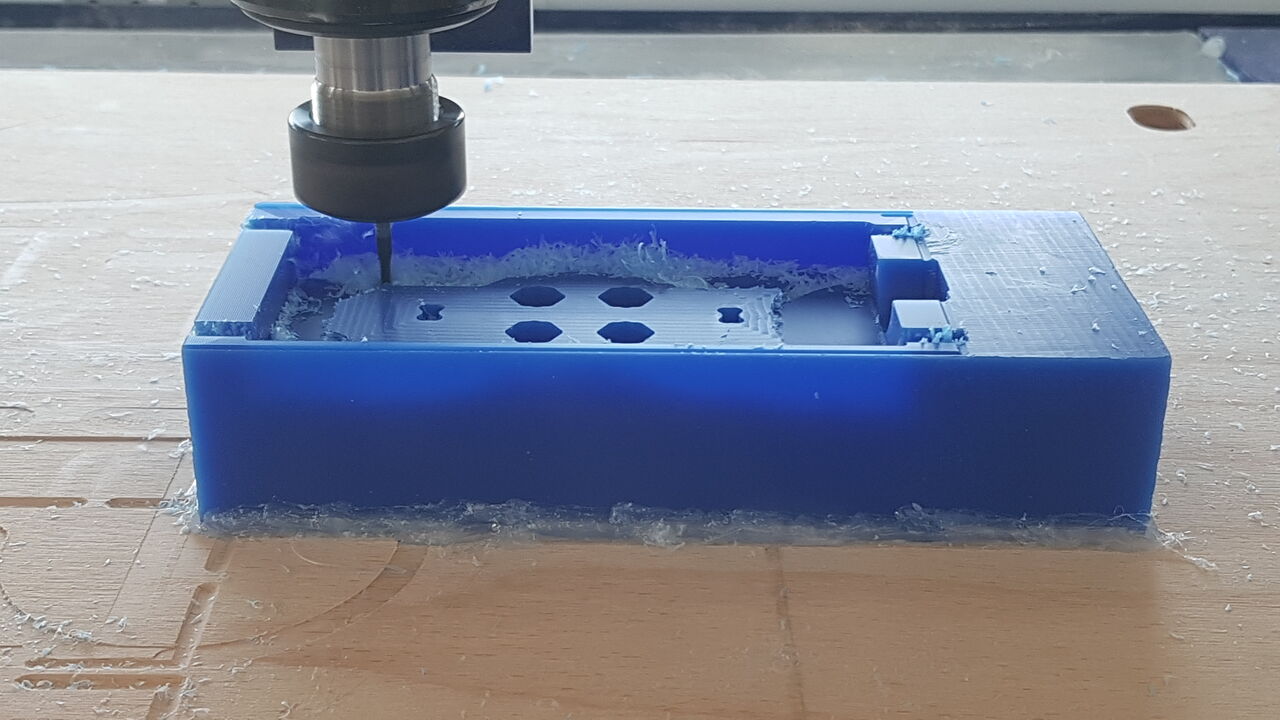
Milling the top part of the mold :
 |
 |
| CNC milling top mold - rough cut ongoing | CNC milling top mold - rough cut completed |
 |
 |
| Tool change between rough and finish cuts | Verifying x/y axis zero after tool change |
 |
 |
| Zeroing z axis after tool change | CNC milling top mold - finish cut completed |
Note : It can be useful to sometimes pause the cut operation for taking the chips away from the material to obtain a better cut and a better control over the cut operation. In order to do so, simply press the space bar (applicable for the Shopbot CNC machine). To resume operation, simply click on the “Resume” button of the popup that appeared :
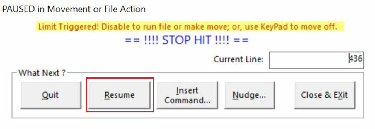
Resume cut
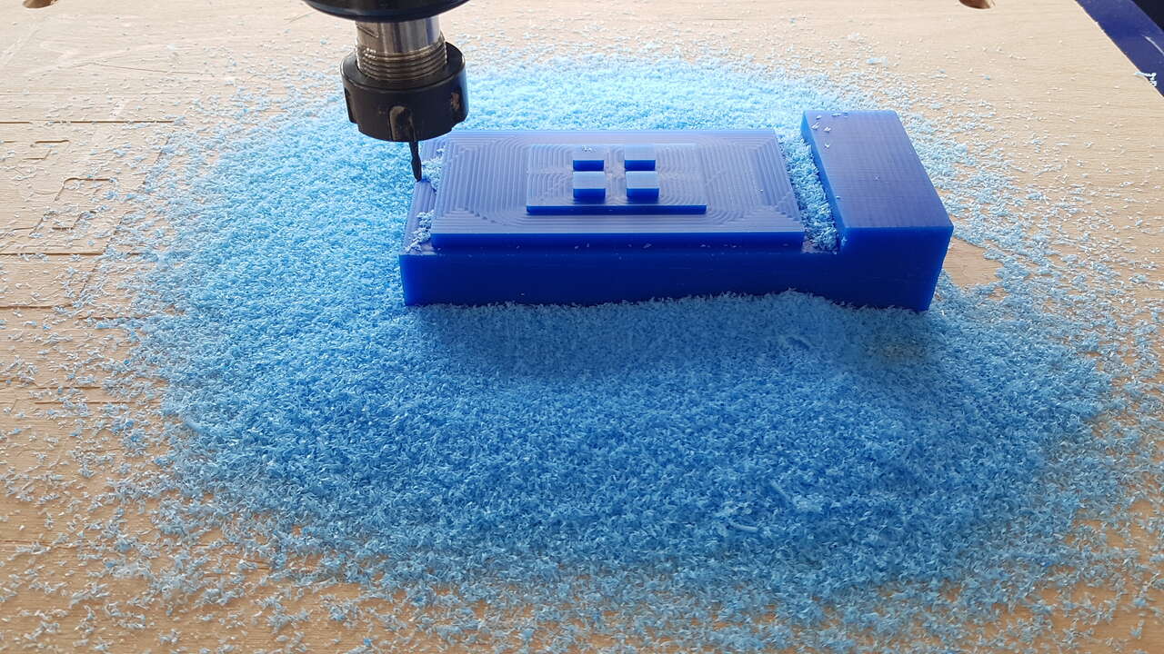
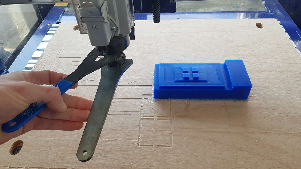
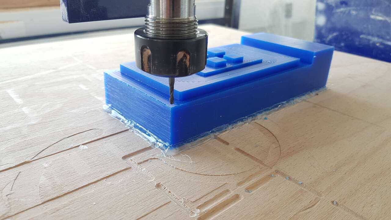
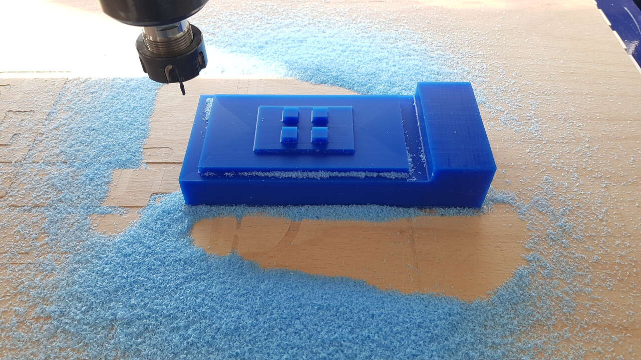
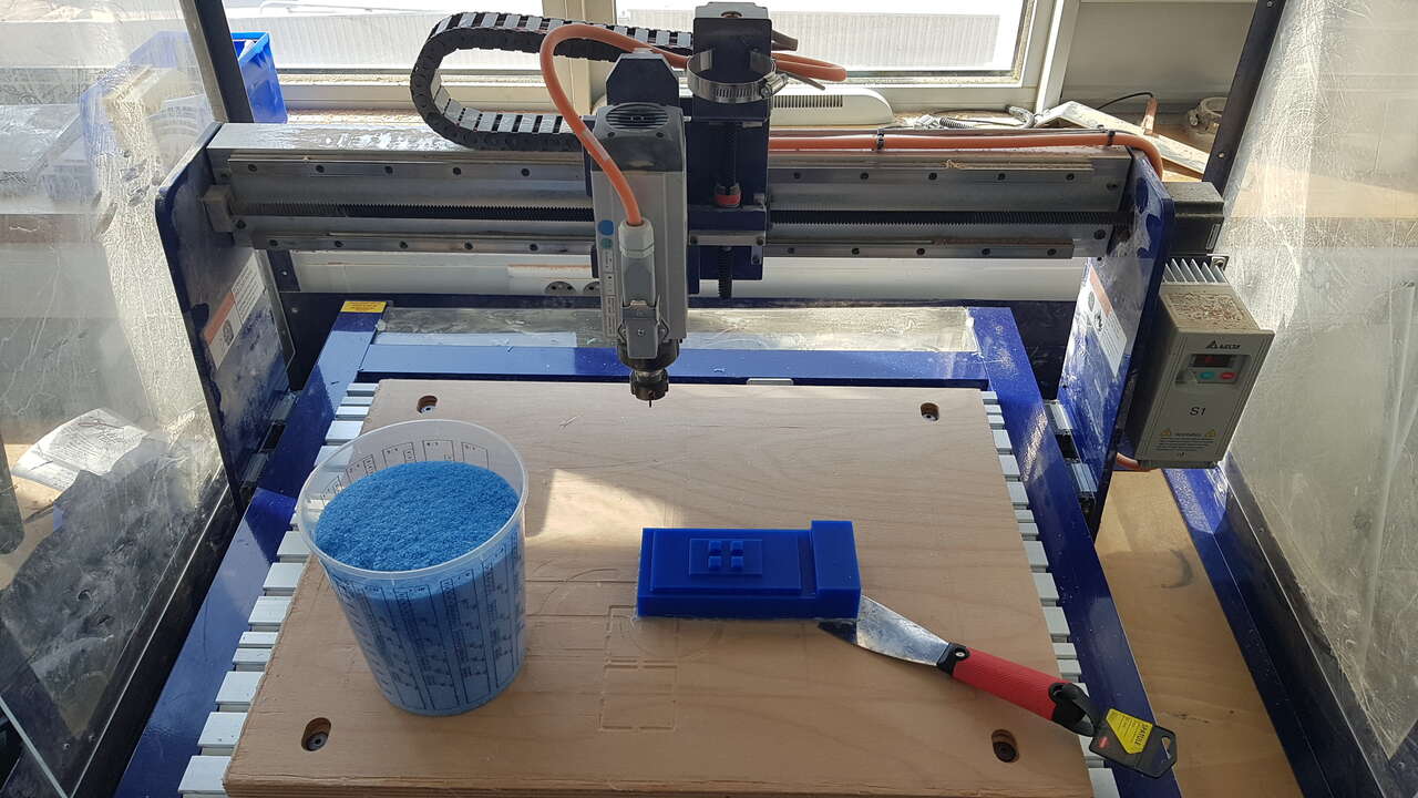
Once the cut operations completed, I removed the part from the machine’s bed using a cutter and a spatula, and also collected the wax chips as they can be melted and reused.
End mills : ball end mill (top), flat end mill (bottom)
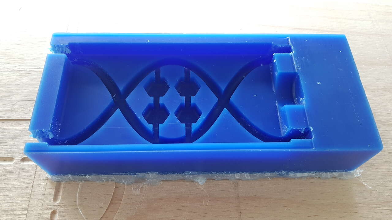
Results
Last step before being able to cast silicone into the mold was to cut the undesired parts of the was blocks. I could have had done it with the CNC but we do not have long enough end mills for it, and as the wax is a relatively soft material it was pretty simple to saw it. Also I filed little impurities inside in order to obtain a better material flow inside the mode.
Sawing undesired parts of the mold parts
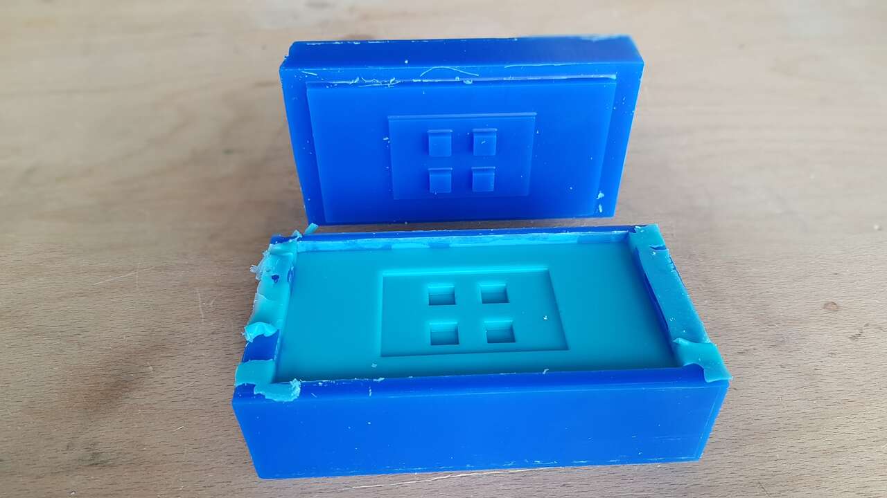
Mold parts - final result
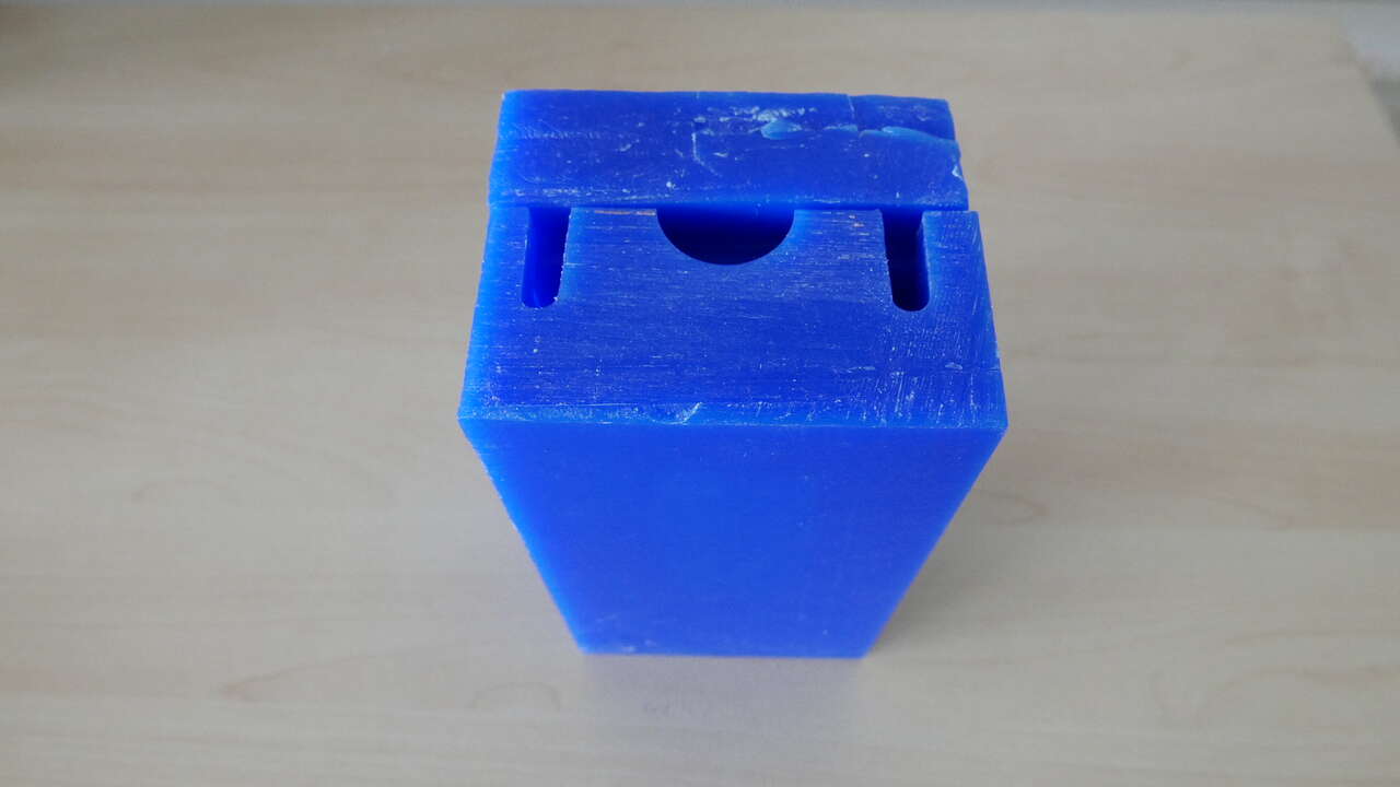
Mold assembly
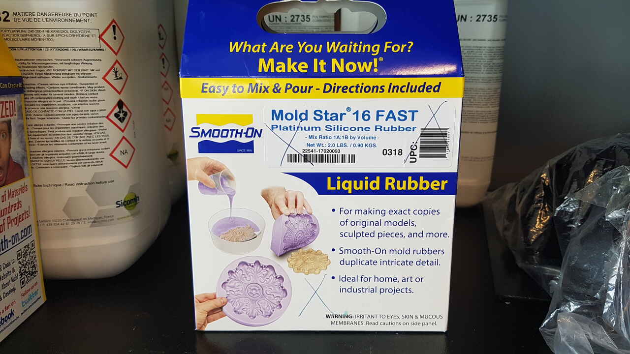
Silicone casting
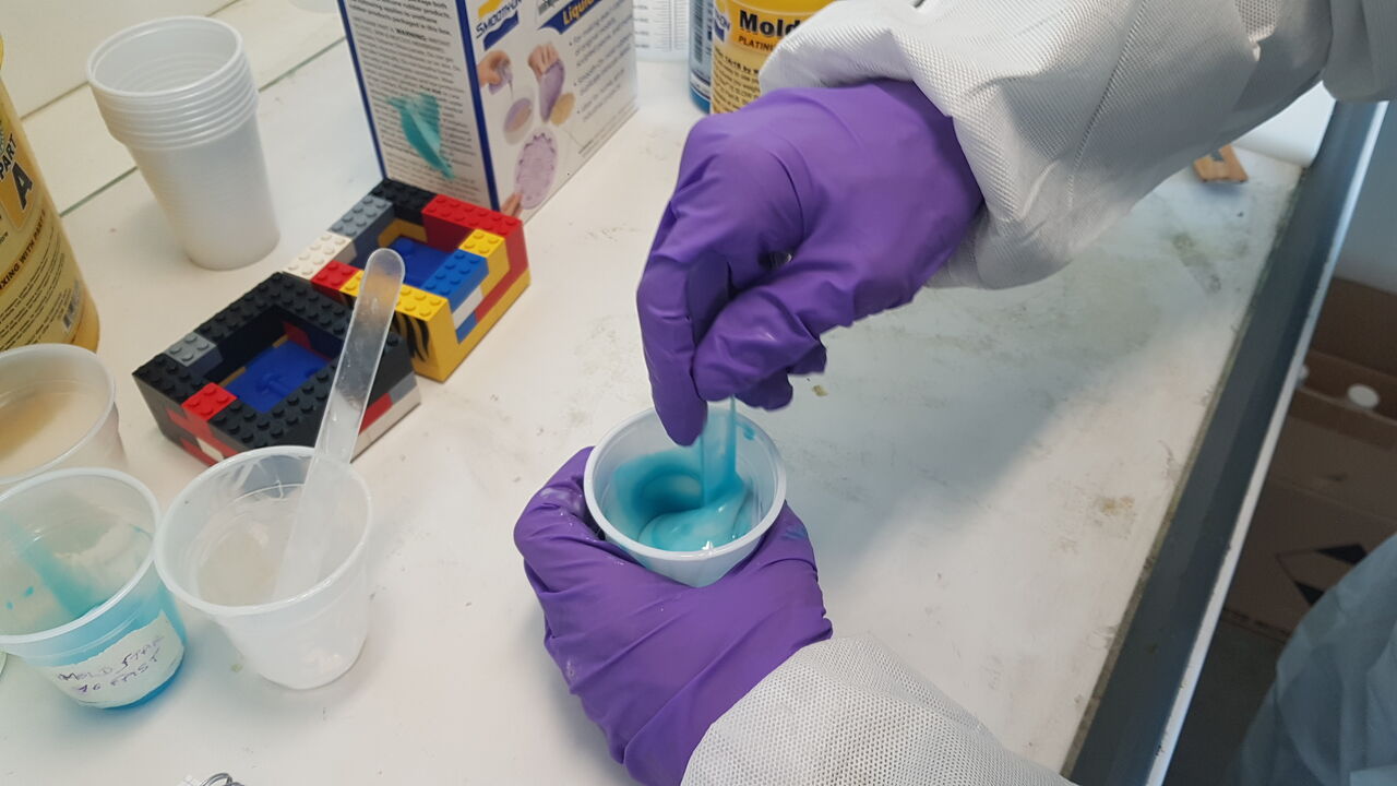
Based on the results obtained with our test casts, I decided to use the Smooth-On Mold Star 16 FAST. Even though the blue color was not really appropriated to my project , I chose this silicone as the shore hardness was exactly the one I was looking for.
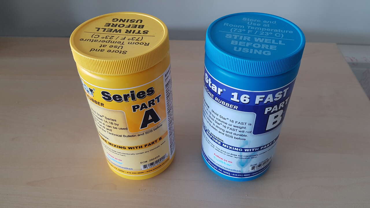 |
 |
| Smooth-On Mold Star 16 FAST - pots | Smooth-On Mold Star 16 FAST - packaging |
Before using this product, I read the instructions and the safety datasheet.
Most important parameters:
- Mix ratio : 1A/1B
- Pot life : 6 min
- Cure time : 30 min
- Density : 1.18g/cm3
- Shore hardness : 16A
Before preparing the silicone for casting, I calculated the quantity of material necessary. In order to do so, I combined my part’s volume given by Fusion 360 and the silicone density.
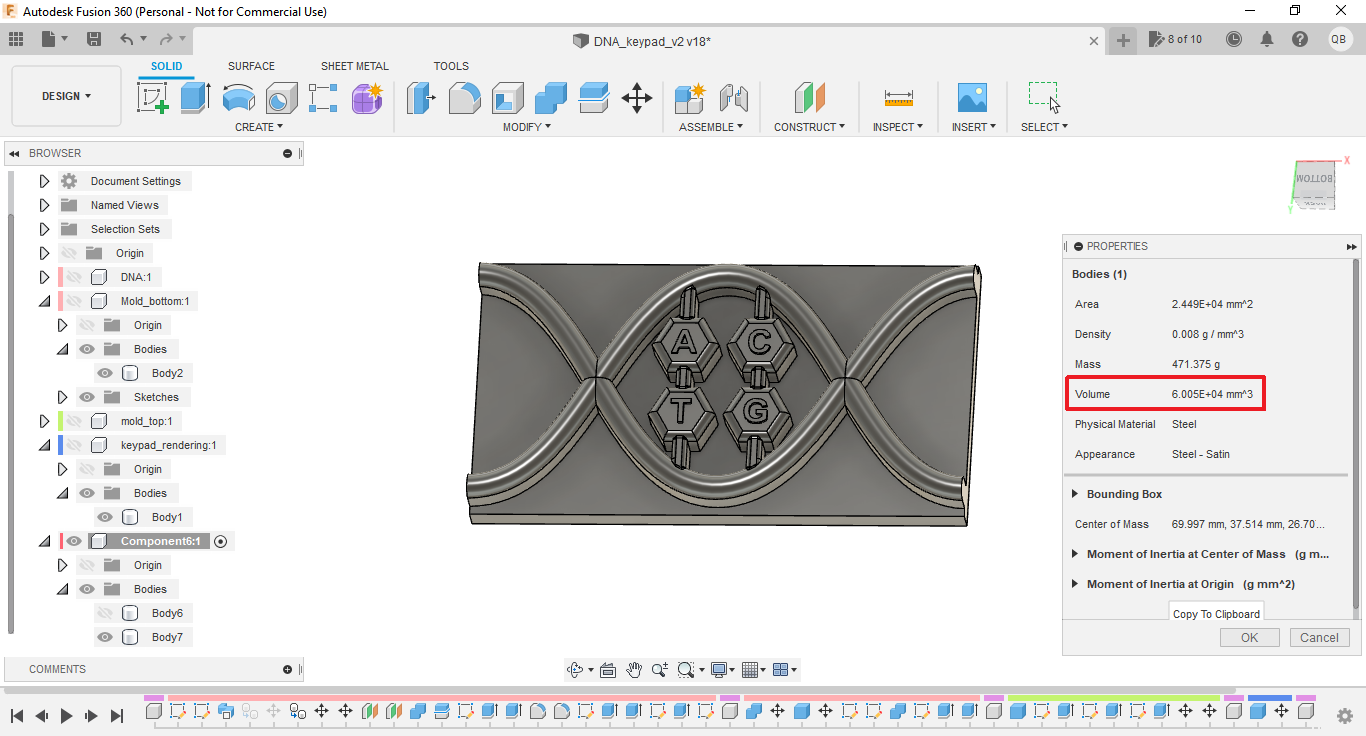
Keypad volume - Fusion 360
Mold Star 16 FAST, density = 1.18g/cm3. My part is announced as 60 050 mm3, which corresponds to 60.05 cm3.
60.05 x 1.18 = 70.85 g.
As the part volume calculation does include the filling holes, and that I also needed to take into account the material loss in the preparation process, I decided to prepare a total quantity of silicon of 96g (48g part A, 48g part B).
1 - Pour the desired quantity of Part A into a first container, and mix it for about 1:30 min.
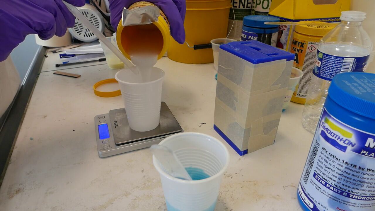
Preparing Part A
2 - Pour the desired quantity of Part B into a second container, and mix it for about 1:30 min.
Preparing Part B
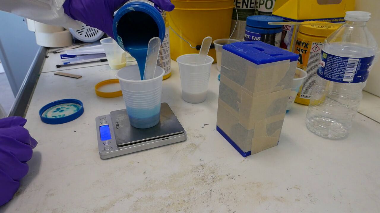
3 - Pour the content of one container into the other (in my case A into B).
Pouring Part A into Part B
4 - Mix thoroughly both parts for 2 minutes by taking care of not creating bubbles. The mixture obtain must be homogeneous.
Mixing Part A and Part B
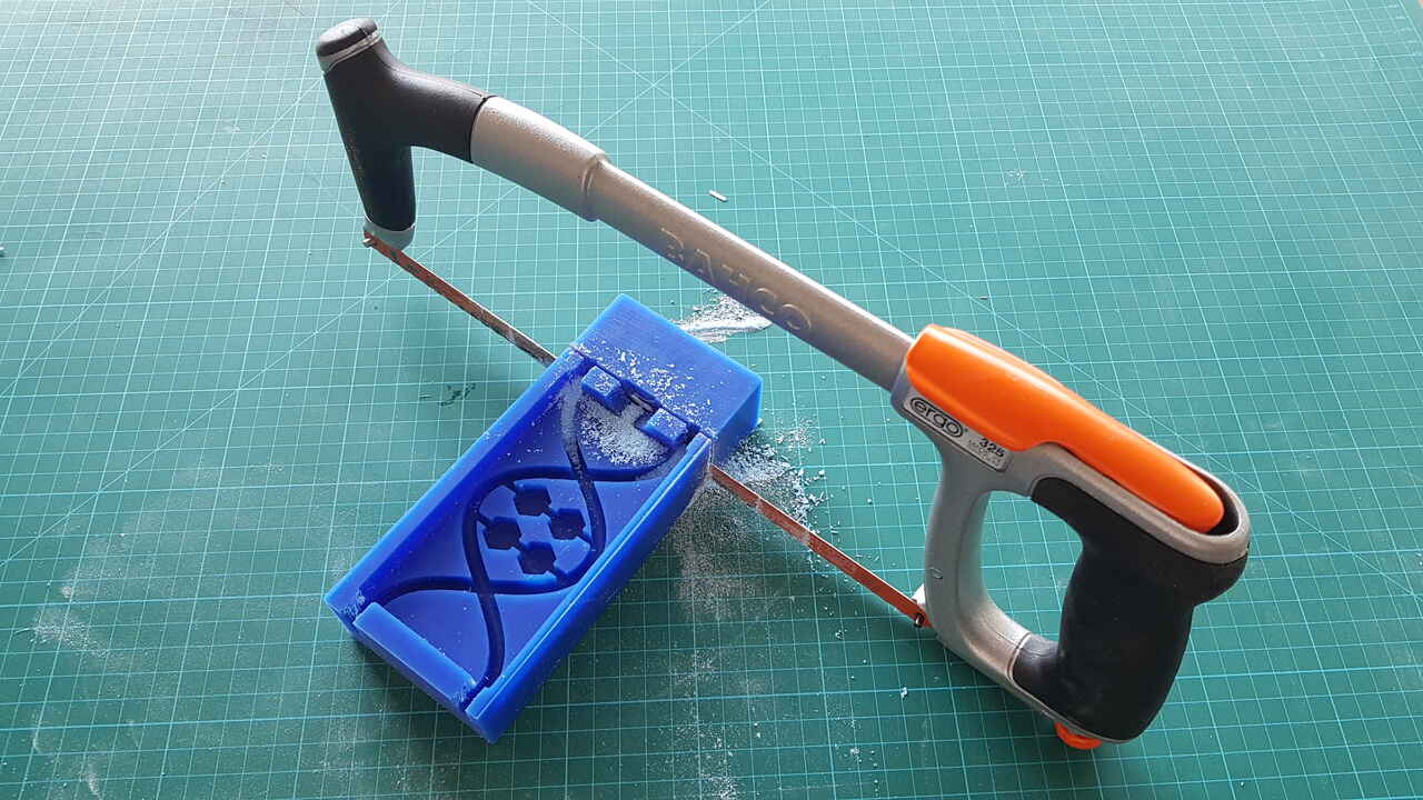
5 - Cast the silicon mix into the mold.
Warning: Given that the pote life is 6 min, this step must be performed quite rapidly.
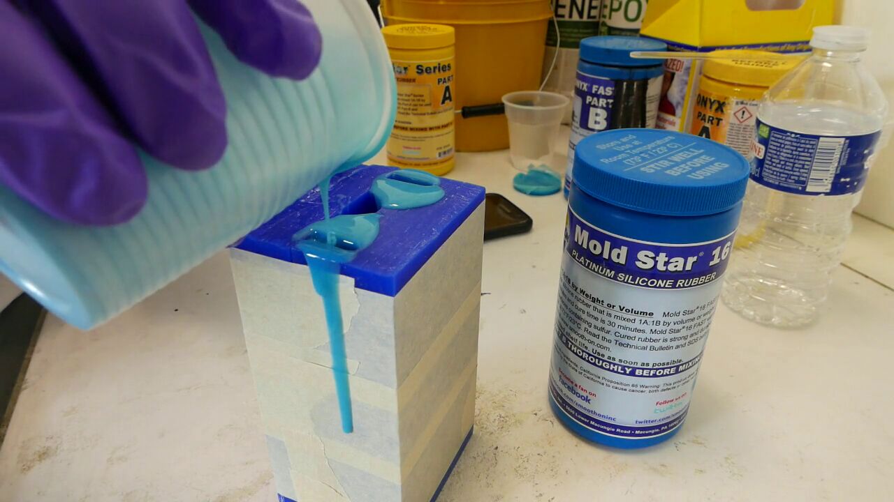
Casting silicone into the mold
6 - Wait for a time at least equal to the cure time (indicated as 30min).
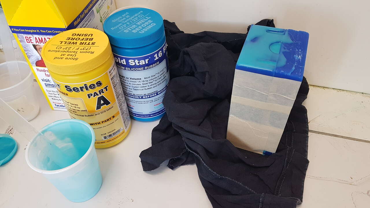
Mold filled with silicone
Although I was quite impatient to see the result, and that the cure time is given as 30min, as a precaution I decided to wait 1h15 before opening the mold.
Mold before opening
Mold opened
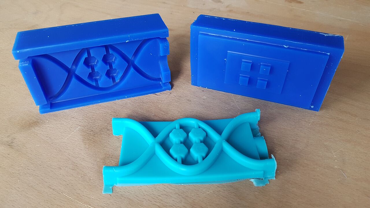
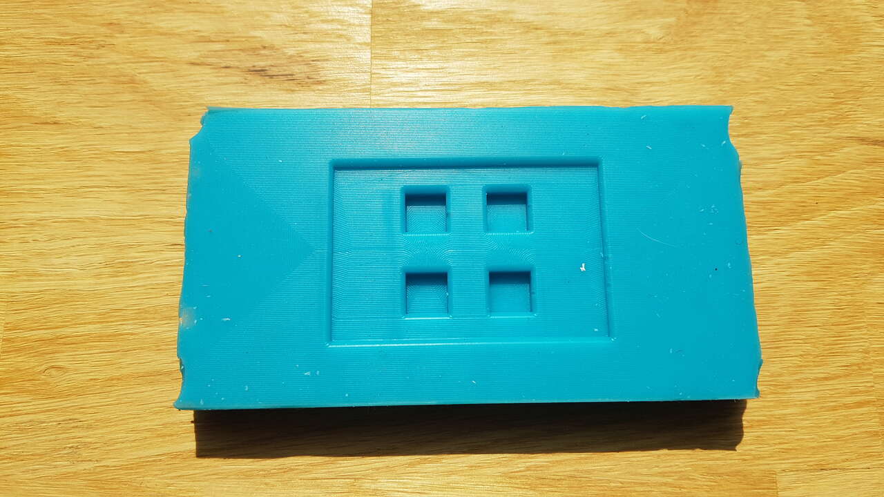
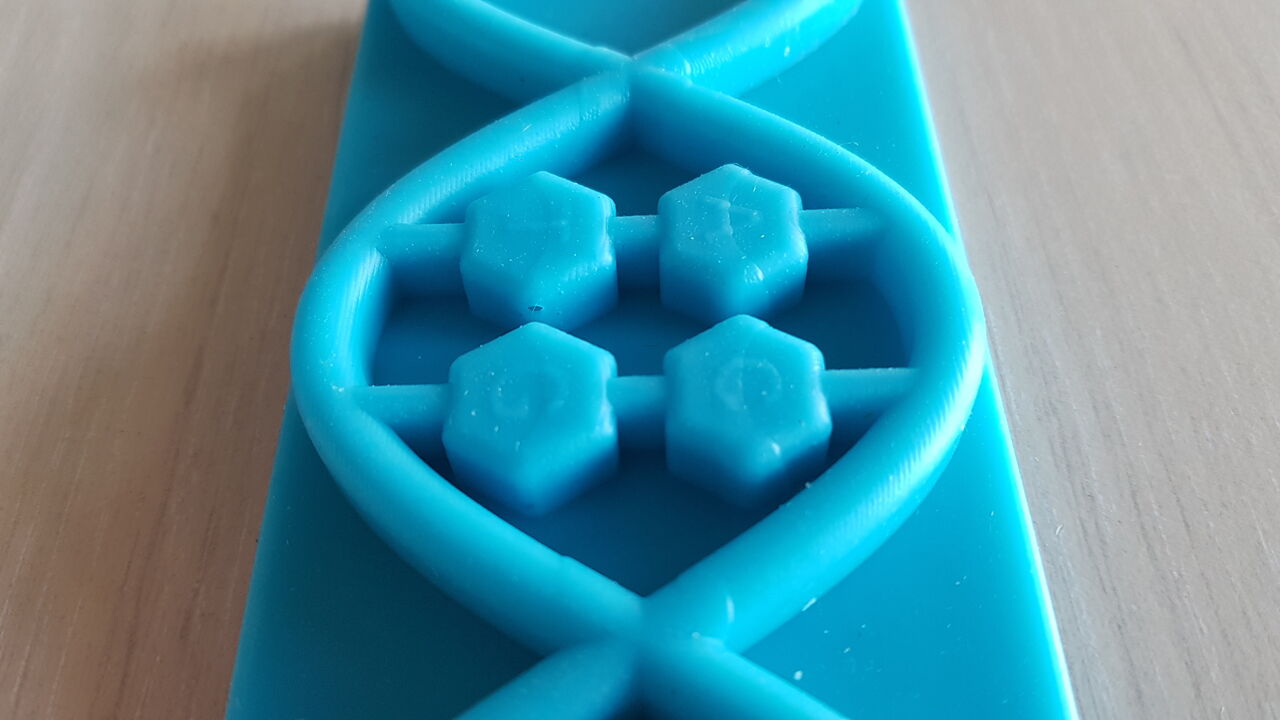
Keypad front side before cleaning
Once the keypad taken out of the box, I cut the undesired parts (filling holes and overflow) using a cutter, and here is the result I obtained :
Keypad front side
Keypad back side
The idea was then to prepare a PCB with 4 push buttons that fits into the dedicated holes, but unfortunately the laser cutter was quite busy this week in our fablab so I did not have the chance to make it on time for this week. Nevertheless herebelow is presented how the push buttons will fit into the keypad.
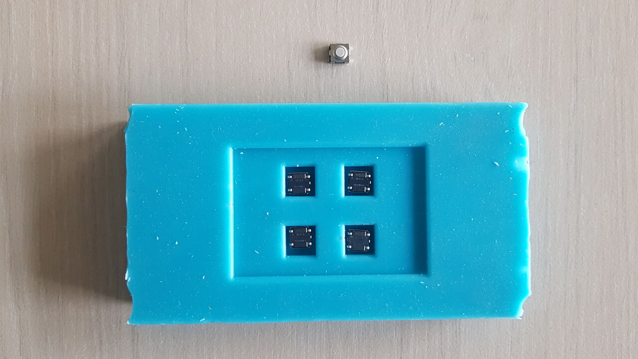
Keypad with push buttons at the back - demonstration
Even though it was not completed yet, I could confirm that pressing on the silicone buttons activated the push buttons because I could hear the clicks.
A few days later, I managed to allocate some time to successfully finish this activity with the PCB production / soldering, keypad integration test in cardboard, and Arduino testing !
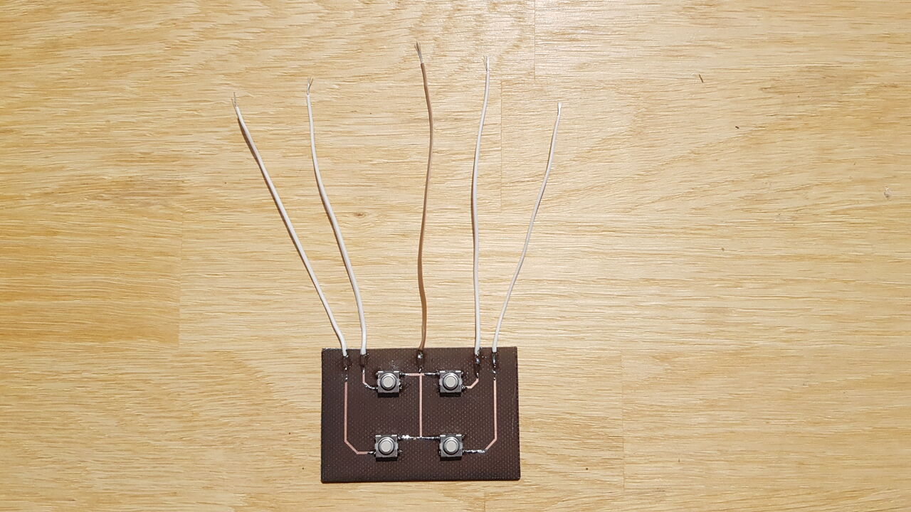
PCB with buttons to be integrated in the DNA keypad
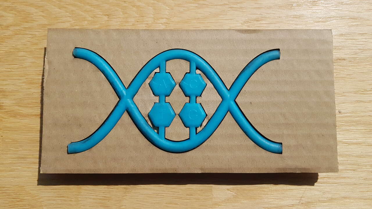
Keypad integration test in laser cut cardboard
Main issues
A few bubbles can be seen on the keypad, as the one presented in the image below, but it is very minor and will not impact at all the keypad functionality.
Keypad little air bubble
Source files
The source files of the work presented in this week assignment are available for download here :
- DNA keypad : STEP files / Fusion 360 model available on YouMagine plateform.
- Buttons PCB : Eagle design