14. Interface and application programming
Assignments:
Individual assignment:
- Write an application that interfaces a user with an input &/or output device that you made.
Group assignment:
- Compare as many tool options as possible.
HC-06 Bluetooth module
For my puzzle box final project I want to develop a user interface to allow control over different elements such as the countdown, the lock mechanisms, the RGB LED, etc. After few searches on the internet, I rapidly decided to order a HC-06 Bluetooth module for its implementation simplicity, for the important quantity of tutorials available on the internet and also because it requires only 2 pins of the microcontroller (Rx and Tx for serial communication).
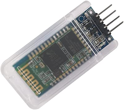
HC-06 Bluetooth module
For information, there also exists a HC-05 Bluetooth module variant, which offers the possibility to work either as a controller or as a peripheral. It means that this device, unlike the HC-06 module, is able to initiate Bluetooth connection to another device. As I do not need this functionality for my project I decided to stick to the HC-06 module.
Arduino Bluetooth Controller
HC-06 - Arduino testing
The first thing I did before trying to control something through the Bluetooth module was to make sure that I could establish serial communication between the HC-06 module and my Arduino Uno. In order to do so I have followed the Aranacorp tutorial (in french) that gave me the setup schematic with the voltage divider bridge (to transmit 3.3V signals to the HC-06 module) and also examples of Arduino codes.
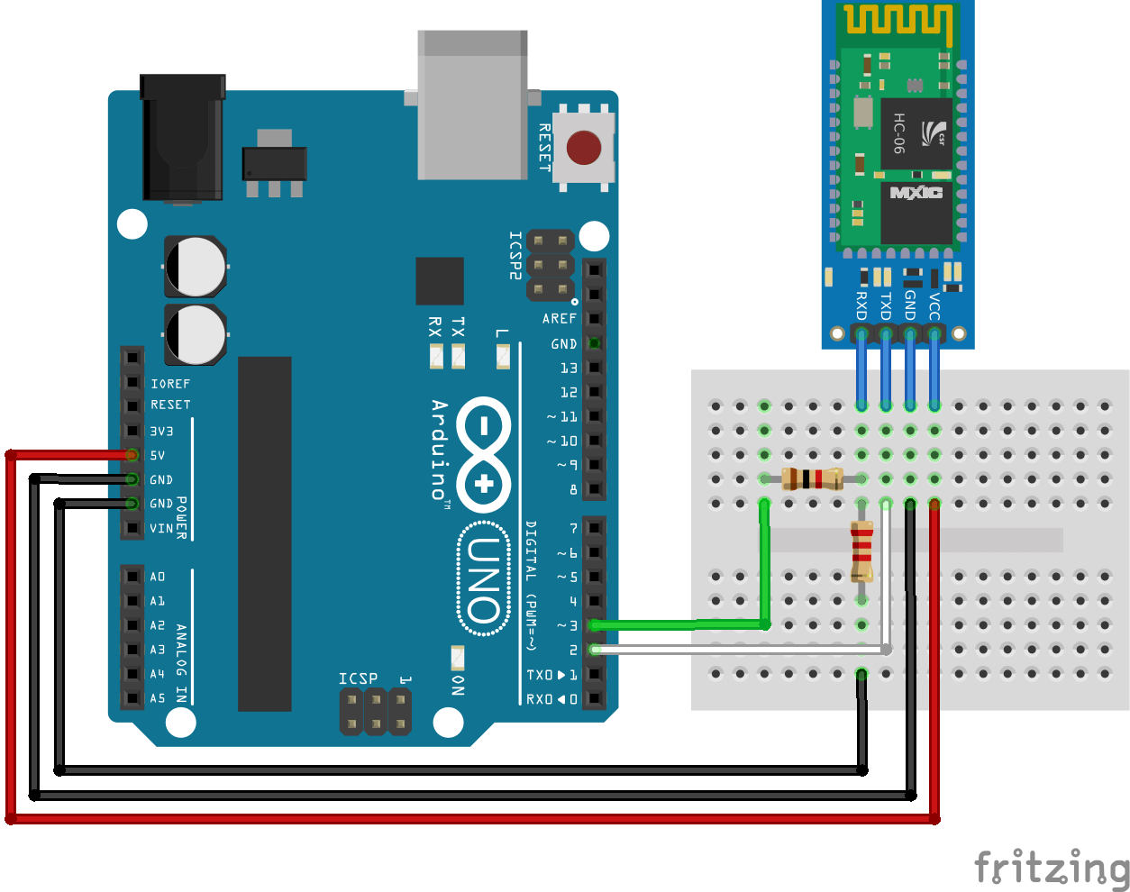
Bluetooth HC-06 module Arduino setup - Fritzing
Among the Arduino codes shared in the turorial mentiond above, the one in the “Bonus: scan du baudrate” section allowed me to check the HC-06 module baudrate when received from the factory. The screenshot below reveals that it was configured at a Baudrate of 9600. Indeed when the HC-06 module receives the “AT” command on the serial line it responds “OK” when baudrate is correctly configured.
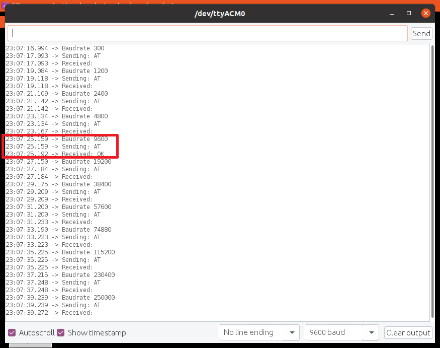
Bluetooth HC-06 module - Baudrate check
Notes : This first test required to use the Software Serial communication between the HC-06 module and the Arduino to let the Serial line available for communication between the Arduino and the computer.
For the following tests, I did not need serial communication between my computer and the Arduino, so I directly connected the Rx/Tx pins of the HC-06 module to the Tx/Rx pins of the Arduino (still using the voltage divider bridge). Getting inspiration from Aranacorp tutorial and Pecquery tutorial for programming, and from Alex M.Smith tutorial for using the Arduino Bluetooth Controller application, I came up with an Arduino program that allowed me to control the embedded LED of the Arduino Uno via the terminal mode of the Arduino Bluetooth Controller application
- Sending ‘a’ from the application to the Arduino over Bluetooth, turns ON the LED.
- Sending ‘b’ from the application to the Arduino over Bluetooth, turns OFF the LED.
- A feedback has been implemented so that a message is displayed on the Arduino Bluetooth Controller application each time a character is received by the Arduino.
The Arduino Bluetooth Controller application offers 4 modes :
- Controller mode.
- Switch mode.
- Dimmer mode.
- Terminal mode.
I have personnally only experimented with the Terminal mode that allows to send any character through the phone keypad and the Controller mode that allows to map a dedicated character to 10 possible predefined buttons arranged as a gamepad (directional arrows, start / select buttons, etc).
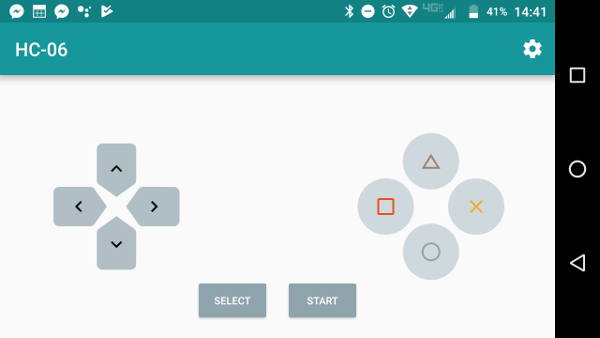
Arduino BT Controller - Controller mode
Puzzle box interface testing
Once those firsts tests successfully performed I could go on and create a phone application to interact with the puzzle box main PCB I designed and produced during the Networking and Communication week.
Note : When designing this PCB, I already did the necessary work to easily connect the HC-06 module. This implied letting the Rx/Tx pins of the Atmega328P available for this application and to add the voltage divider bridge.
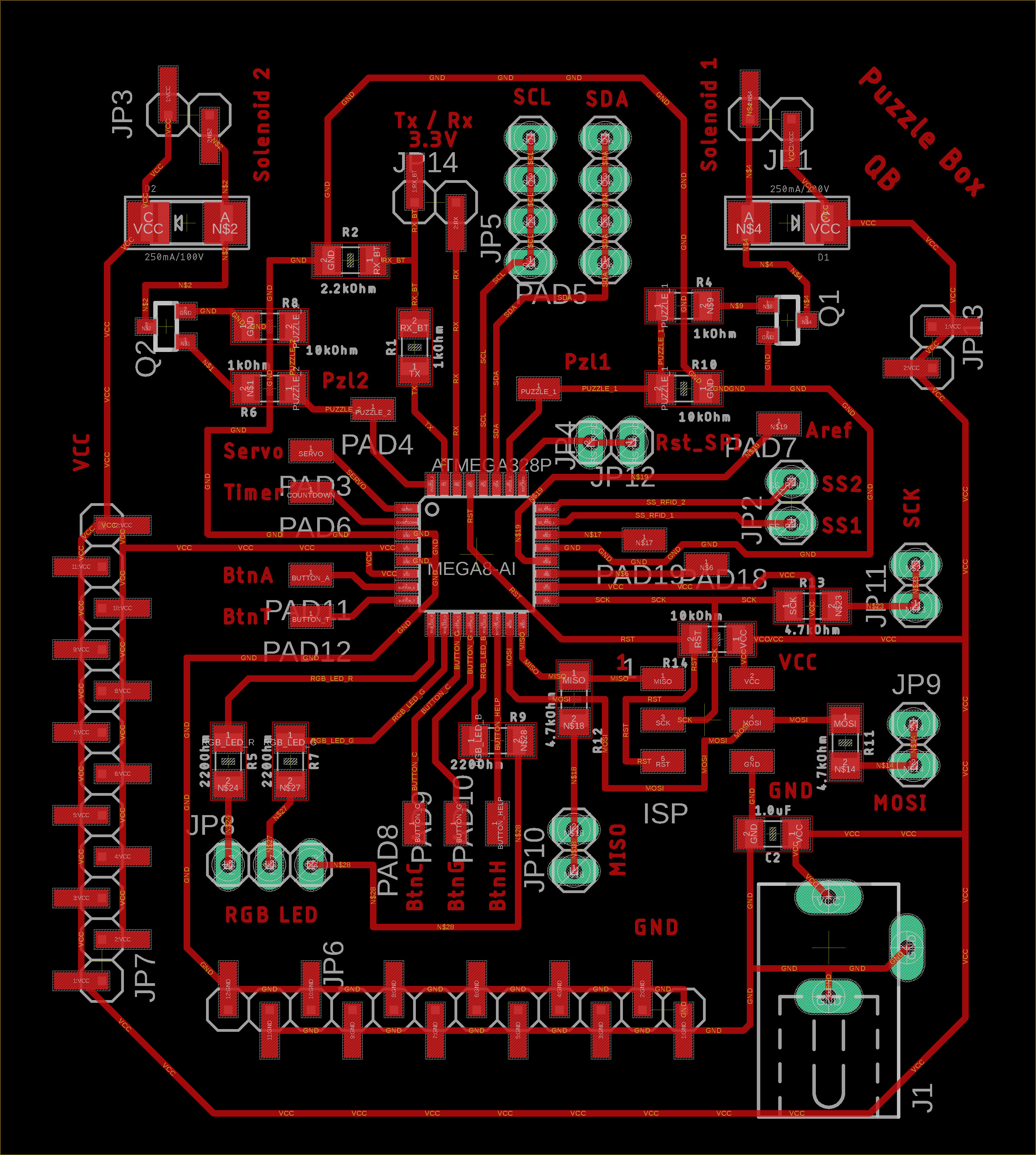 |
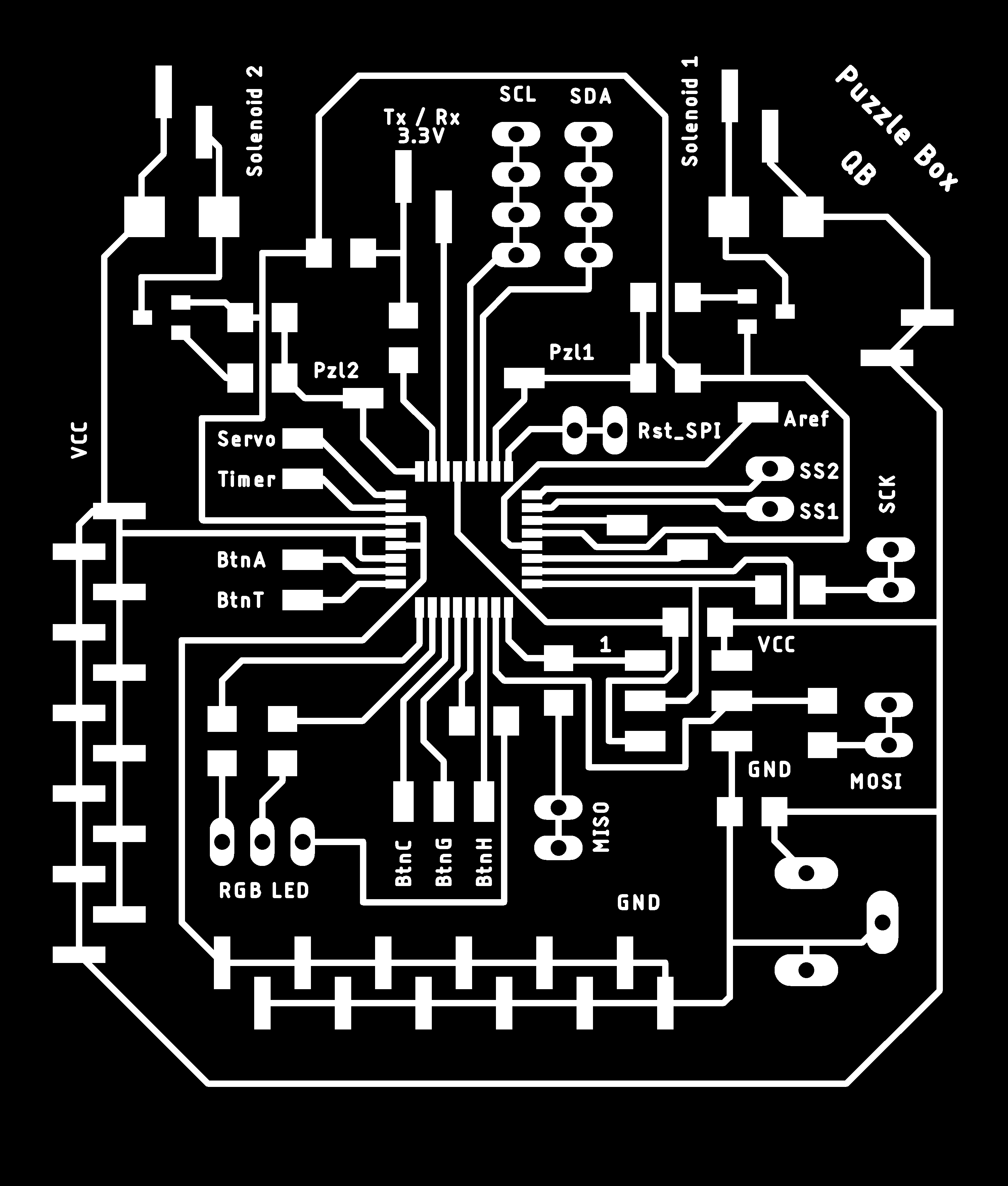 |
| Puzzle box main PCB - Eagle | Puzzle box main PCB (traces export) - Eagle |
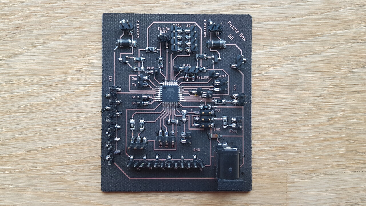
Puzzle box main PCB - completed
After few modifications in my main program to deal with the bluetooth communication, I rapidly came up with successful interaction between the Arduino Bluetooth Controller application and my puzzle box electronics as demonstrated in the video hereunder :
Note: I apolagize for the LCD text that can unfortunately not be read due to light conditions issues.
A few examples of the controls implemented :
- Sending ‘r’ from the application to the microcontroller over Bluetooth, turns on the RGB LED in red.
- Sending ‘g’ from the application to the microcontroller over Bluetooth, turns on the RGB LED in green.
- Sending ‘b’ from the application to the microcontroller over Bluetooth, turns on the RGB LED in blue.
- Sending ‘o’ from the application to the microcontroller over Bluetooth, turns off the RGB LED.
- Sending ‘s’ from the application to the microcontroller over Bluetooth, starts/resumes the countdown.
- Sending ‘p’ from the application to the microcontroller over Bluetooth, pauses the countdown.
- A feedback has been implemented so that a message is displayed on the Arduino Bluetooth Controller application each time a character is received by the microcontroller.
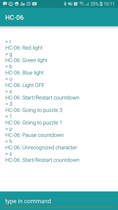
Arduino Bluetooth Controller - Terminal mode
Tha Arduino Bluetooth Controller application allowed me to easily test the bluetooth communication with my system, nevertheless due to the relatively limited possibilities offered by this application to create a custom interface I decided to move on to the MIT app Inventor.
MIT app inventor
The MIT App Inventor is an intuitive, visual programming environment that allows to rapidly build applications for smartphones and tablets, using a blocks-based approach.
Here below is presented a screenshot of the first version of the application I created and a video demonstrating how the application allows user to interact with the puzzle box electronics.
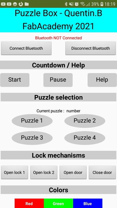
Puzzle box application - MIT App Inventor
Note : In the video, one can notice that the text of “Puzzle 1” and “Puzzle 2” buttons disappears when interaction occurs with the application. I did not understand this issue given that the 4 puzzle buttons were configured exactly in the same way. Nevertheless I later managed to fix this issue by rearranging all the puzzles buttons on the same line.
In order to use this tool, I read carefully the getting started tutorial, which especially allowed me to rapidly setup my Android phone and computer to start creating and testing in real time my application. Also I have been through some of the example tutorials, starting with a very basic one (Hello Purr tutorial). Then for configuring the buttons of my application to handle the Bluetooth connection to the HC-06 module, everything was explained in this Techno College Autant tutorial (in french).
1 - First thing to do was to create the design of my application, in the Designer view. This step was pretty simple, and consisted in dragging/dropping elements of diffrent types (buttons, labels, checkboxes, etc) from the “Palette” window to the “Viewer” window, and then adjusting the object properties to deal with font, size, alignment, etc.
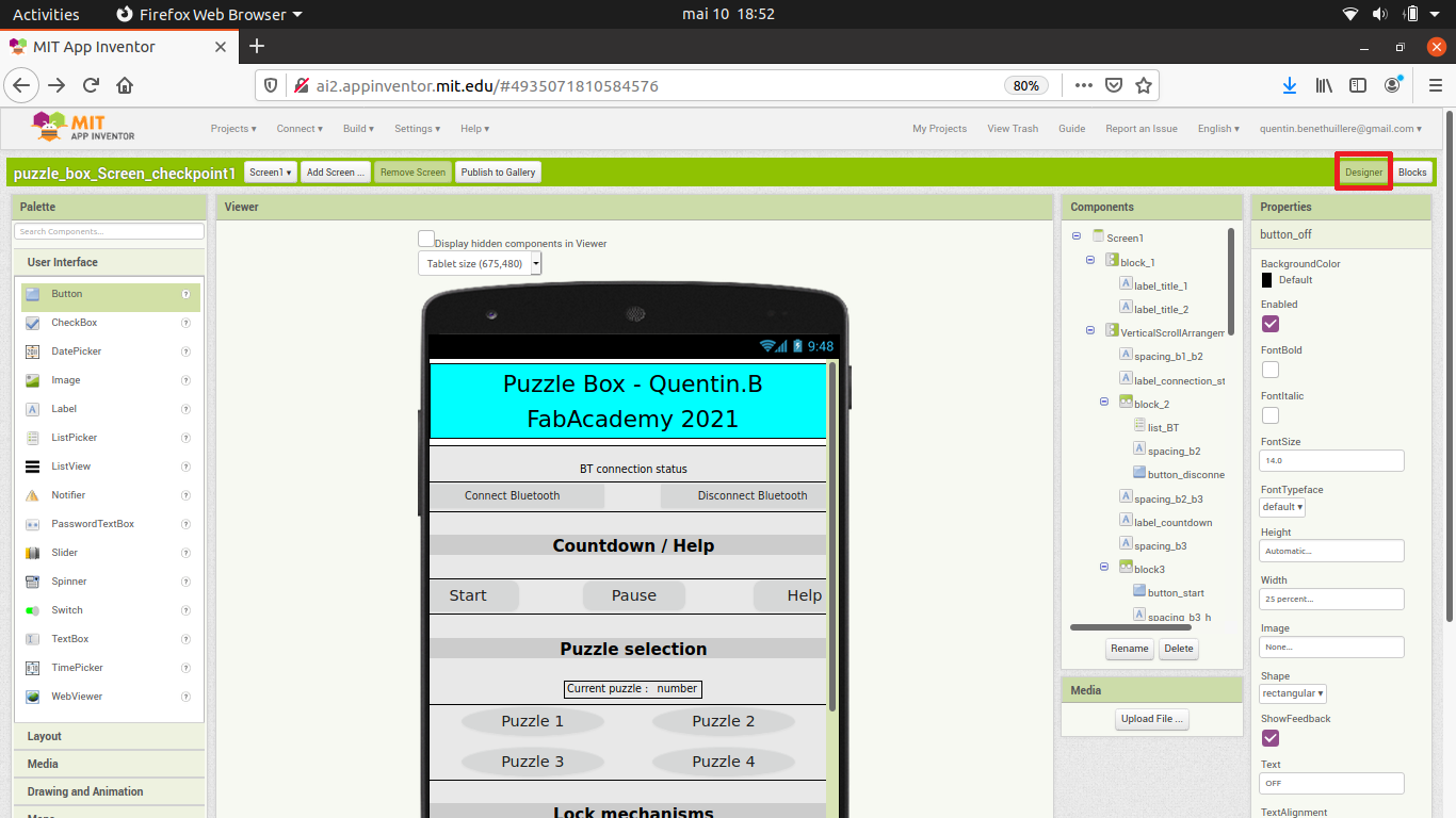
MIT App Inventor - Designer view
2 - Then functionalities must be allocated to the elements that makes up the application, and this was taken care of in the Blocks view. Once again, this step consisted in dragging/dropping blocks that could be assembled as pieces of a jigsaw puzzle.
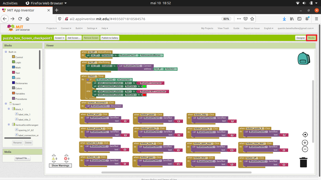
MIT App Inventor - Blocks view
In the screenshot above, the upper blocks deal with the Bluetooth functionality, and the others blocks deal with the buttons that allow to interact with my puzzle box electronics.
Note : As can be seen in the screenshot below, there exist several ways to allocate a character to a button :
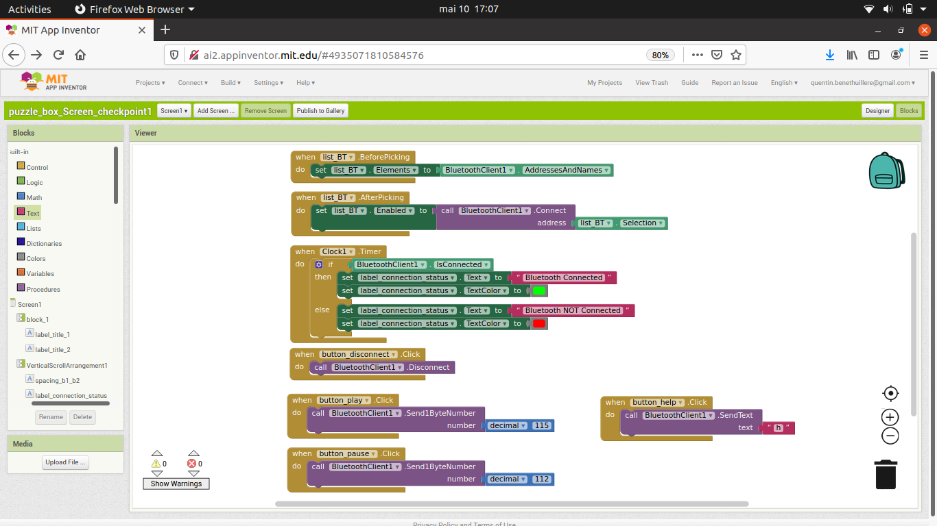
MIT App Inventor - Blocks view
3 - For testing the application in real time as I was developing it, I could establish a link between my computer and the MIT AI2 Companion application on my phone using either a QR-code or a 6 digits password. Note : This required both my computer and phone to be connected to the same wifi network.
MIT App Inventor - Communication with “MIT AI2 Companion” phone application
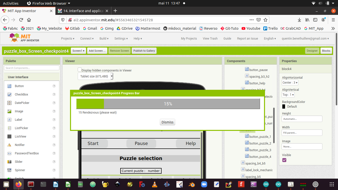
4 - Once I was happy with the application I developed and tested, I could generate the final application through the “Build” menu. Two options were available, either generating the application as an “.apk” file and then installing in the phone, or generating a QR code that would deal with the application installation on the phone.
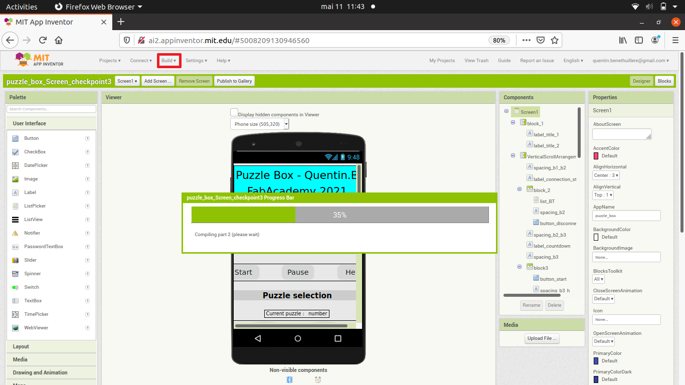
MIT App Inventor - Build application
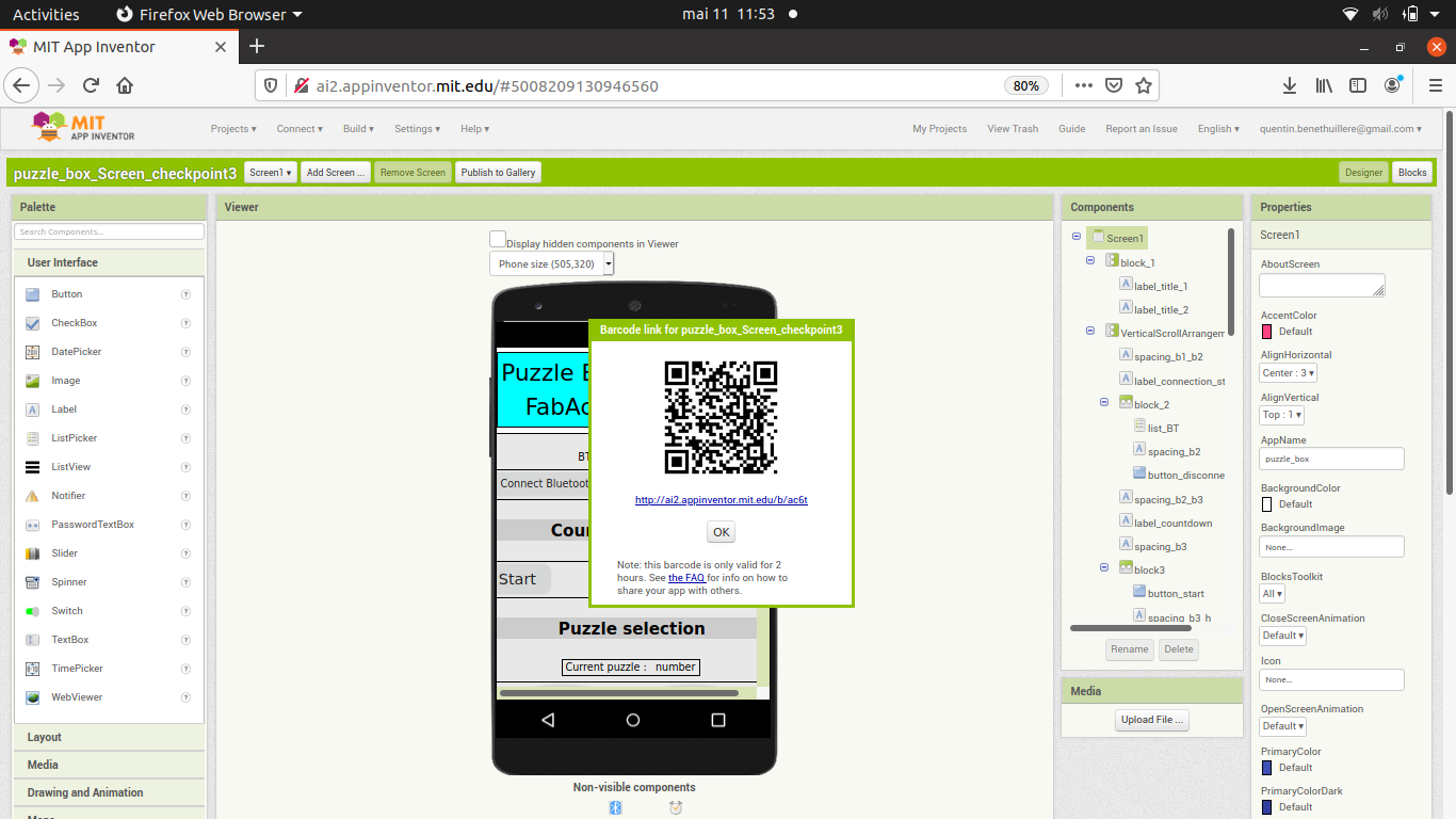
MIT App Inventor - QR code to install final application
After the application is installed on the phone, it can be used independently of the computer MIT App Inventor, and does not require any internet connection.
For looking at the final tests of my application, please refer to the video in the beginning of this section. This application will definitely be helpful for my puzzle box final project in the sense that it allows me to control from my phone several elements such as the countdown and the lock mechanisms.
Group Assignment
At the end of the week, we all have presented to the rest of the group the work we did, and the tools we used. For taking a look at the various solutions implemented, please refer to our dedicated group page.
Source Files
The source files of the work presented in this week assignment are available for download here :
- Phone application : MIT App Inventor project / APK
- Puzzle box mother board program : Arduino code / hex file
- Puzzle box daughter board program : Arduino code / hex file
- Puzzle box countdown program : Arduino code / hex file