8. Embedded programming
Assignments:
Individual assignments:
- Read a microcontroller data sheet.
- Program your board to do something, with as many different programming languages and programming environments as possible.
Group assignment:
- Compare the performance and development workflows for other architectures.
This week was the continuity of the electronic design week. As I had already managed to have my customized “Hello World + lock mechanism” board working at that time, I could focus this week on understanding the microcontrollers architectures, and programming my board with different programming languages : Arduino, C, Assembly.
Microcontrollers architectures
I have dedicated a lot of my time reading the first part of this “Make: AVR programming” book which deals with the programmation of AVR microcontrollers, digital inputs/outputs, the concept of bit twiddling, serial input/output, and analog to digital conversion. This was definitely helpful to understand the basics and get ready to put all this into practice.
At the end of the week, I have been through the ATtiny 45 datasheet, which is of course pretty hard to read, but from which I could understand quite important concepts with the knowledge I acquired with my previous readings / programming experiences. I chose to read the datasheet of this particular AVR microcontroller as it is the one that I fitted into my Hello World board.
The first pages of the datasheet are the most important ones as they give the main features of the microcontroller (ex: architecture type, program and data memories, number of pins and programmable Inputs/Outputs, operating voltage, power consumption, etc), as well as the pinout configuration.
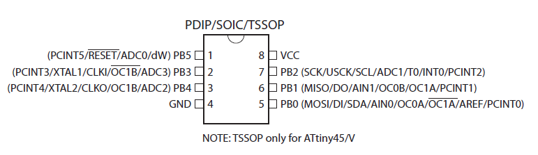
ATtiny25/45/85 pinout
And just to give an idea of how complex all this is, here below is presented the block diagram of the ATtiny45.
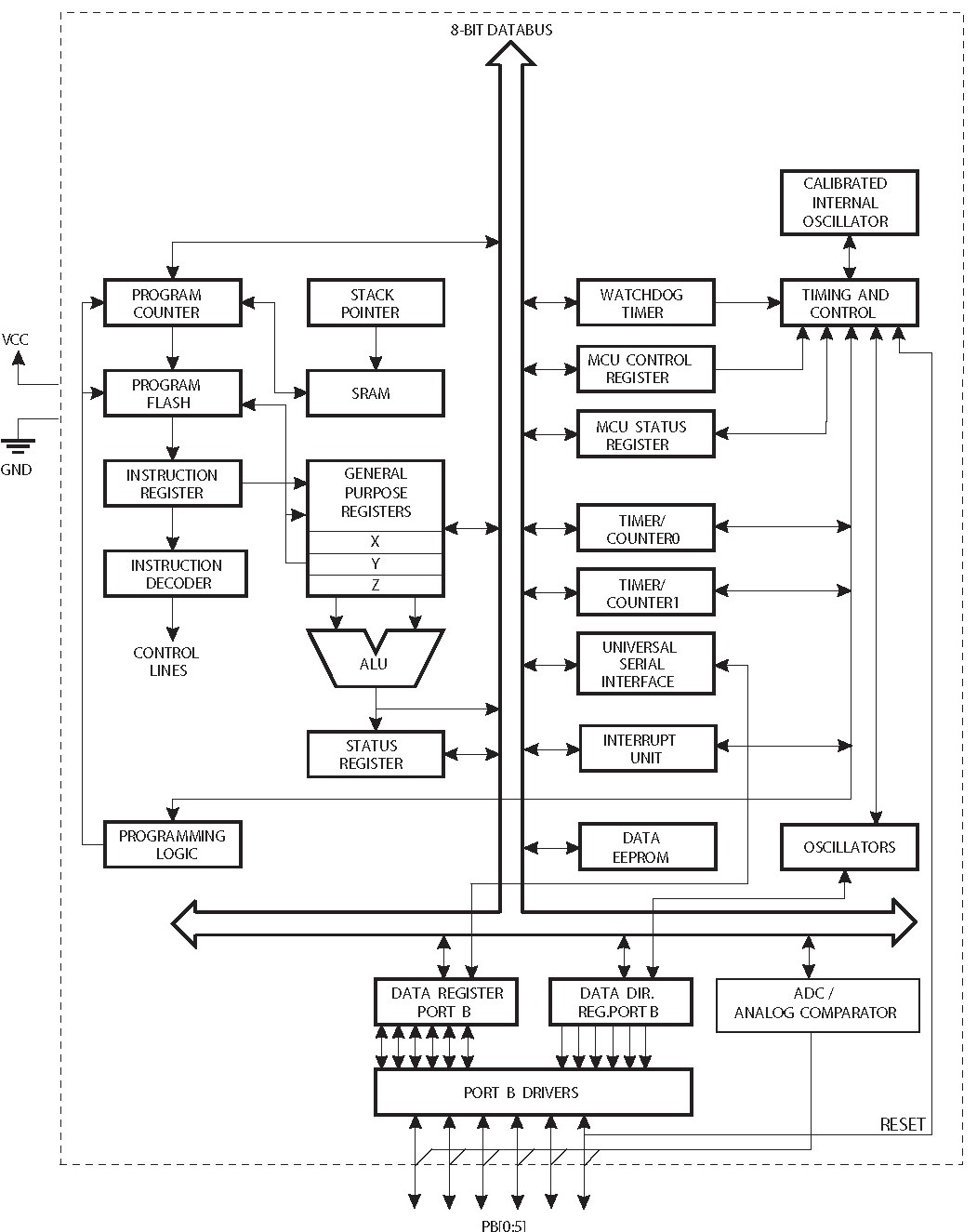
ATtiny25/45/85 block diagram
By going through this datasheet I got to know the following things :
- The ATtiny45 has three memory spaces : Data memory (volatile), Program memory (non volatile), and EEPROM Memory (non volatile) for data storage.
- The reset pin must be grounded for a certain minimum time to operate.
- The reset pin can also be used as a weak I/O pin.
- The 32 general purpose registers are directly connected to the Arithmetic Logic Unit (ALU) where all the calculations are performed.
- The ALU supports arithmetic and logic operations between registers or between a constant and a register, as well as single register operations.
- The Status Register contains information about the result of the most recently executed arithmetic instruction. This information can be used for altering program flow in order to perform conditional operations.
- The Stack is mainly used for storing temporary data, for storing local variables and for storing return addresses after interrupts and subroutine calls. The Stack Pointer Register always points to the top of the Stack.
- The AVR provides several interrupt sources.
- The AVR provides several clock sources (which by the way is quite complicated to understand).
- Each port pin consists of three register bits: DDxn, PORTxn, and PINxn.
- The DDxn bit in the DDRx Register selects the direction of this pin. If DDxn is written logic one, Pxn is configured as an output pin. If DDxn is written logic zero, Pxn is configured as an input pin.
- If PORTxn is written logic one when the pin is configured as an input pin, the pull-up resistor is activated. To switch the pull-up resistor off, PORTxn has to be written logic zero or the pin has to be configured as an output pin.
- If PORTxn is written logic one when the pin is configured as an output pin, the port pin is driven high (one). If PORTxn is written logic zero when the pin is configured as an output pin, the port pin is driven low (zero).
Lock mechanism programming
In this section I will present the codes that I wrote in different programming languages, to basically achieve the same functionality : controlling the opening of a lock mechanism with a push button. Note: In order to avoid damaging the 5V solenoid that I use as lock mechanism, all my tests were conducted first using a LED instead of the lock mechanism. This was quite easy to swap those 2 components as they connect to external pins of my PCB.
As a reminder, here is the PCB my programs are meant for :
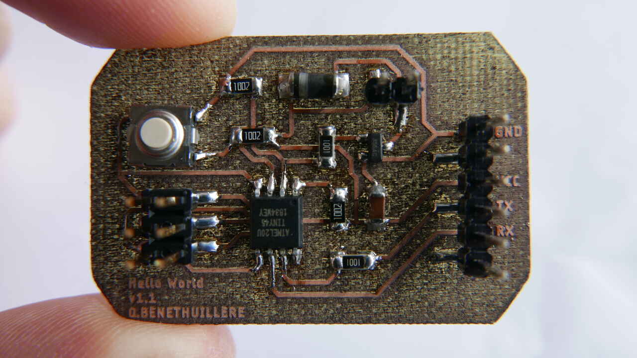
Hello world + lock mechanism PCB
For each programming language I basically ran into these 3 steps :
- Making a LED blink wihtout taking into account the push button status.
- Making the LED turn on (or the lock mechanism open) as long as the push button is pressed.
- Making the LED turn on (or the lock mechanism open) for a certain time following a push button pressed, and then forcing the LED off (or the lock mechanism closed) for a certain time before the push button can become effective again. This last test is the one that is closest to the real operation I want to achieve in my final project. The delay with lock mechanism open implemented after a push button press is to let some time for the user to open the previously locked compartment, and the inactivation delay that follows is simply to protect the lock mechanism solenoid from overheat.
Note: Based on the tests I performed, I observed that there was no need for debouncing the push button for my application. Nevertheless, I am aware that some applications require push buttons to be debounced, and I will have the opportunity to experiment with it in the near future.
Case 2 - video :
Case 3 - video :
This week I have not performed any additional test with the serial communication as I already covered it in this section of week 06. Also I will not go into details on how to flash a program into my ATtiny 45 as it has already been presented here.
Before you dive headfirst into my codes content which appears pretty raw in this website, let me present you how those codes appear in the Arduino IDE or using the Notepad++ editor. As you can see, some colors and indentation appear which make the development work much easier.
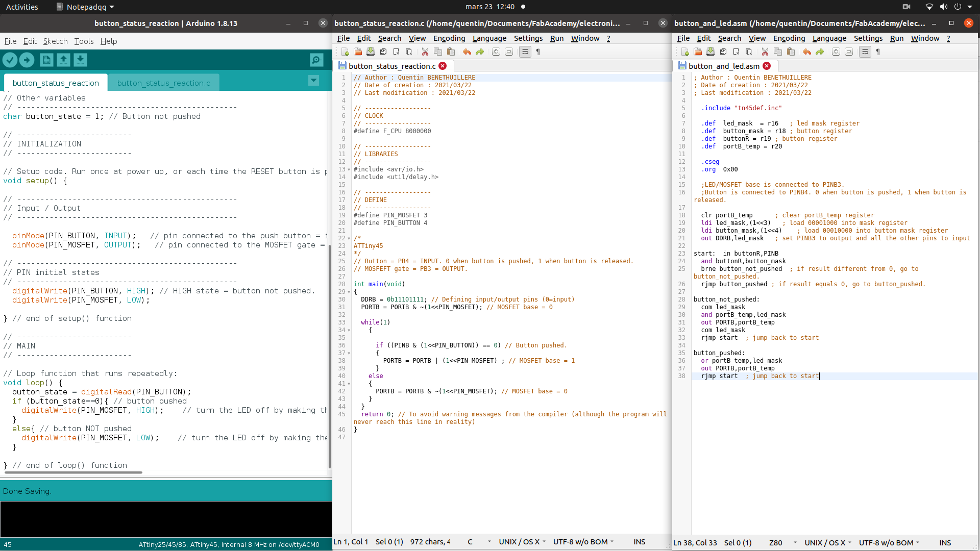
Code appearance - Arduino IDE (left), Notepad++ (center and right)
General Note
Using “define” instead of a normal variable allows to save program memory as those sort of variables are directly replaced by their value by the compiler when generating the .hex file.
Arduino
The Arduino language is a subset of C/C++, where you can also use assembly for ultra-low level code. An Arduino Sketch is associated to the Arduino IDE, which is basically a C/C++ compiler that generates machinecode for the Arduino boards. For additional information on the difference between C and Arduino, please refer to this website.
Prior to generating the compiled code (.hex) from the Arduino IDE, make sure that your configuration in the “Tools” menu is adapted to the microcontroller the code is intended to :
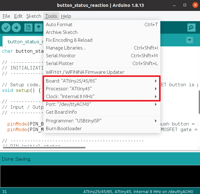
Arduino IDE config prior to exporting compiled binary
In order to make the ATtiny 45 microcontroller available in the board types of the Arudino IDE, I have followed the instructions given in this tutorial (section “Installing ATtiny support in Arduino 1.6.4”). The steps are the following in the Arduino IDE v1.8.13:
- Open “File -> Preferences”.
- In the “Additional Boards Manager URLs” field, copy paste the following link : “https://raw.githubusercontent.com/damellis/attiny/ide-1.6.x-boards-manager/package_damellis_attiny_index.json”.
- Click OK to validate the preferences.
- Close the Arduino IDE and open it again (this step might be optional).
- Open “Tools -> Board -> Boards Manager…”.
- Look for the attiny entry (at the very bottom of the list), click on it and start the install (if not already installed).
- Close the Boards Manager page, and now a category “ATtiny Microcontrollers” should be available in “Tools -> Board”, containing 2 entries : “ATtiny25/45/85” and “ATtiny24/44/84”.
Then, once your code is ready, export the compiled binary from the “Sketch” menu.
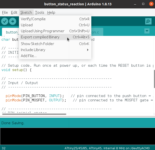
Arduino IDE - export compiled binary
1. Blink
// Author : Quentin BENETHUILLERE
// Date of creation : 2021/03/22
// Last modification : 2021/03/22

// the setup function runs once when you press reset or power the board
void setup() {
  #define ATTINY45_PIN_MOSFET 3
  pinMode(ATTINY45_PIN_MOSFET, OUTPUT);   // initialize ATTINY45_PIN_MOSFET as an output.
}

// the loop function runs over and over again forever
void loop() {
  digitalWrite(ATTINY45_PIN_MOSFET, HIGH);   // turn the MOSFET base to HIGH (LED on)
  delay(3000);                       // wait for X ms
  digitalWrite(ATTINY45_PIN_MOSFET, LOW);    // turn the MOSFET base to LOW (LED off)
  delay(3000);                       // wait for X ms
}
2. Output based on push button status
// Author : Quentin BENETHUILLERE
// Date of creation : 2021/03/22
// Last modification : 2021/03/22

/*
 * This program aims at activating a function (LED ON or lock mechanism open) as long as a push button is pressed on a customized version of an hello world board.
 */

// -------------------------
// DECLARATION OF DEFINES
// -------------------------

#define PIN_BUTTON 4 // Input pin connected to the push button.
#define PIN_MOSFET 3 // Output pin connected to the MOSFET gate.

// -------------------------
// DECLARATION OF VARIABLES
// -------------------------

// ------------------------------------------------
// Adjustable variables (program main parameters)
// ------------------------------------------------

// ------------------------------------------------
// PIN connections
// ------------------------------------------------

// ------------------------------------------------
// Other variables
// ------------------------------------------------
char button_state = 1; // Button not pushed

// -------------------------
// INITIALIZATION
// -------------------------

// Setup code. Run once at power up, or each time the RESET button is pressed:
void setup() {

// ------------------------------------------------
// Input / Output
// ------------------------------------------------

  pinMode(PIN_BUTTON, INPUT);   // pin connected to the push button = input.
  pinMode(PIN_MOSFET, OUTPUT);   // pin connected to the MOSFET gate = output.

// ------------------------------------------------
// PIN initial states
// ------------------------------------------------
  digitalWrite(PIN_BUTTON, HIGH); // HIGH state = button not pushed.
  digitalWrite(PIN_MOSFET, LOW);

} // end of setup() function

// -------------------------
// MAIN
// -------------------------

// Loop function that runs repeatedly:
void loop() {
  button_state = digitalRead(PIN_BUTTON);
  if (button_state==0){ // button pushed
    digitalWrite(PIN_MOSFET, HIGH);    // turn the LED off by making the voltage LOW
  }
  else{ // button NOT pushed
    digitalWrite(PIN_MOSFET, LOW);    // turn the LED off by making the voltage LOW
  }

} // end of loop() function
3. Output based on push button + time delays
// Author : Quentin BENETHUILLERE
// Date of creation : 2021/03/22
// Last modification : 2021/03/22

/*
 * This program aims at controlling a lock mechanism or a LED with a push button.
 * The idea is not that the lock mechanism is open as long as the button is pushed, but rather that the lock mechanism remains open for a certain time following the button push action, and then closes for a minimum time (to let the solenoid cool down).
 */

// -------------------------
// DECLARATION OF DEFINES
// -------------------------

#define PIN_BUTTON 4 // Input pin connected to the push button.
#define PIN_MOSFET 3 // Output pin connected to the MOSFET gate.
#define T_OPEN 3000 // Time (in ms) during which the lock will remain open (or LED will remain on) after a button push.
#define T_COOL_DOWN 5000 // Time (in ms) during which the it will not be possible to open the lock or to turn ON the LED after a button push. This is a protection to let the solenoid cool down. Normally it should not be powered more than 10 or 15 seconds.

// -------------------------
// DECLARATION OF VARIABLES
// -------------------------

// ------------------------------------------------
// Adjustable variables (program main parameters)
// ------------------------------------------------

// ------------------------------------------------
// PIN connections
// ------------------------------------------------

// ------------------------------------------------
// Other variables
// ------------------------------------------------
char button_state = 1; // Button not pushed

// -------------------------
// INITIALIZATION
// -------------------------

// Setup code. Run once at power up, or each time the RESET button is pressed:
void setup() {

// ------------------------------------------------
// Input / Output
// ------------------------------------------------

  pinMode(PIN_BUTTON, INPUT);   // pin connected to the push button = input.
  pinMode(PIN_MOSFET, OUTPUT);   // pin connected to the MOSFET gate = output.

// ------------------------------------------------
// PIN initial states
// ------------------------------------------------
  digitalWrite(PIN_BUTTON, HIGH); // HIGH state = button not pushed.
  digitalWrite(PIN_MOSFET, LOW);

} // end of setup() function

// -------------------------
// MAIN
// -------------------------

// Loop function that runs repeatedly:
void loop() {
  button_state = digitalRead(PIN_BUTTON);
  if (button_state==0){ // button pushed
    digitalWrite(PIN_MOSFET, HIGH);    // open the lock mechanism
    delay(T_OPEN);
    digitalWrite(PIN_MOSFET, LOW);    // close the lock mechanism
    delay(T_COOL_DOWN);
  }
  else{ // button NOT pushed
    digitalWrite(PIN_MOSFET, LOW);    // close the lock mechanism
  }

} // end of loop() function
C
In order to generate the .hex files from my C codes, I have used the Makefile presented below (of course the project name had to be modified in this Makefile depending on the code to be compiled).
PROJECT=button_solenoid_protection
SOURCES=$(PROJECT).c
MMCU=attiny45
F_CPU = 8000000

CFLAGS=-mmcu=$(MMCU) -Wall -Os -DF_CPU=$(F_CPU)

$(PROJECT).hex: $(PROJECT).out
    avr-objcopy -O ihex $(PROJECT).out $(PROJECT).c.hex;\
    avr-size --mcu=$(MMCU) --format=avr $(PROJECT).out

$(PROJECT).out: $(SOURCES)
    avr-gcc $(CFLAGS) -I./ -o $(PROJECT).out $(SOURCES)

program-bsd: $(PROJECT).hex
    avrdude -p t45 -c bsd -U flash:w:$(PROJECT).c.hex

program-dasa: $(PROJECT).hex
    avrdude -p t45 -P /dev/ttyUSB0 -c dasa -U flash:w:$(PROJECT).c.hex

program-avrisp2: $(PROJECT).hex
    avrdude -p t45 -P usb -c avrisp2 -U flash:w:$(PROJECT).c.hex

program-usbtiny: $(PROJECT).hex
    avrdude -p t45 -P usb -c usbtiny -U flash:w:$(PROJECT).c.hex

program-dragon: $(PROJECT).hex
    avrdude -p t45 -P usb -c dragon_isp -U flash:w:$(PROJECT).c.hex

program-ice: $(PROJECT).hex
    avrdude -p t45 -P usb -c atmelice_isp -U flash:w:$(PROJECT).c.hex
This code even allowed me to flash directly the compiled code into my ATtiny 45 microcontroller using the following command :
make program-usbtiny
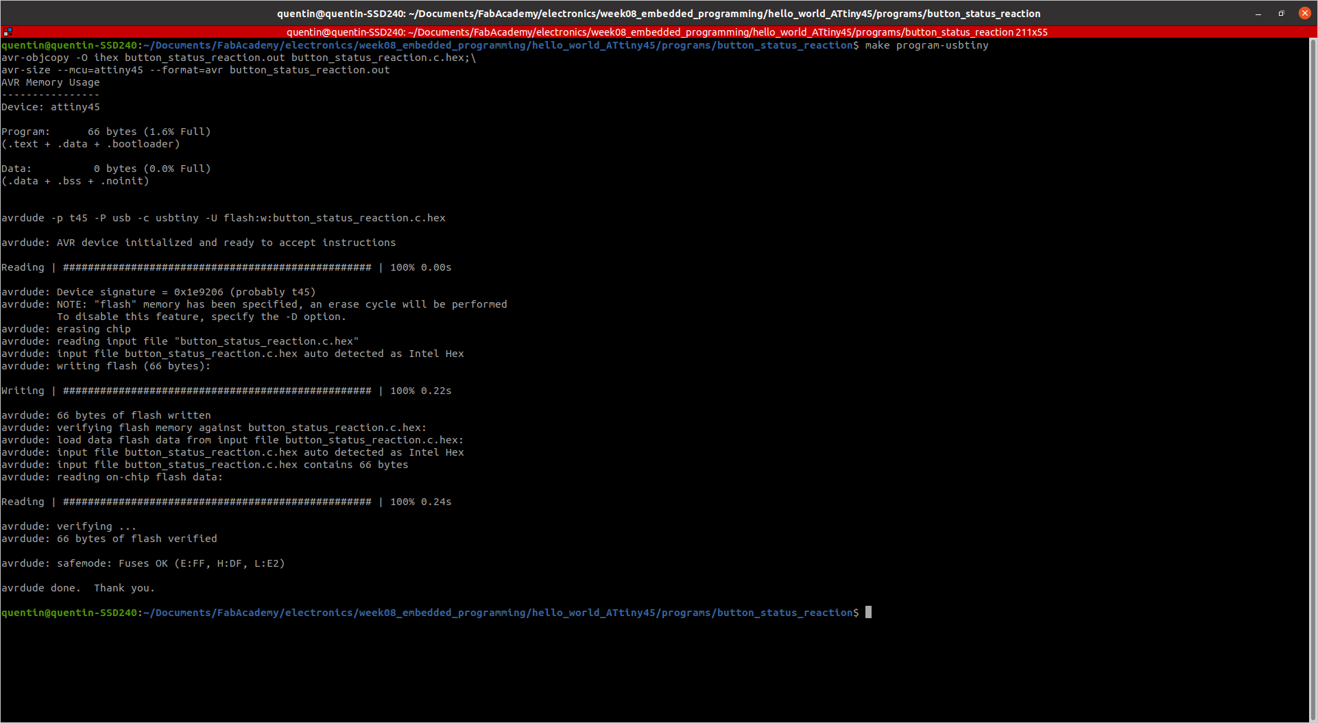
Compile and Flash program with Makefile
1. Blink
I will not present the simple blink code I tested in C, because all the interesting information can be found in the little more complex codes presented hereafter.
2. Output based on push button status
// Author : Quentin BENETHUILLERE
// Date of creation : 2021/03/22
// Last modification : 2021/03/22

// ------------------
// CLOCK
// ------------------
#define F_CPU 8000000

// ------------------
// LIBRARIES
// ------------------
#include <avr/io.h>
#include <util/delay.h>

// ------------------
// DEFINE
// ------------------
#define PIN_MOSFET 3
#define PIN_BUTTON 4

/*
ATTiny45
*/
// Button = PB4 = INPUT. 0 when button is pushed, 1 when button is released.
// MOSFEFT gate = PB3 = OUTPUT.

int main(void)
{
    DDRB = 0b11101111; // Defining input/output pins (0=input)
    PORTB = PORTB & ~(1<<PIN_MOSFET); // MOSFET base = 0

    while(1)
        {

        if ((PINB & (1<<PIN_BUTTON)) == 0) // Button pushed.
        {
                PORTB = PORTB | (1<<PIN_MOSFET) ; // MOSFET base = 1
            }
        else
        {
            PORTB = PORTB & ~(1<<PIN_MOSFET); // MOSFET base = 0
        }
    }
    return 0; // To avoid warning messages from the compiler (although the program will never reach this line in reality)
}
Important things to note here :
- DDRB : Port B Data Direction Resigster that configures pins as inputs (0) or outputs (1) - read/write.
- PORTB : Port B Data Register that configures output to low level (0) or high level (1) - read/write.
- PINB : Port B Input Pins Register that reads input; low level (0), high level (1) - read only.
Also the concept of mask is very convenient for bit twiddling purposes. For more information on bit twiddling please refer to chapter 4 of “Make: AVR programming” book. Herebelow a few examples of masks :
- 1<<0 = 0b00000001
- 1<<1 = 0b00000010
- …
- 1<<6 = 0b01000000
- 1<<7 = 0b10000000
Combined with bitwise operators such as AND (&), OR (|), NOT (~), XOR (^), this allows to manipulate bits one by one if desired.^
3. Output based on push button + time delays
// Author : Quentin BENETHUILLERE
// Date of creation : 2021/03/22
// Last modification : 2021/03/22

// ------------------
// CLOCK
// ------------------
#define F_CPU 8000000

// ------------------
// LIBRARIES
// ------------------
#include <avr/io.h>
#include <util/delay.h>

// ------------------
// DEFINE
// ------------------
#define PIN_MOSFET 3 // Input pin connected to the push button.
#define PIN_BUTTON 4 // Output pin connected to the MOSFET gate.
#define T_OPEN 3000 // Time (in ms) during which the lock will remain open (or LED will remain on) after a button push.
#define T_COOL_DOWN 5000 // Time (in ms) during which the it will not be possible to open the lock or to turn ON the LED after a button push. This is a protection to let the solenoid cool down. Normally it should not be powered more than 10 or 15 seconds.

/*
ATTiny45
*/
// Button = PB4 = INPUT. 0 when button is pushed, 1 when button is released.
// MOSFEFT gate = PB3 = OUTPUT.

int main(void)
{
    DDRB = 0b11101111; // Defining input/output pins (0=input)
    PORTB = PORTB & ~(1<<PIN_MOSFET); // MOSFET base = 0

    while(1)
        {

        if ((PINB & (1<<PIN_BUTTON)) == 0) // Button pushed.
        {
                PORTB = PORTB | (1<<PIN_MOSFET) ; // MOSFET base = 1
                _delay_ms(T_OPEN);
                PORTB = PORTB & ~(1<<PIN_MOSFET); // MOSFET base = 0
                _delay_ms(T_COOL_DOWN);
            }
        else
        {
            PORTB = PORTB & ~(1<<PIN_MOSFET); // MOSFET base = 0
        }
    }
    return 0; // To avoid warning messages from the compiler (although the program will never reach this line in reality)
}
Assembly
Programming in Assembly language allows to fully optimize code for any situation and write programs that do exactly what you want, with no compiler in the middle trying to interpret what you mean. Thus, learning Assembly gives you full transparency to your program. In order to produce a .hex output file that can run on a microcontroller, the assembly source code must be passed through an assembler specific to the chip’s architecture. Unlike compilers which may produce different outputs when given the same source code, assemblers essentially perform a one to one translation of instruction mnemonics and operands into machine code. All assemblers should produce the same output when given the same source code. The main difference between assemblers is their support for various directives and the development environments they offer.
Assembly language was brand new to me, and as a start I have been through various presentations and tutorials. Personnaly speaking, I felt that this tutorial was a really good introduction to Assembly language and allowed me rather quickly to have my first simple program running. Also I had to retrieve a library dedicated to the ATtiny 45 in this website.
Although I found it very interesting to discover this programming language it is definitely not the easiest one to use as a beginner.
As I am working on Linux environment I have decided to use AVRA assembler. In order to generate the .hex file from the .asm assembly code, I simply had to run the following command :
avra <program_name.asm>
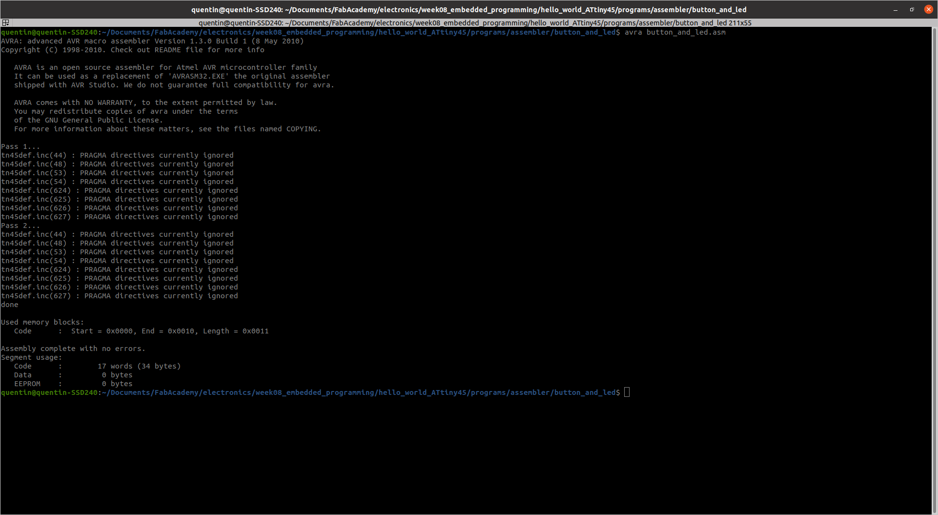
Generating .hex file with Avra assembler
1. Blink
; Author : Quentin BENETHUILLERE
; Date of creation : 2021/03/22
; Last modification : 2021/03/22

  .include "tn45def.inc"

    .def    mask    = r16       ; mask register
    .def    ledR    = r17       ; led register
    .def    oLoopR  = r18       ; outer loop register
    .def    iLoopRl = r24       ; inner loop register low
    .def    iLoopRh = r25       ; inner loop register high

  .equ  oVal    = 71 ; outer loop value.
    .equ    iVal    = 28168     ; inner loop value
    ; The values chosen for the previous constants will give about 1 second delay between each LED state change.

    .cseg
    .org    0x00

    ;LED is connected to PINB3.

    clr ledR            ; clear led register
    ldi mask,(1<<3)     ; load 00001000 into mask register
    out DDRB,mask       ; set PINB3 to output

start:  eor ledR,mask       ; toggle PINB3 in led register
    out PORTB,ledR      ; write led register to PORTB

    ldi oLoopR,oVal     ; initialize outer loop count

oLoop:  ldi iLoopRl,LOW(iVal)   ; intialize inner loop count in inner
    ldi iLoopRh,HIGH(iVal)  ; loop high and low registers

iLoop:  sbiw    iLoopRl,1       ; decrement inner loop registers
    brne    iLoop           ; branch to iLoop if iLoop registers != 0

    dec oLoopR          ; decrement outer loop register
    brne    oLoop           ; branch to oLoop if outer loop register != 0

    rjmp    start           ; jump back to start
2. Output based on push button status
; Author : Quentin BENETHUILLERE
; Date of creation : 2021/03/22
; Last modification : 2021/03/22

    .include "tn45def.inc"

    .def    led_mask    = r16       ; led mask register
    .def    button_mask = r18   ; button register
    .def    buttonR = r19   ; button register
    .def    portB_temp = r20

    .cseg
    .org    0x00

  ;LED/MOSFET base is connected to PINB3.
    ;Button is connected to PINB4. 0 when button is pushed, 1 when button is released.

    clr portB_temp          ; clear portB_temp register
    ldi led_mask,(1<<3)     ; load 00001000 into mask register
    ldi button_mask,(1<<4)      ; load 00010000 into button mask register
    out DDRB,led_mask       ; set PINB3 to output and all the other pins to input

start:  in buttonR,PINB
    and buttonR,button_mask
    brne button_not_pushed  ; if result different from 0, go to button_not_pushed.
    rjmp button_pushed ; if result equals 0, go to button_pushed.

button_not_pushed:
    com led_mask
    and portB_temp,led_mask
    out PORTB,portB_temp
    com led_mask
    rjmp start  ; jump back to start

button_pushed:
    or portB_temp,led_mask
    out PORTB,portB_temp
    rjmp start  ; jump back to start
3. Output based on push button + time delays
By lack of time I could unfortunately not generate this last program. And as can be seen from the blink example, it is not that straightforward in Assembly to deal with delay functions. For further information I recommend to refer to the section “Calculating delay time” of the tutorial mentioned in introduction of this chapter about Assembly. Briefly, it requires to know how many clock cycles each instruction take to determine how many loops must be performed in the code to reach the desired delay.
Source files
The source files of the work presented in this week assignment are available for download here :