2. Computer-aided design
Assignments:
- Model (raster, vector, 2D, 3D, render, animate, simulate, …) a possible final project.
- Compress your images and videos and post them on your class page.
3D modelling
Freecad - final project design
This week I have mainly worked on creating a first draft 3D design of my final project. In order to know more about my final project, please refer to the dedicated section or at the time being to my first assignment.
Below is the result of what I have managed to achieve using the open-source Freecad software :
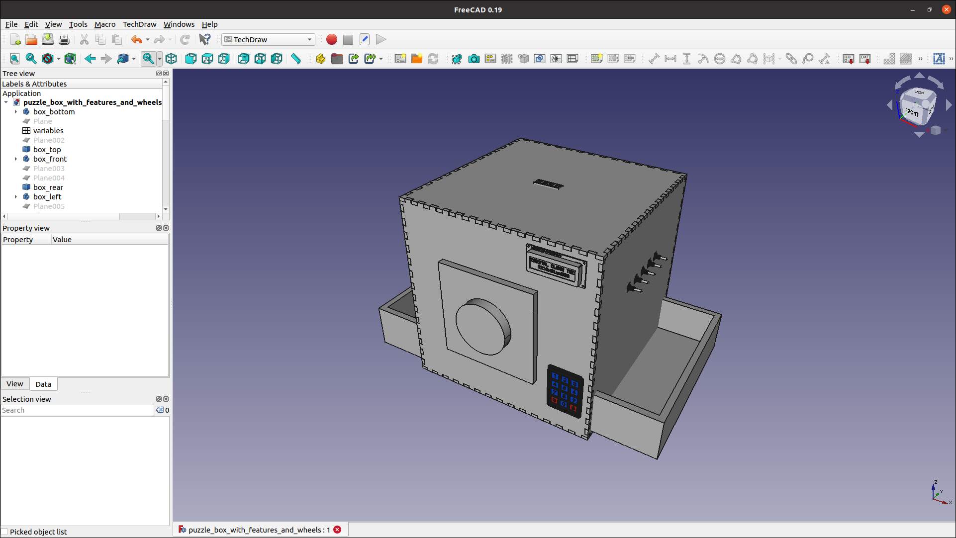
Puzzle box - front top right view - 2021/02/09
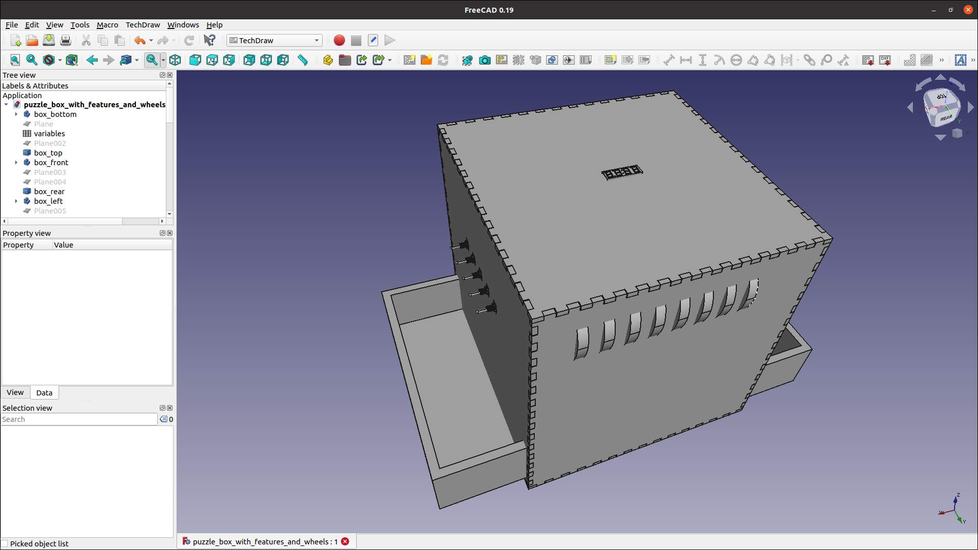
Puzzle box - rear top left view - 2021/02/09
Source file is available here : Puzzle box - Freecad model (Note: this file has been generated with FreeCAD 0.19 and thus cannot be opened with Freecad 0.18)
Before starting with this software which was entirely new to me, I have watched several videos on Invent Box Tutorials. This was in my opinion a really good introduction to Frecad.
Press fit box creation
In order to realize the main frame, which is a press fit box, I could have used the BoxCreator add-on, but unfortunately it was not working with my environment. As a result I made the whole box design myself. Here are the main steps I followed :
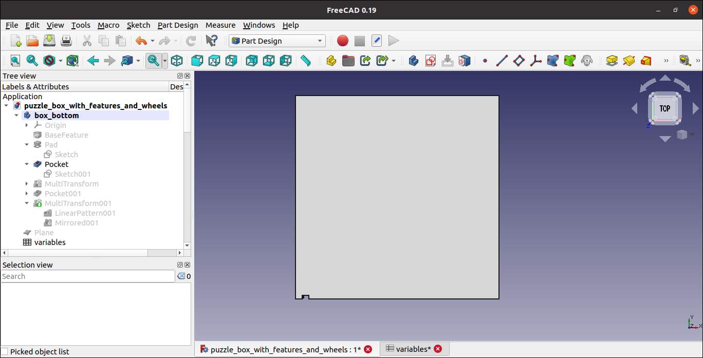
1- Design of a simple square plate :
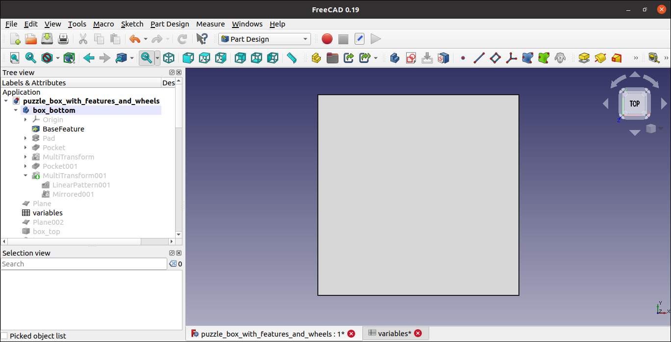
Box bottom plate - top view
2- Draw a 2D Sketch of one notch :
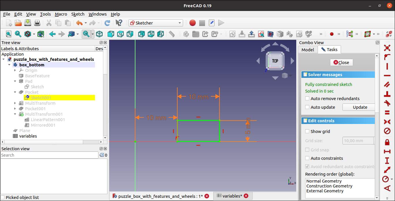
Box bottom plate - 2D notch sketch
3- Generate a pocket in the plate using the notch sketch :
Box bottom plate with one notch - top view
4- Replicate the notch using linear and mirroring tools :
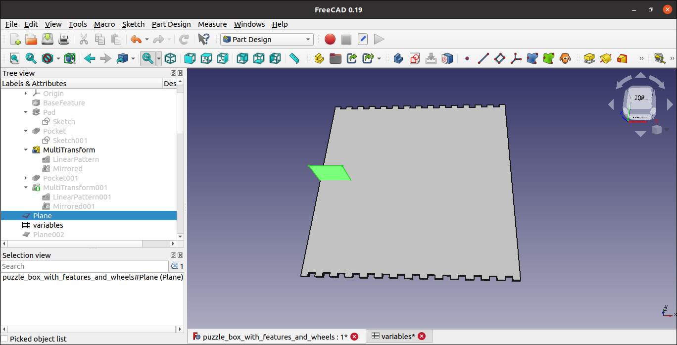
Box bottom plate with notches replicated over 2 sides - top view
Note : the green object in the image above is the construction plane that was used for the mirroring action.
5- Perform steps 2/3/4 in order to create notches on the 2 remaining sides :
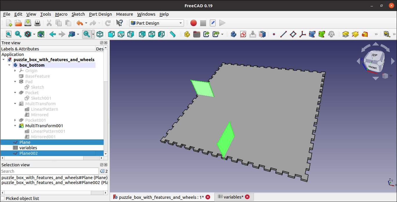
Box bottom plate completed - top view
Note : the green objects in the image above are the construction planes that were used for the mirroring actions.
6- Create the other faces of the box using the same methodology and using the rotation and translation tools.
Notes : the faces can be copied identically for each set of 2 opposite faces.
Parametric design
In order to make my box easily adjustable in terms of dimension, I conducted a parametric design with the use of variables. In the exmple below I demonstrate how the bottom plate is automatically adjusted based on the dimension parameters chosen.
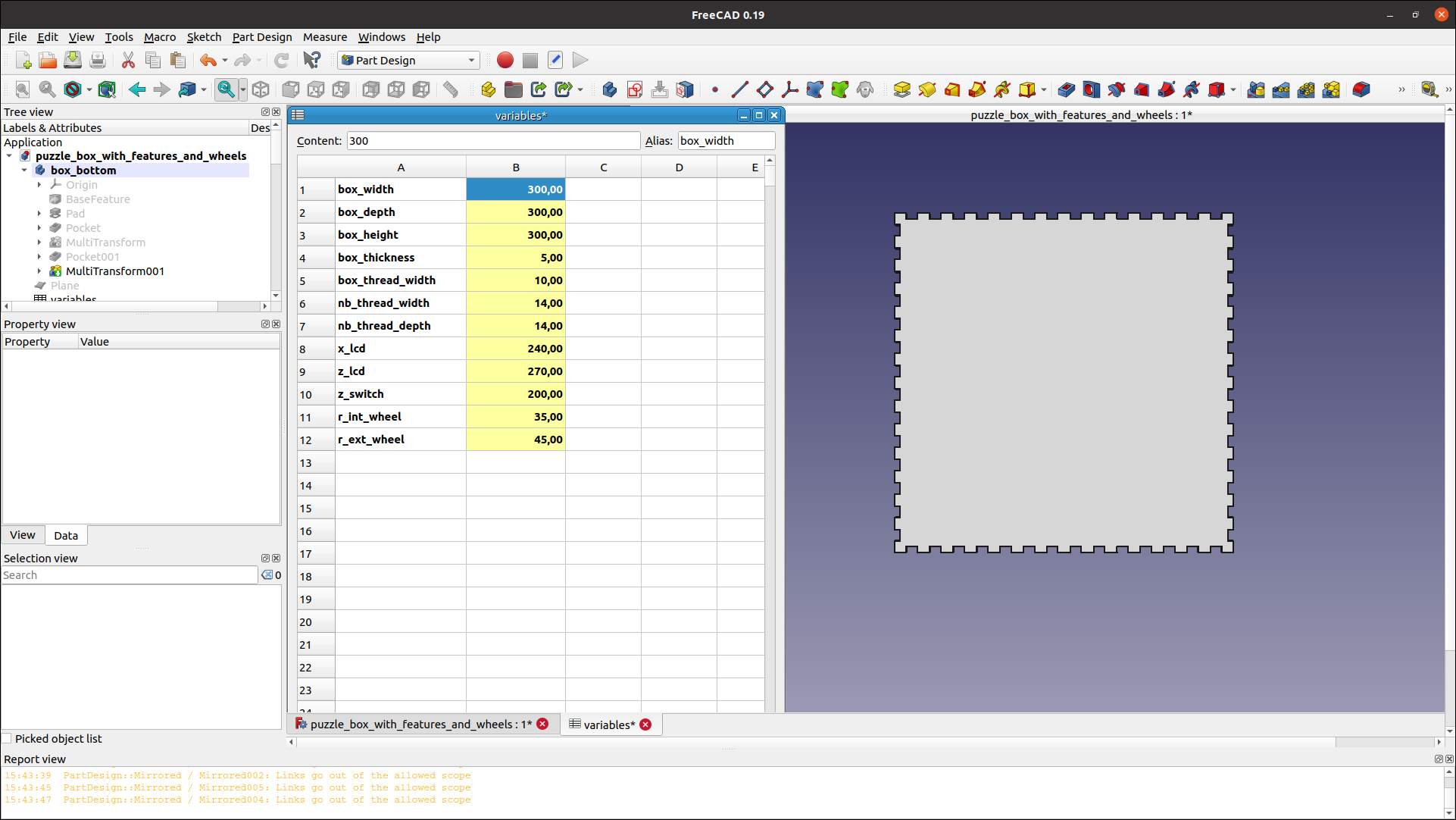
Box bottom plate - 300mm width - top view
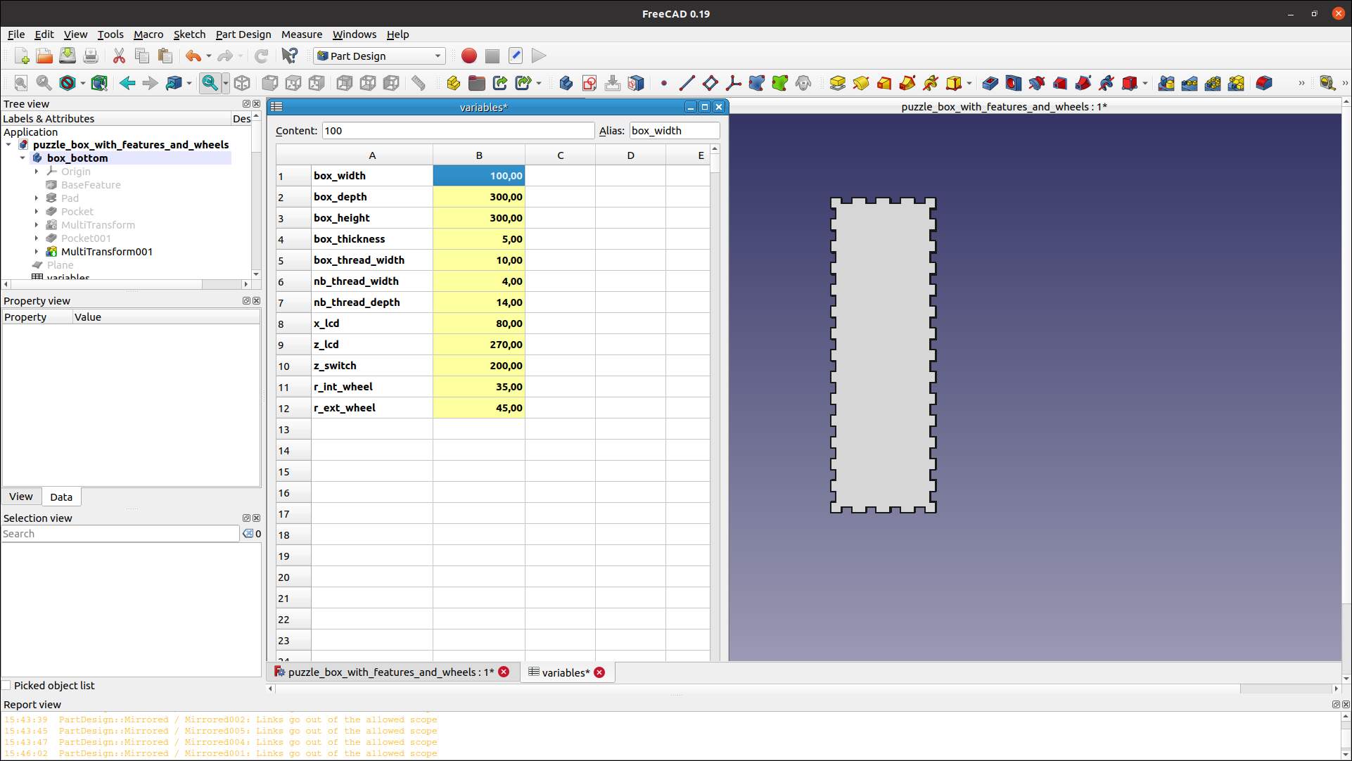
Box bottom plate - 100mm width - top view
Electronics components
All the electronic components that can be seen on my design (LCD, 4 digits display, keypad and switches), have been downloaded as “.step” files on grabcad, and then I imported them in my Freecad project.
OpenSCAD
I have performed some tests using OpenSCAD which is also a free, open-source software, but which offers a completely different approach of 3D design compare to most of the CAD software. Modelling in openSCAD is performed with command lines, and manipulating basic 3D objects such as parallelepipeds, spheres, cylinders, cones. The whole idea is to combine those objects using translation, rotation, as well as union and difference in order to achieve modelling. The usage of variables in rather straight forward in this software, which is much appreciated.
This time I modelled the structure of a Kyrgyz Yurt, the idea coming from a recent trip I did there. For the ones who have never heard of it, this is a really symbolic traditional house for nomades of Central Asia, to such an extent that Kyrghyztan uses this symbol in their national flag. See picture below before looking at the model.
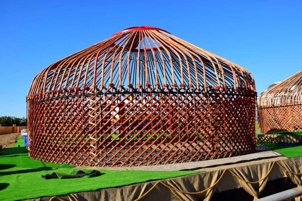
Yurt - Traditional house in Central Asia
And here is the result of my modelling using OpenSCAD :
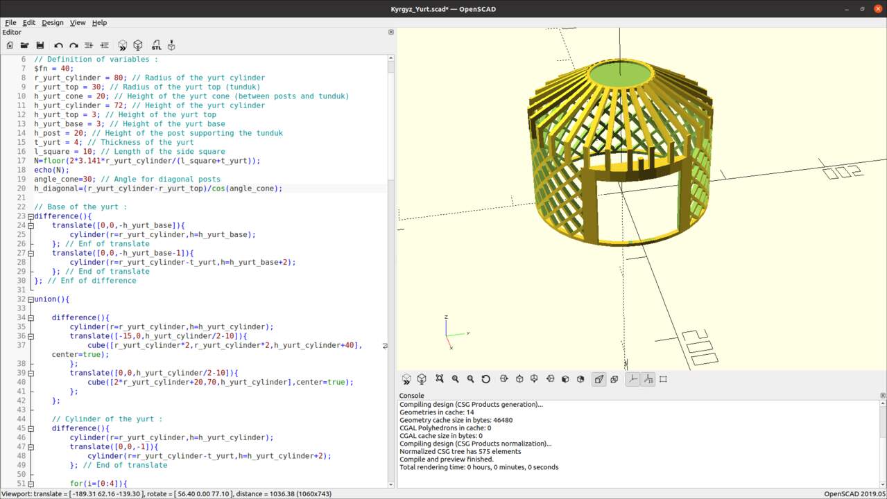
Kyrgyz Yurt - OpenSCAD modelling
Source file is available here : Kyrgyz yurt - OpenSCAD model
As I explained briefly in the introduction of this section, the point is to create simple objects and combine them in order to create the desired 3D object. As an example, in order to create a “ring” the idea is to create a first cylinder, and then a second cylinder with a smaller diameter. The second cylinder can then be sustracted easily from the first one, resulting in a simple ring shape. Such a manipulation and the corresponding code (whiwh was used to generate the base of the yurt model presented above) can be seen in the screenshot below :
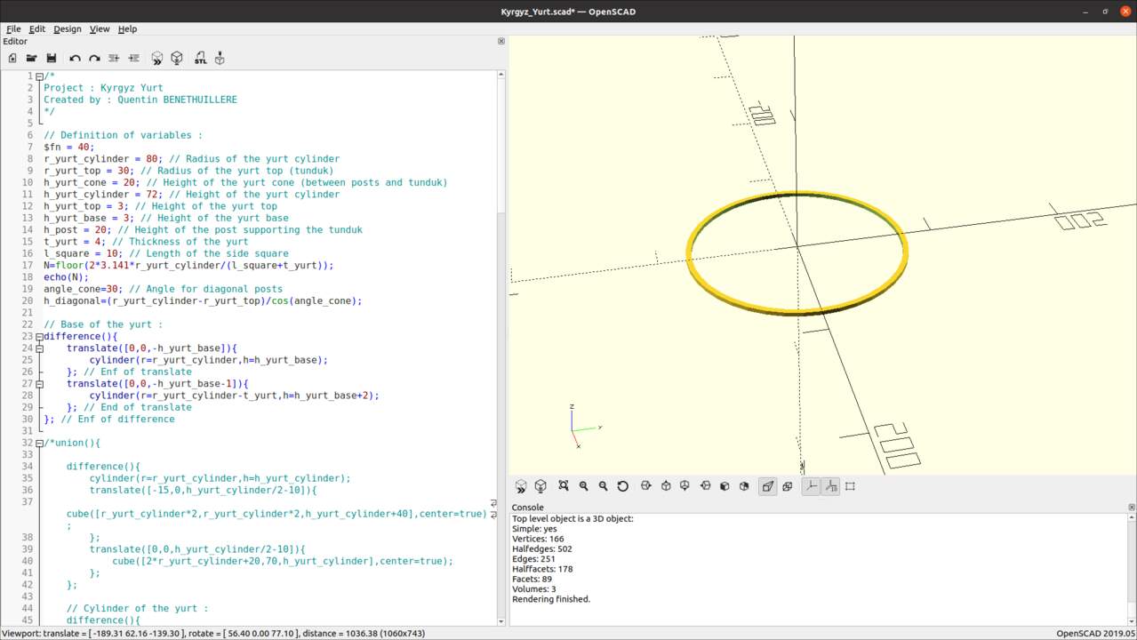
Creating a “ring” - OpenSCAD modelling
Fusion 360
Even though Fusion 360 is a licensed SW, I wanted to give it a try because it seems to be very powerful and complete. Here below some screenshots of a lead I designed as a replacement part for my bike. The idea would then be to print this part using 3D printing later during this class.
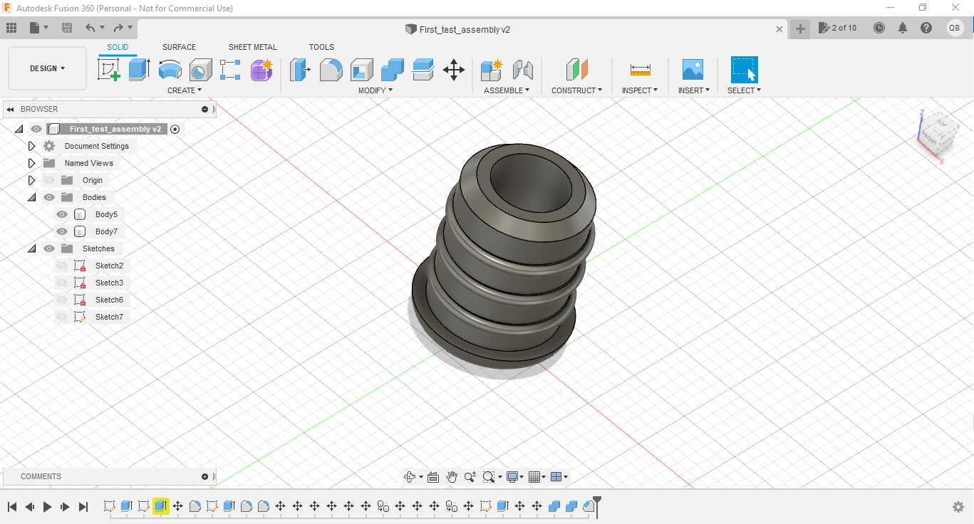
Bike lead designed with Fusion 360 - inside view
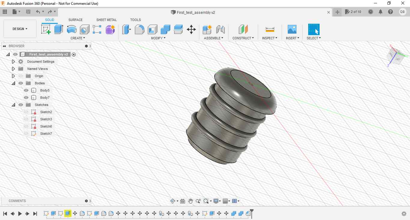
Bike lead designed with Fusion 360 - external view
And I gave a short try to the rendering feature which offers a lot of possibility. Unfortunately I had no enough time to deep dive into it yet.

Bike lead designed with Fusion 360 - rendering
Source file is available here : Bike lead - Fusion360 model
2D modelling
Inkscape
Inkscape is a free, open-source vector graphics editor used to create vector images. The most common format for those files is “.svg” which stands for “Scalable Vector Graphics”. The main interest in vector images is that it can be zoomed in as far as you want, the image will never pixelized.
Importing files from other CAD tools
First intersting thing is that it is possible to open in Inkscape files with .svg format exported from a projection of 3D objects designed in other CAD tools. As a demonstration, you can see below in Inkscape the bottom plate that I designed in 3D in Freecad software.
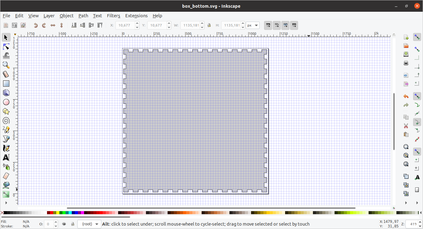
Box bottom plate imported in Inkscape after design in Freecad
I thought it would be possible to use this imported object and to merge it with other drawings directly made in Inkscape but I have not managed to do so yet.
Drawing directly in Inkscape
In order to get familiar with the software I have designed simple shapes, likes different sort of gears that could be used for my puzzle box final project.
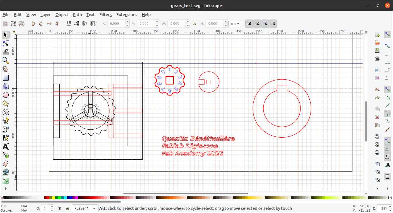
Inkscape drawings
And below a considerable zoom in one element of previous drawing demonstrating the image never gets pixelized.
Inkscape image zoomed in - never gets pixelized
This software offers a lot of possibilities in terms of drawing, and also allows to write texts as well. It will definitely be helpful for the different elements I want to engrave on the components of my box, such as this world map below that I downloaded on the internet :
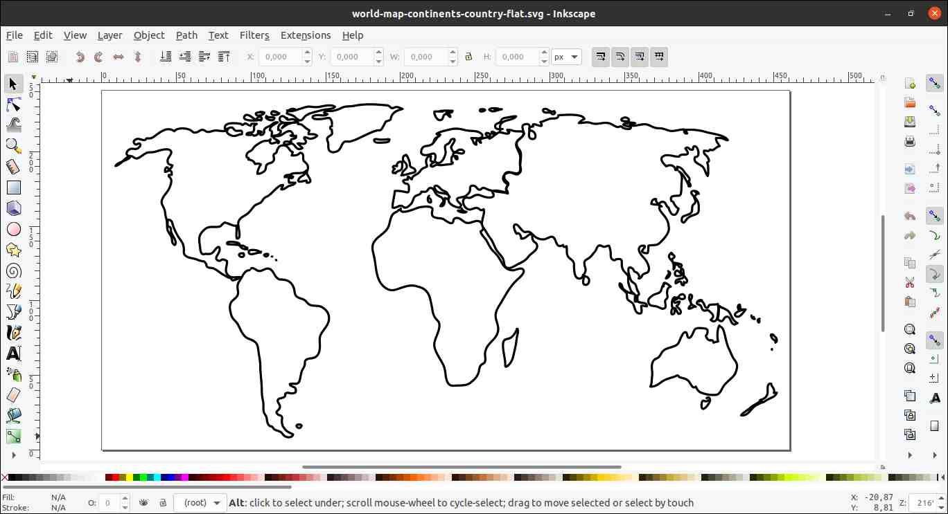
Vector drawing of the world map
Source files
The source files of the work presented in this week assignment are available for download here :
- Puzzle box - Freecad model (Note: this file has been generated with FreeCAD 0.19 and thus cannot be opened with Freecad 0.18)
- Kyrgyz yurt - OpenSCAD model
- Bike lead - Fusion360 model / Bike lead .STEP