5. 3D scanning and printing
Assignments:
Individual assignments:
- Design and 3D print an object (small, few cm3, limited by printer time) that could not be made subtractively.
- 3D scan an object (and optionally print it).
Group assignment:
- Test the design rules for your 3D printer(s).
3D scanning
3D laser scanning is a way to capture a physical objects exact size and shape into the computer world as a digital 3-dimensional representation. A single scan is not enough to re-create a complete model of the object being scanned. Normally, hundreds of scans are necessary to capture all of the information from various sides and angles. All of these scans then have to be integrated through a common reference system known as alignment or registration. Finally, the individual scans are merged to re-create the final model.
The main 3D scanning technologies are the following :
- Laser triangulation 3D scanning : laser line(s) is/are projected onto the object, sensor(s) capture the reflection and the shape of the object is computed based on the line(s) deformations.
- Structured light 3D scanning technology : similar to laser triangulation, but this time light pattern (consisting of bars, blocks, or other shapes) are used instead of lines.
- Photogrammetry : computation of the 3D shape based on the combination of multiple photographies of the object from different angles.
- Contact-based 3D scanning technology : a probe is physically in contact with the object and moved around it.
- Laser pulse-based 3D scanning technology : measures the time between the emission of a laser signal and the reception of its reflection, and uses the speed of light to compute the object shape.
Scanning with EinScanPro+
Before goig any further, I would like to thank my colleague Ambroise De Vries who shared his real expertise on 3D scanning with the rest of the group. On that occasion, he gave us an introduction with the material he is familiar with : the 3D scanner EinScanPro+ of Shining 3D company and its proprietary EinScan software. He also brought a turntable so that we could try both handled and fixed scan.
This 3D scanner offers 4 modes of scan using structured light :
- Handheld rapid Scan
- Handheld HD Scan
- Fixed scan without turntable
- Fixed scan with turntable
Fixed scan with turntable
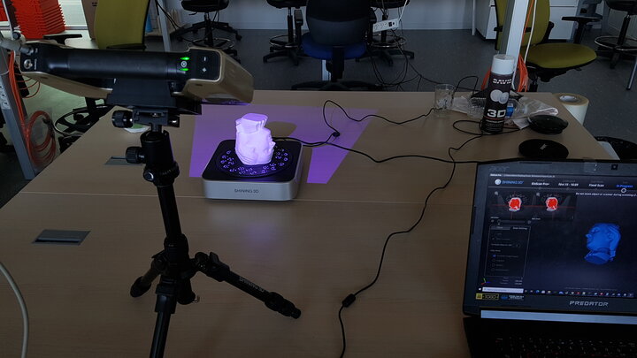
We started with a fixed scan with turntable of a 3D printed Mozart. In order to do so the 3D scanner was fixed on a tripod, and the object to be scanned was placed on the turntable at a distance of about 50cm from the scanner as presented below.
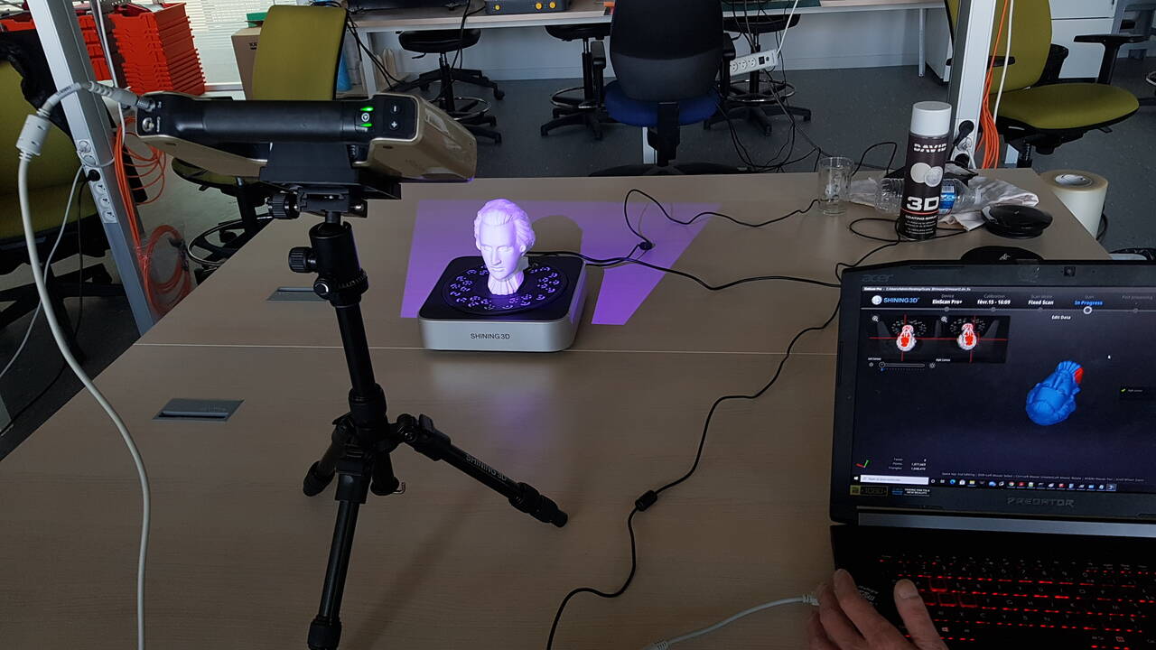
3D scanning setup - Automated mode
 |
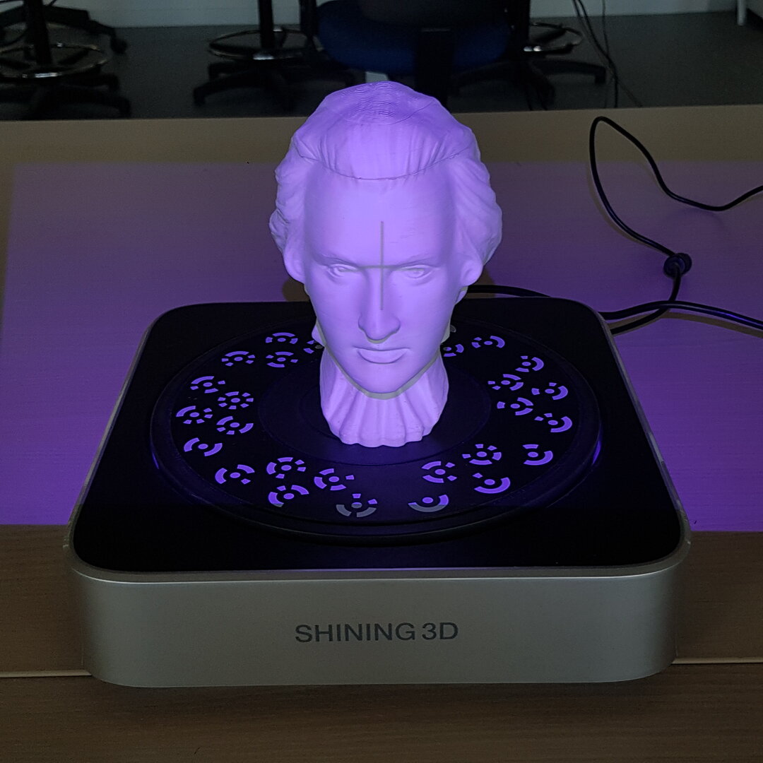 |
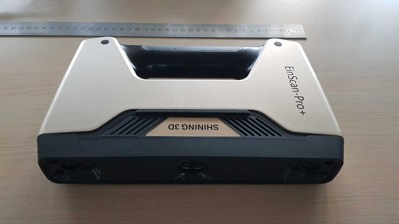
| Shining 3D - EinScanPro+ scanner | Mozart model - 3D printed |
Here are the steps that we followed for performing the fixed scan with turntable :
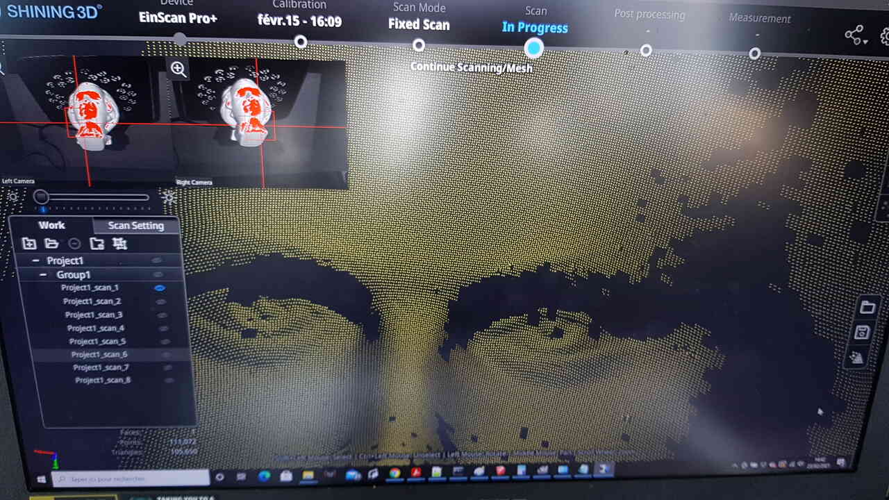
1 - In the software, we set to 8 the number of scanning angular positions. After scanning a given position, the turntable automatically rotated to the next position which thus presented a different angle of the object to the scanner.
Following this first phase, we obtained on the software a resentatation of the model with millions of points in space which is called a points cloud. However, as it is easily understandable, at this stage we still have areas of the model which have not been scanned. Those shadowed areas appear in yellow in the right side image hereunder.
 |
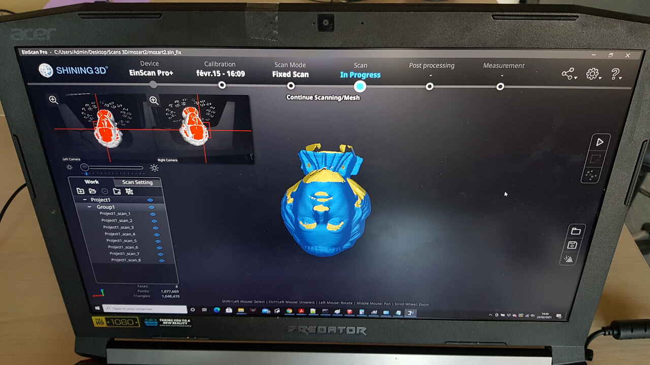 |
| 3D scanning - points cloud | Model after first scan (yellow = shadowed areas) |
2 - Flipped the Mozart model upside down (which was facilitated by the fact that the 3D printed model was scalped :)), and performed another scanning on 8 angular positions with the turntable. At this stage, the model is quite complete but there are still some parts missing as will be seen later.
Mozart model scanned upside down
Note : For each points cloud obtained, we performed a cleaning action to delete artefact points in order to obtain better results in the next step. However I do not have any picture to provide for this step.
3 - Performed the alignment / registration of the model, which consists in mapping the different sequences of point clouds obtained, and making a 3D model out of it. Here two options are possible, either making a watertight model or an unwatertight model. The first option directly gives a 3D model without any hole, which means that even if some parts of the object are missing after the scanning process the software will manage to fill them automatically. Depending on the object scanned and the quality of the scan, this can give sufficient result. For the exercice we chose to create an unwatertight model, and thus we obtained a model with holes where there were not enough points scanned (yellow areas in the image below on the left side). Points are connected so as to make triangles as can be seen when zooming in the model (see right side image below), this is called triangularization.
 |
 |
| Mozart model after registration (yellow areas = holes) | Triangles revealed when zooming in the model |
Mozart model after registration (yellow areas = holes)
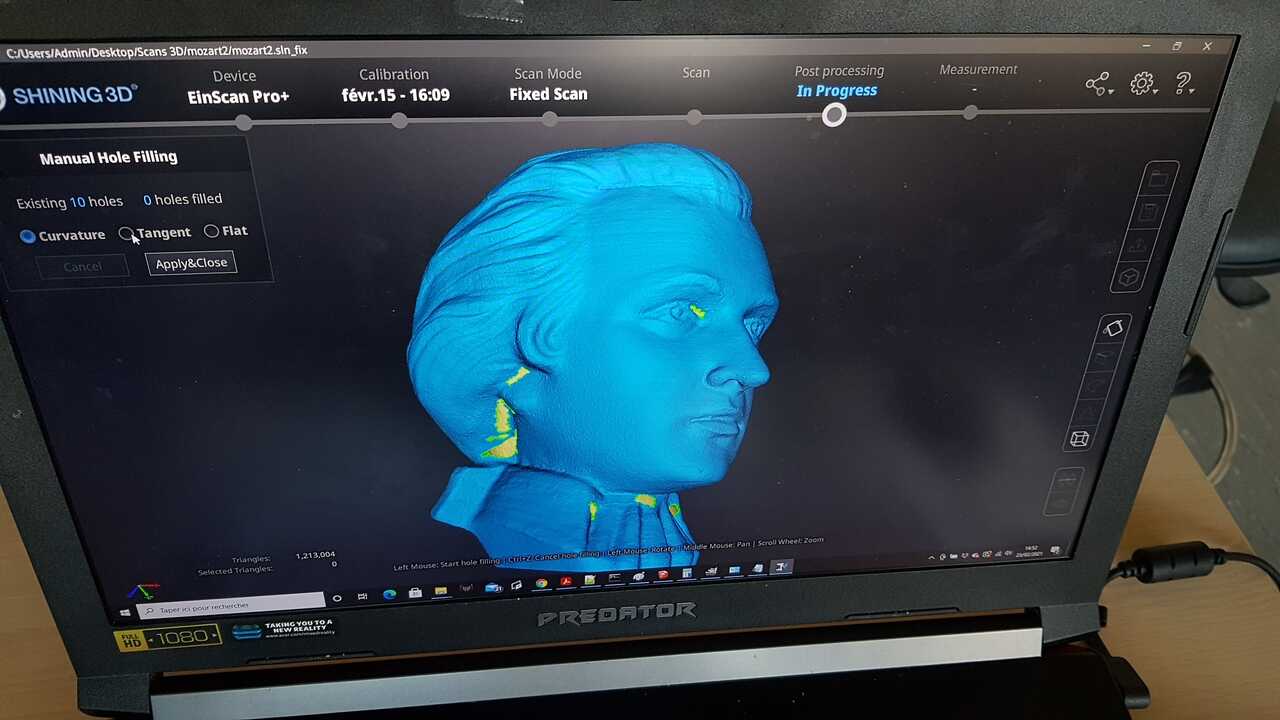
4 - Next step was to fill the holes. Several options are offered for doing so, and different treatment can be applied to the different holes. Indeed in some location, a flat filling might be sufficient whereas in other location a curve filling may be more appropriate. Here is a picture of the model obtained after all the holes had been filled to make the model watertight.
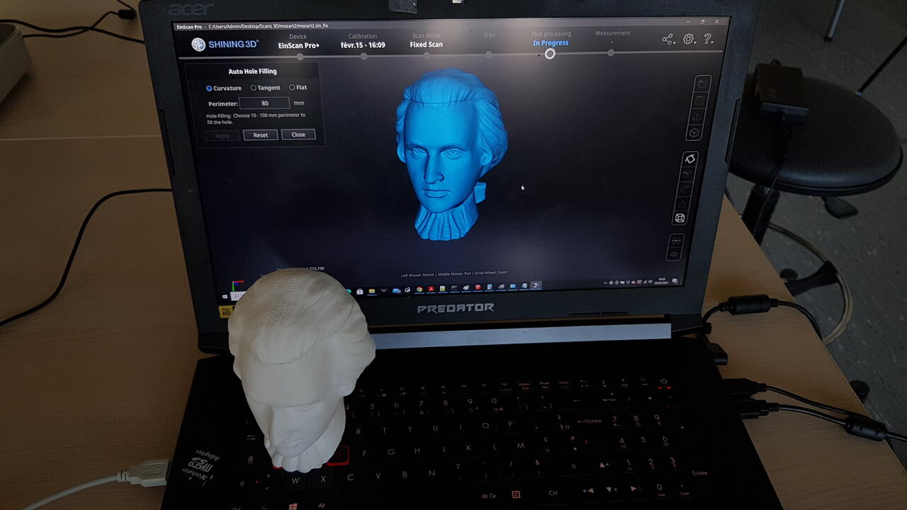
Final Mozart model
5 - Once the model has been made watertight, some other post-treatment could be added, such as smoothing, texture application, etc. However as we did not especially want to use this model for anything special (such as printing for example), we did not spent time on this.
After finishing this fixed scan activity, we started another type of scan that is presented in the next section.
Handheld rapid scan
For the second object scanned, we decided to perform a Handheld rapid scan, using the same 3D scanner (EinScanPro+). Although it is manual, the process is very much like the one described in previous section. As a result I will not describe in details the whole process again but rather present the few steps that are different and illustrate the results we obtained after scanning a polystyrene box with different compartments.
The video below demonstrates the manual mode scanning procedure :
Results obtained after scan are presented below (note: the results shown here do not correspond to the scan recorded in the video, indeed a support has been added in between the object to be scanned and the table). One can clearly notice the hole in the points cloud model where the polystyrene box was laying on its support.
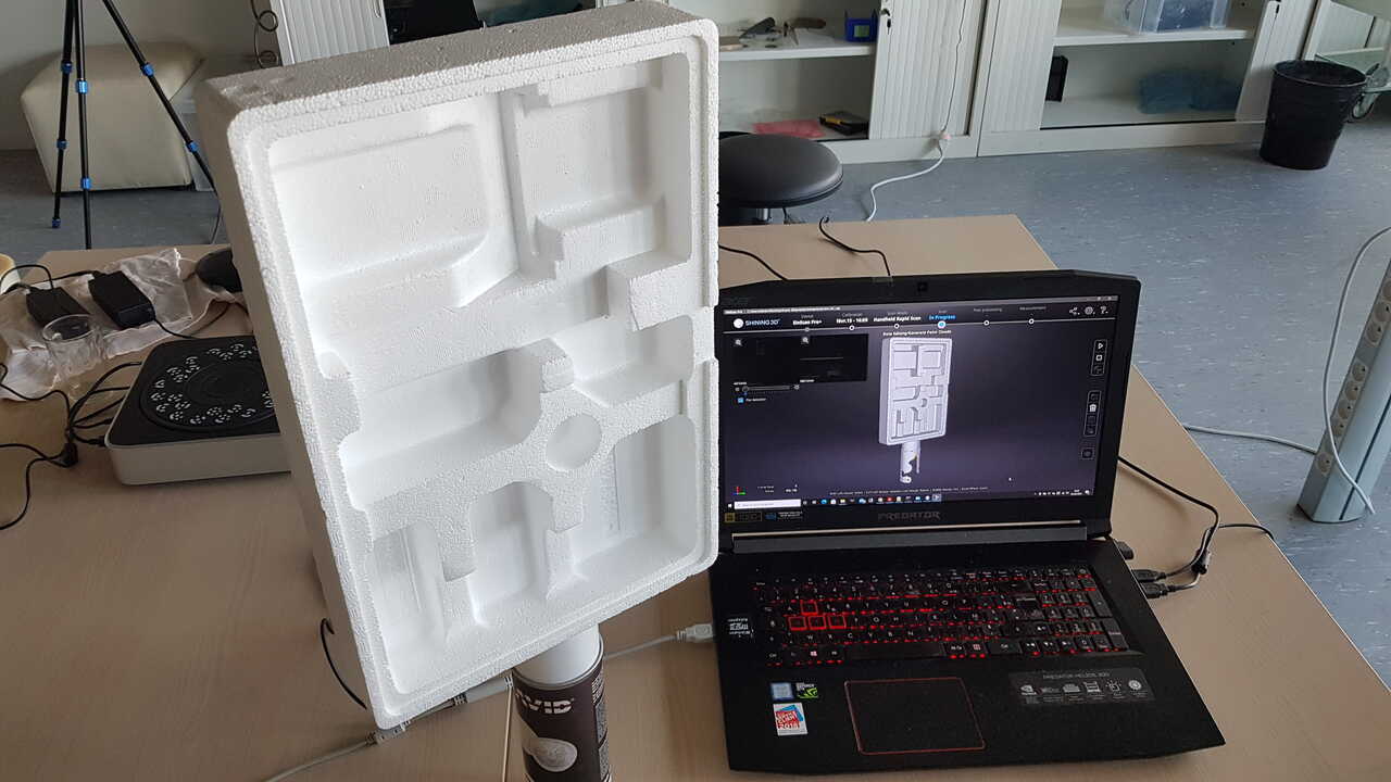 |
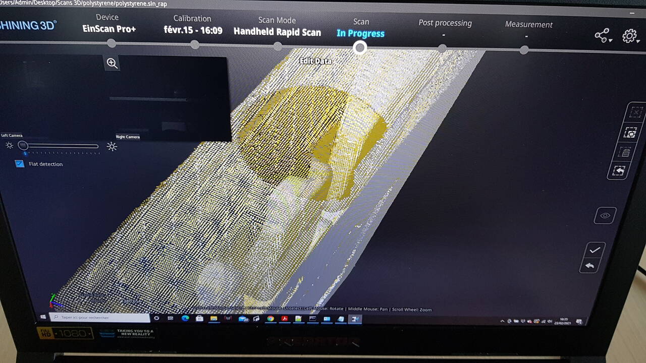 |
| Polystyrene box model and scan | Polystyrene box - points cloud (bottom view) |
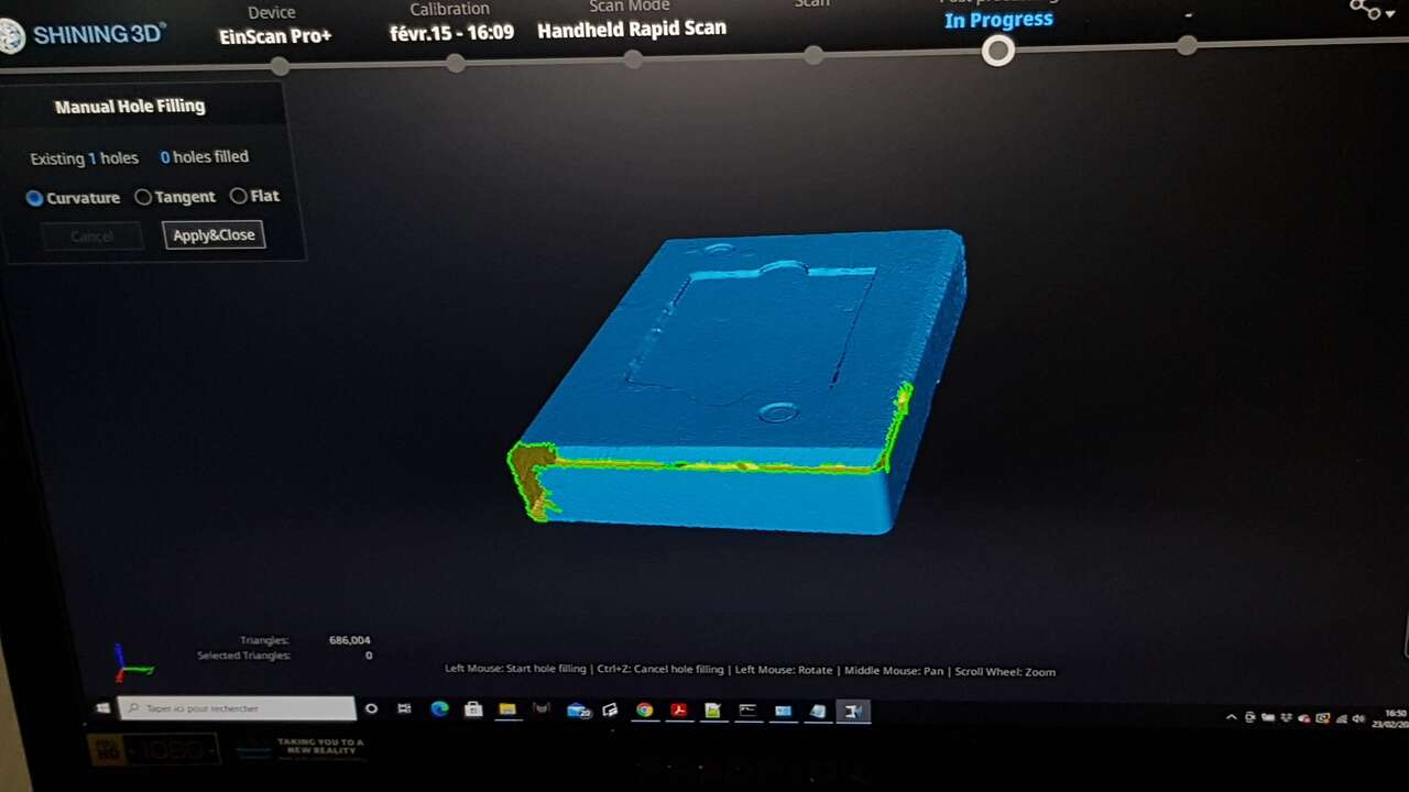
On the left side image below we can observe the presence of holes in the model (which is something very frequent), and on the right side image a demonstration of how those holes can be filled in the EinScan software.
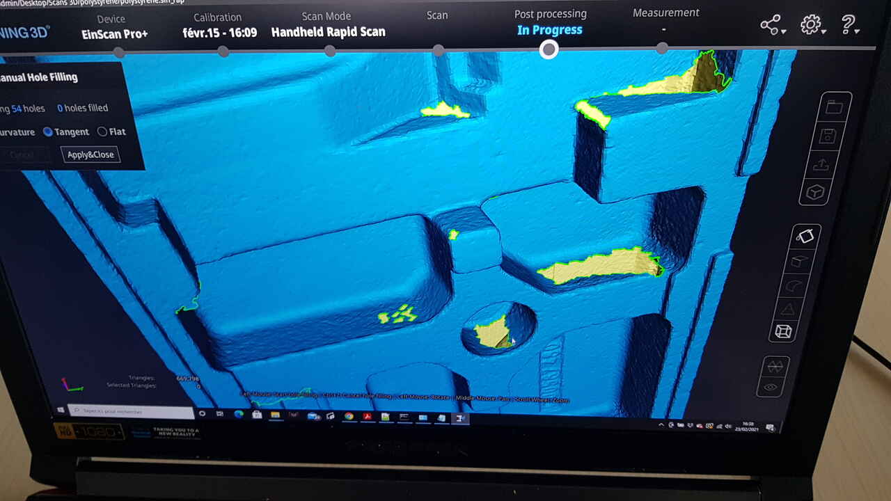 |
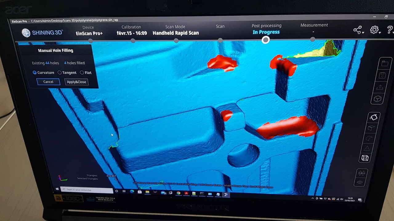 |
| Polystyrene box 3D scan with holes (yellow) | Polystyrene box - holes filling (red) |
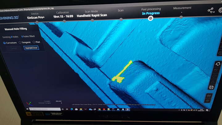
Also we can observe sometimes artefacts in the 3D model. They often appear when the points cloud is not cleant properly before generating the model. The images below present one artefact and how it could be corrected.
 |
 |
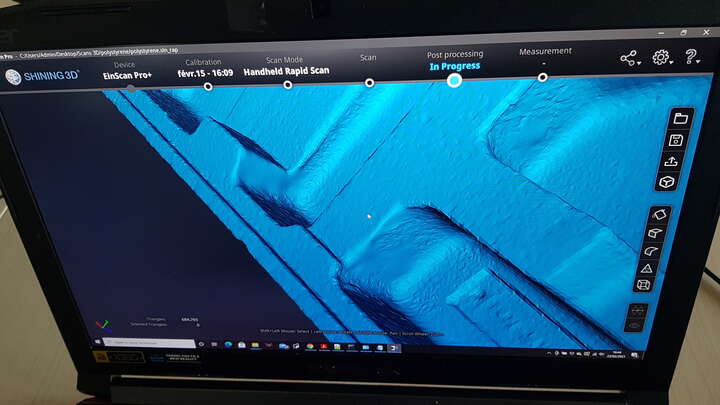 |
| Artefact | Artefact removed | Artefact hole filled |
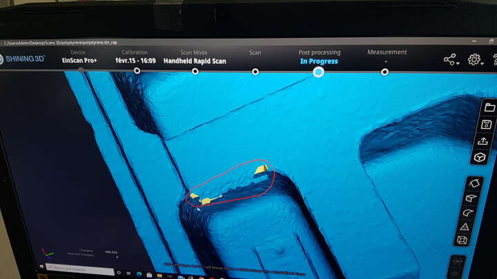
In the end we managed to fill all the holes in the model, except the one shown in the image hereunder which was too important to be filled in EinScan software. Indeed we could observe that there was a misalignment in one side of the box that lead to this important hole. If we would really have liked to use this 3D model we would have had to start again the whole scanning procedure on this box, but our intention was here just to get familiar with 3D scanning so we did stop here.
Polystyrene box model - limitation
Note : When scanning this polystyrene box, we noticed that it was quite difficult for the scanner to make the junction from the front side to the backside. We managed to perform this transition by using the spray bottle as a reference to help the 3D scanner to understand its position related to the object. If we would have liked better results, we could have had positioned intelligently a few stickers (as the ones presented in the “Additional material” section” on the backside of the box.
Scanning with 3D sense
As a 3D sense (2nd Gen) is available in the Fablab Digiscope, I wanted to give it a short try. As can be read on this article, 3D systems does not commercialize this product any longer and software support will also be stopped next year. As a consequence, I did not want to spend too much time focusing on this device.
Anyway, I decided to scan the same polystyrene box that I scanned with the EinScanPro+.
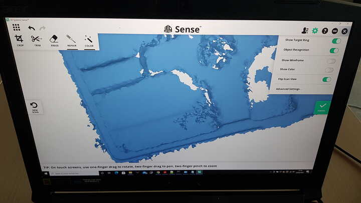
First comment is that it was way more difficult to scan the object with the 3D sense because the scanner got very often lost even though I was really paying attention to move slowly around the object while scanning. Also once the scanner lost track of its position, it was very painful to make it reconnect to previous parts of the object it had previously scanned. Thus, after a while of difficult scanning, I decided to stop and here is the result after basic cleaning of the points cloud obtained :
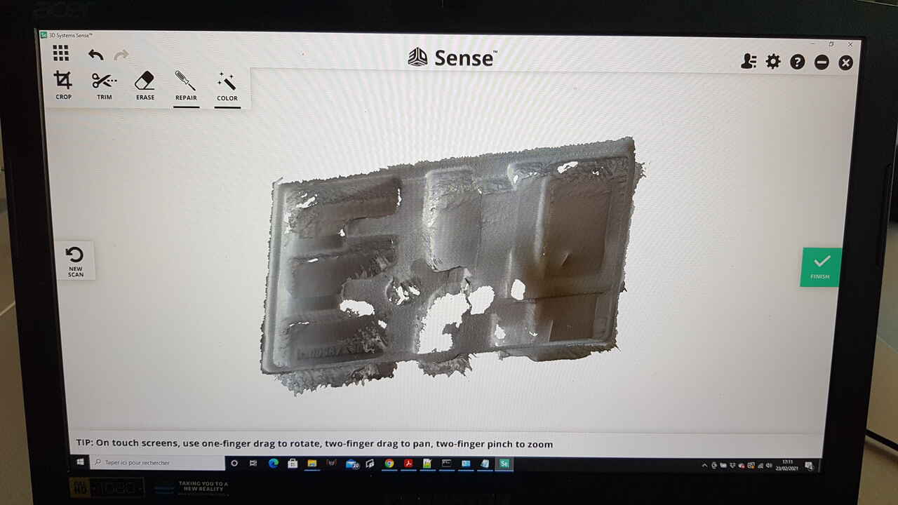
Polystyrene box - 3D sense scanner
The result is not that great and we can notice the presence of many holes.
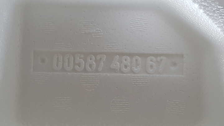
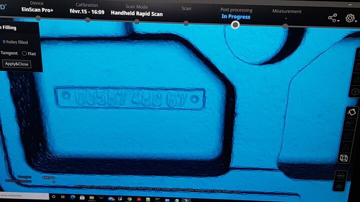
One thing this scan permitted to get aware of is that the texture feature is really misleading and can hide a poor scan quality. Indeed, in the beginning I thought that the scan quality was really good when looking at the results given on the series of digits embossed in the box.
 |
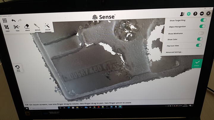 |
| Polystyrene box original - Numbers | Polystyrene box - 3D Sense scan WITH texture |
However, when disabling the texture feature in the software, we observe that the digits are simply not present at all in the scan performed with the 3D sense. In comparison, we can see that even though the quality was not perfect, those digits had been caught with the scan performed with the EinScanPro+ scanner (that does not present the texture feature).
 |
 |
| Polystyrene box - 3D Sense scan WITHOUT texture | Polystyrene box - EinScanPro+ |
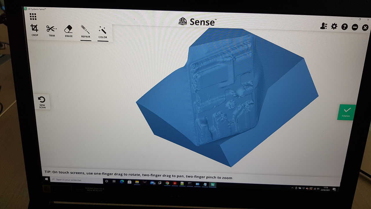
Even though the scan was of pretty poor quality, by curiosity I decided to give it a try to generate automatically the watertight model. This gave a weird result, but the trim command permitted to easily eliminate the strange outside shapes as revealed in the pictures below :
 |
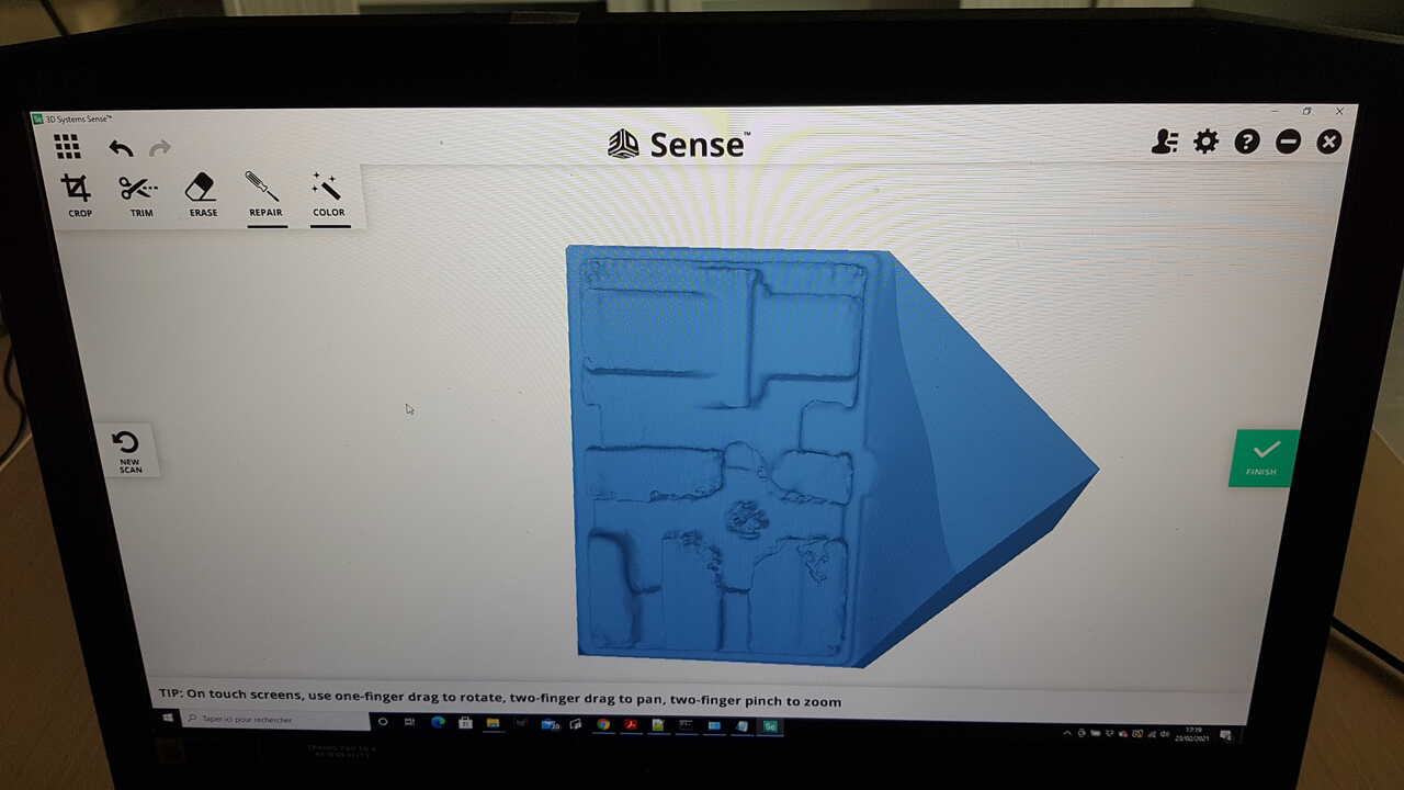 |
| Polystyrene box - 3D Sense watertight model | Demonstration of trim control |
In conclusion, it appeared that the EinScanPro+ scanner gave better results than the 3D Sense, but it was interesting to test and compare roughly those two 3D scanner and getting familiar with their respective post-processing softwares.
Additional material related to 3D scanning
Even though I did not have the opportunity nor the need to use such materials, I want to introduce here few objects that can be very useful for 3D scanning.
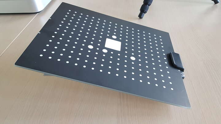 |
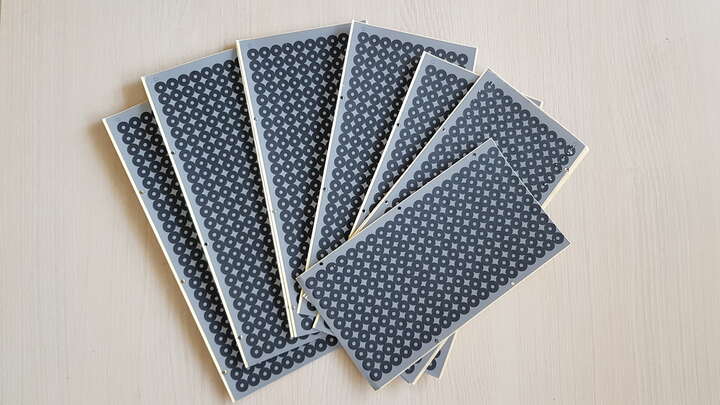 |
 |
| 3D scanner calibration matrix | 3D scan stickers | Coating spray |
- calibration matrix : when using a 3D scanner for the first time, and later on from time to time it is recommended to calibrate it for obtaining better results.
- scan stickers : when scanning objects which are symmetrical or present symmetrical faces, it can be very helpful to use stickers so that the scanner manages to always determine which part of the object it is scanning.
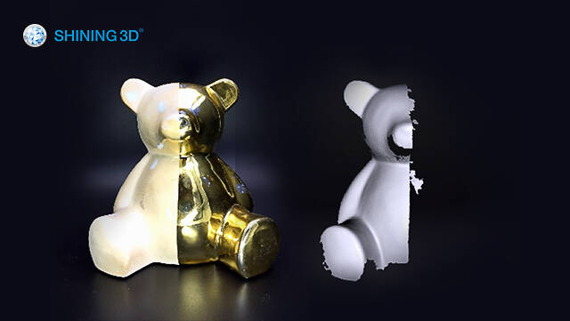
- coating spray : scanning shiny objects is very difficult or even impossible without using a special coating spray. The purpose of the spray is to cover the object with a matte white powder to make it scannable.
3D printing
3D Printing is a process for making a physical object from a three-dimensional digital model, by adding material layer by layer. This explains why this process is also called additive manufacturing. It is widely used for rapid prototyping and also in the industry and allows for creating objects and shapes that are not possible to create using subtractive manufacturing (by material removal). 3D printing can be performed using a wide variety of materials (plastics, metals, ceramics, biomaterials, etc) and includes a wide range of different technologies. The most common ones are FDM (Fused Deposition Modelling), stereolithography, DLP (Digital Light Processing) and inkjet. For further information on 3D printing, I recommend to read this article.
As for now, I will focus on FDM 3D printing technology which is one of the most popular technology and also the one I have had the chance to work with during this week.
FDM 3D printing
Before showing the possibilities those machines offer, the image below introduces the main elements that compose FDM 3D printers :
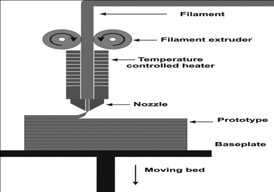
FDM 3D printer - overview
3D printers
The FDM printers available at Fablab Digiscope are Ultimaker S5 as well as older versions Uktimaker 3 and Ultimaker 2.
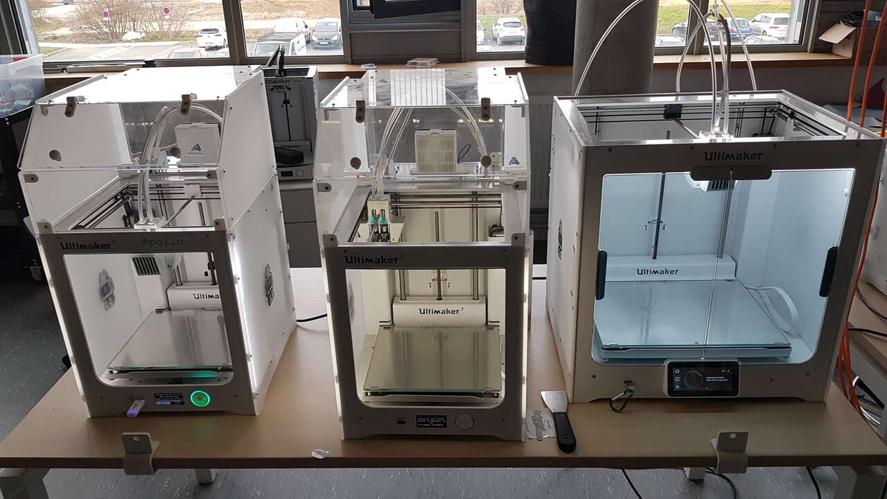 |
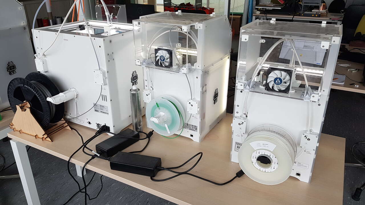 |
| 3D printers - Ultimaker 3 and Ultimaker S5 | 3D printers - backside |
Print core cleaning
Before starting our 3D printing activities my colleague Selena and I thought that it was interesting to learn how to clean the print core, which we did on the Ultimaker 3 printer following this very clear tutorial. Basically a complete cleaning process consists of 2 main phases that can be repeated as many times as necessary :
- Hot pull
- Cold pull
The idea is to use a PLA or cleaning filament, to insert it into the print head and to apply pressure on it so that material gets extruded, and then to pull back the filament either while the print core is hot or cold.
In the print core we cleant, a green PLA filament was fitted before. We cleant the print core with a white PLA filament. The image on the right hand side below shows the filament tips extracted step after step sorted by chronological order from left to right. Where green color can be seen on the tips it corresponds to hot pull, where brownish color appears it corresponds to cold pull.
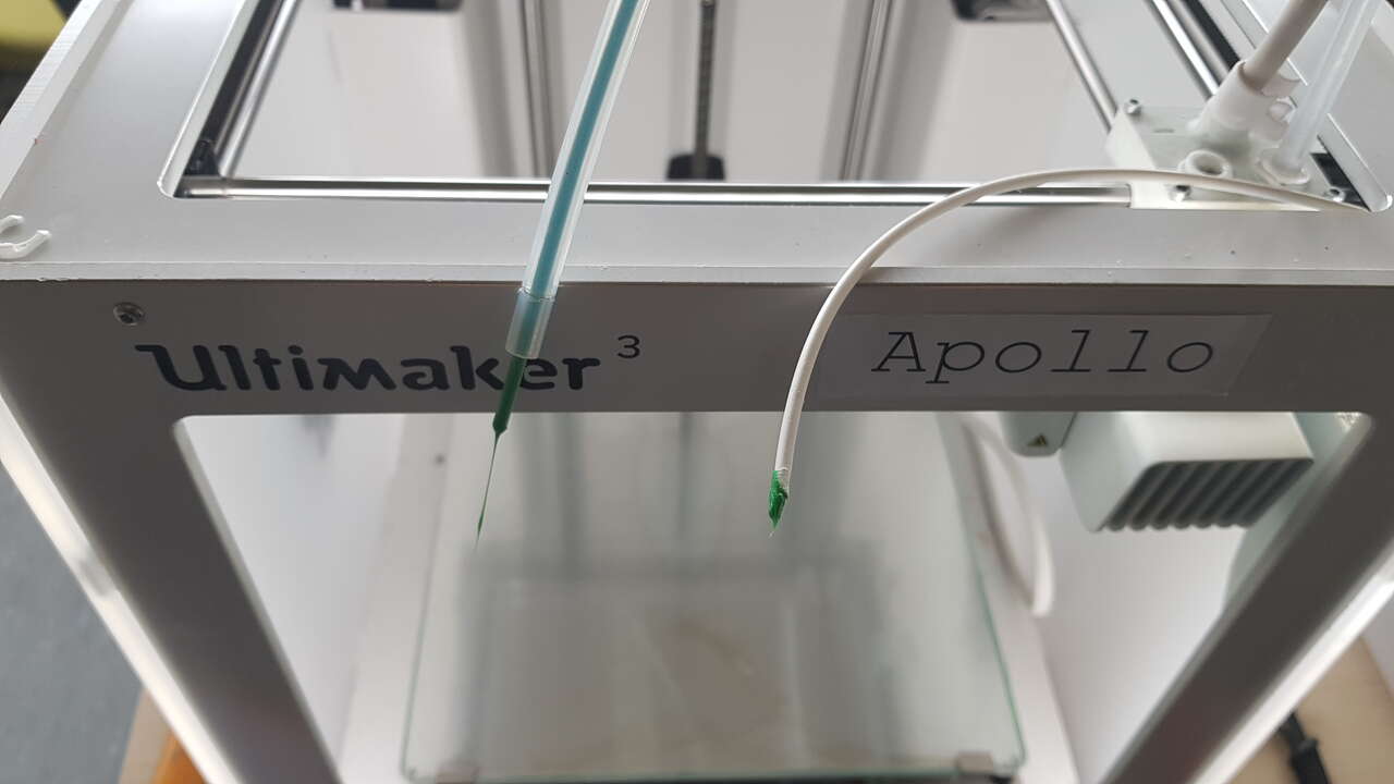 |
 |
| Printhead cleaning with PLA filament | Cleaning filament tips step after step |
Build plate calibration
Once the cleaning performed, we decided to address the build plate calibration which is a crucial activity in the sense that it dictates how well the nozzle will be able to release material and apply pressure on it during the printing.
- Too high plate : nozzle will not be able to release the print material quantity expected.
- Too low plate : nozzle will not apply sufficient pressure on the material to make it fit properly on the plate and then on the successive material layers.
- Non-flat plate : the 3D model will not be printed as regularly as expected, and final result will definitely be impacted.
To conduct the build plate calibration on both 3D printers models available at Fablad Digiscope, we carefully followed the instructions given in Ultimaker 3 tutorial and in Ultimaker S5 tutorial.
The calibration only requires a few minutes and basically consists of the following main steps :
1 - Level up the build plate.
2 - Tighten evenly (roughly) the 3 screws located below the build plate.
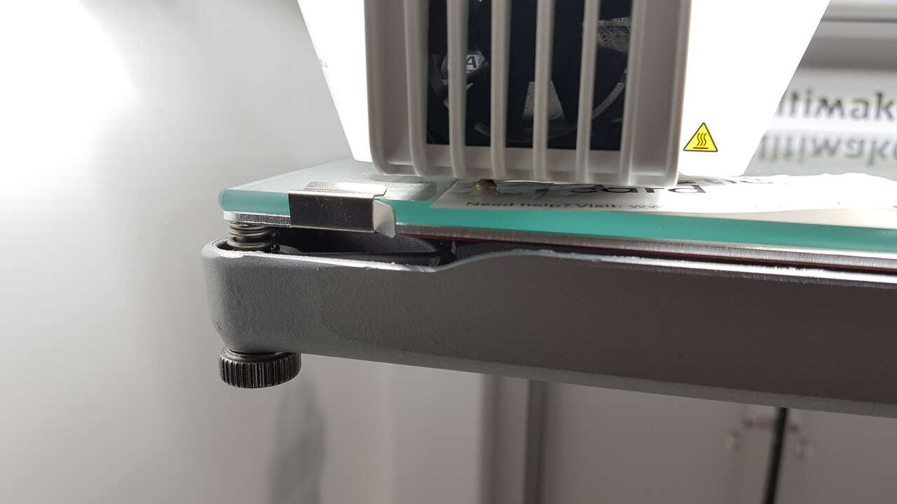
3 - At the beginning the print head is located at the rear center and the machine. Adjust the build plate level using the machine interface so that it is exactly 1mm away from the nozzle. In order to do so, use a 1mm wedge as shown in the pictures below. Then the print head moves successively towards the front right and front left corner of the machine, adjust the build plate using the dedicated screws so that the nozzle is also 1mm away from the plate at each front corner.
 |
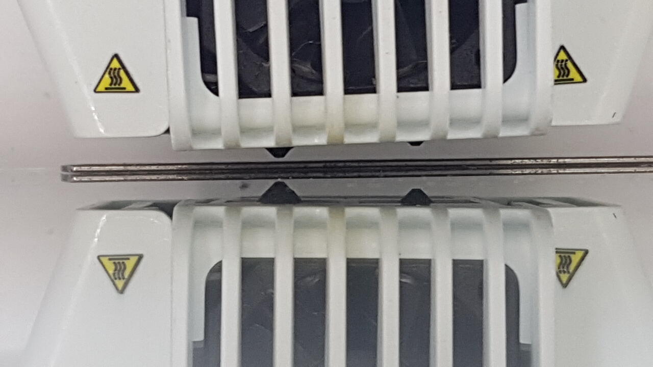 |
| Build plate calibration 1mm | Build plate calibration 1mm - zoomed in |
4 - Then the nozzle will successively move again from the rear center towards the front right and front left corners where a fine tuning (using a calibration card, or a simple piece of paper) must be performed using the dedicated screws. Once this step is finished, the build plate is thus extremely close to the nozzle.
Build plate fine tuning
5 - Then on Ultimaker 3 and Ultimaker S5 which both have 2 print cores, the print core 1 nozzle will get raised, while the print core 2 nozzle will get lowered. The idea is to finalize the calibration by adjusting the build plate level with the second print core nozzle.
Warning: This last step must absolutely be performed with the 3D printer interface as indicated on the machine display, NOT with the rear center screw. This will level up the whole plate, not only the rear part. By mistake I did this final step using the rear screw and as a consequence it made my build plate not flat and resulted in the failed first print that is presented on the left image below. We can clearly see on this picture that the material was not dropped properly at the rear of the object because the plate was too hight there, preventing the nozzle from extruding material in this part of the object.
After I noticed this issue, I recalibrated my build plate correctly, and the result was perfect as shown on the right image herunder.
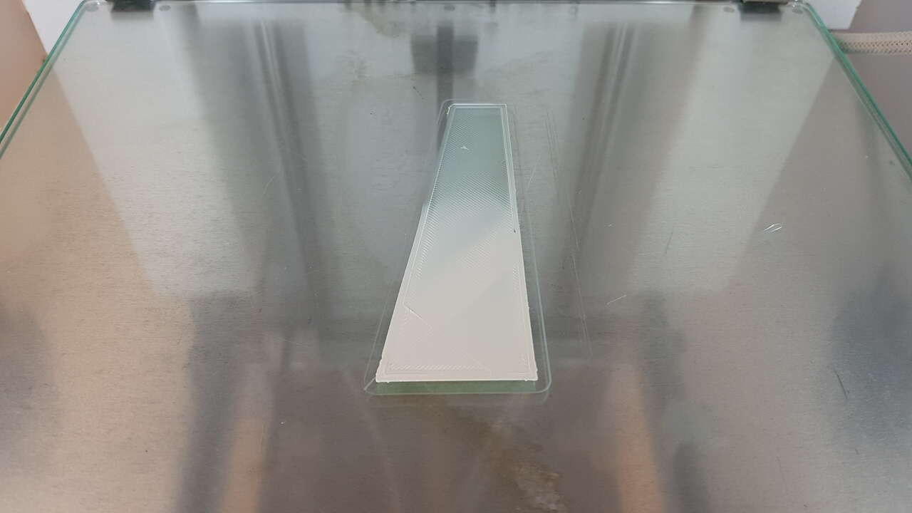 |
 |
| First layers printing - calibration issue | First layer printing - correct calibration |
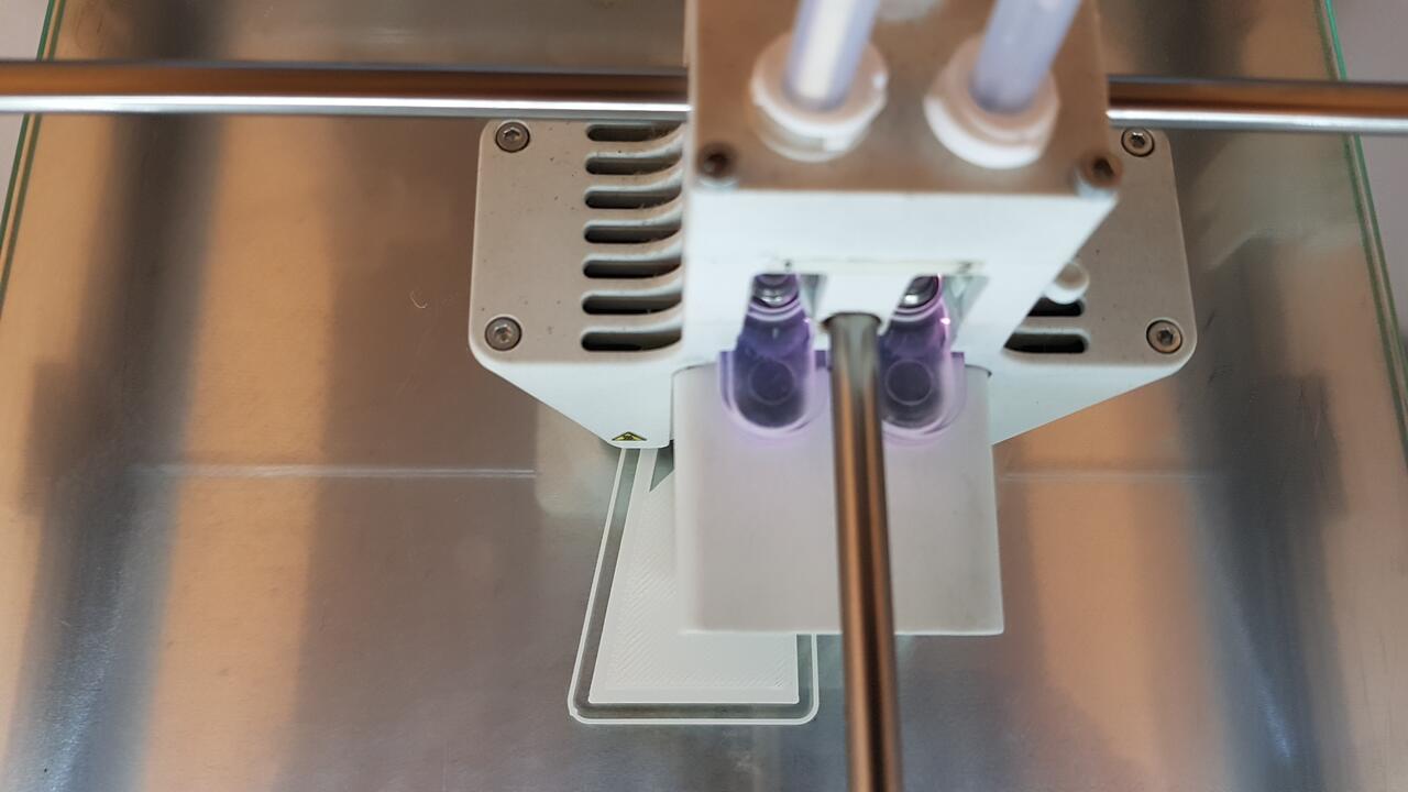
Short video demonstrating that the first layer of material is perfectly applied on the build plate when the calibration of the build plate has been done thoroughly. It is a good example that there is no need to use spray glue with a correct calibration.
Slicer software
In the world of 3D printing, slicers are programs that convert digital 3D models into printing instructions for 3D printers. Ultimaker’s Cura is an open souce, powerful and easy to use slicer which makes it one of the most popular slicers. Not only can it be used with Ultimaker 3D printers but it is also available for prepararing files for 3D printers of many other brands.
Here are the main basic steps for using the software :
- Select the 3D printer model. This especially updates the work platform size accordingly.
- Import the 3D model(s) to be printed.
- Adjust the model(s) size and positionning on the build plate.
- Select the material type (PLA, PVA, etc) and the printcore nozzle size (0.4mm, 0.8mm, etc).
- Set the parameters desired. Note: there are hundreds of them but to give a few examples one can set the infill density, the layer height, the wall thickness, the printing temperature, the presence of supports and their specific parameters, etc. I will not give an exhaustive list here but those parameters are very important and will have a strong influence on the print time and quality.
- Slice the object, and make sure that the print sequence proposed is fine.
- Check the print time indicated and the material consumption, and copy the prepared .m3f file into a USB stick.
- Connect the USB stick to the 3D printer, and start the print job.
- And wait....
Indeed one important fact to emphasize, is that 3D printing takes a lot of time.
Below are presented some screenshots of Cura preparation work with some available settings. What is interesting in the picture below is to notice that the parts of the objects that would require supports for printing are identified in red color.
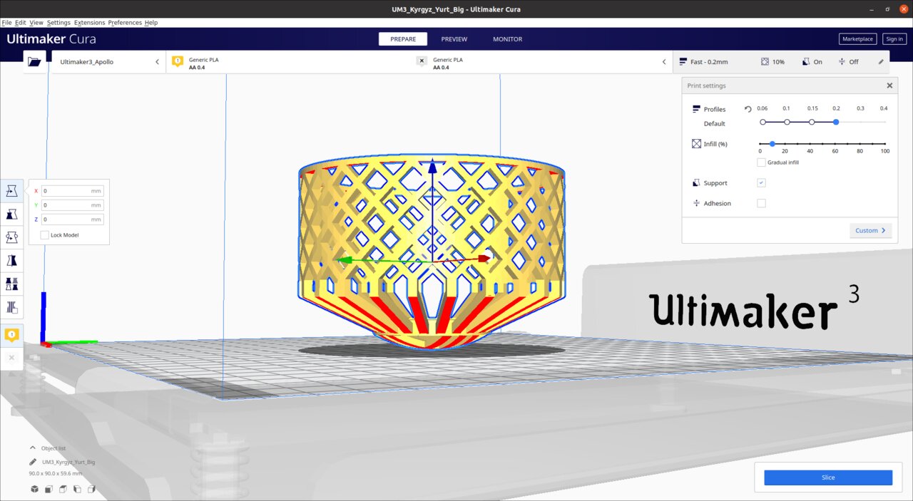
Cura yurt model preparation
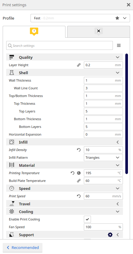
Cura settings - brief extract
And to conclude this section, a short video demonstrating the result of the slice action.
Characterization
In order to characterize the Ultimaker 3 printer, I have 3D printed several models designed on purpose and available as “.stl” files on the FabAcademy 3D printing week page. The whole idea of those tests is to assess what performance the machine is able to achieve in terms of angles, bridges, walls, domes, etc. without using supports. Such tests also exist for characterizing supports but I did not spend much time on those. In this section, I present all the results I obtained using the following main parameters :
- material: Colorfab white PLA
- nozzle: AA 0.4mm
- layer height: 0.1mm
- wall thickness: 1.5mm
- infill density: 10%
- speed: 70mm/s
- printcore temperature: 200°C
- build plate temperature: 60°C
Full assembly
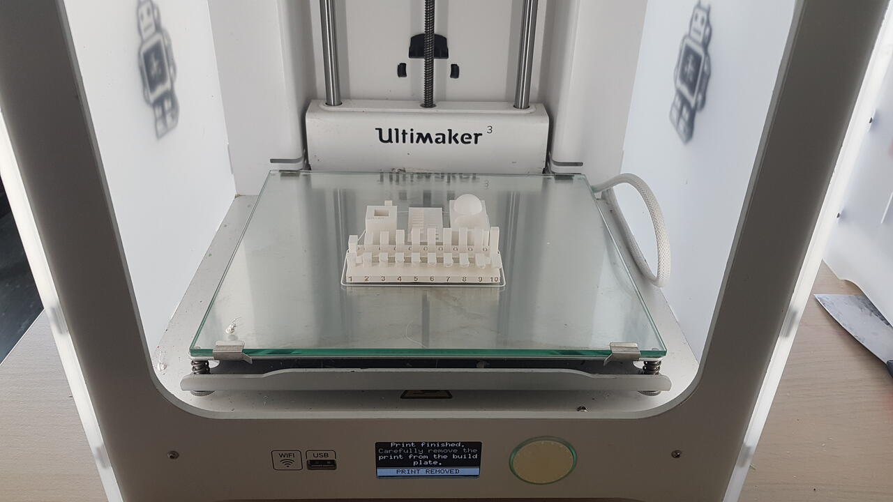 |
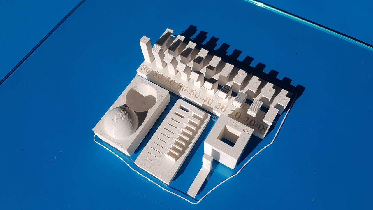 |
| Ultimaker3 - characterization assembly in 3D printer | Ultimaker3 - characterization assembly |
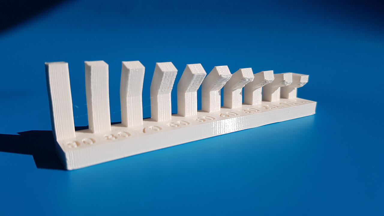
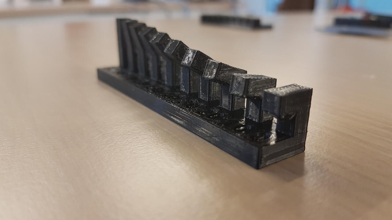
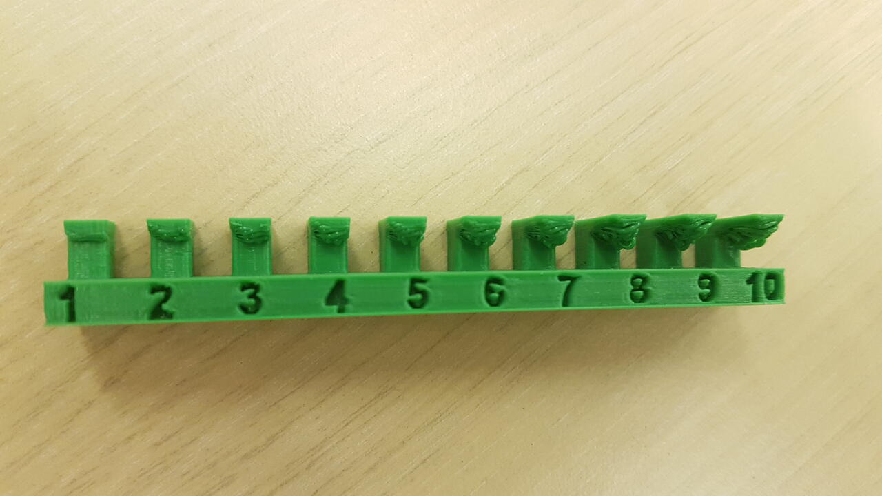
Angles test
 |
 |
| Ultimaker3 - angles test full view | Ultimaker3 - angles test zoom in |
- [0°-20°] : the 3D printer can make it but results are not clean at all
- [20°-40°] : results of medium quality
- [40°-90°] : good results
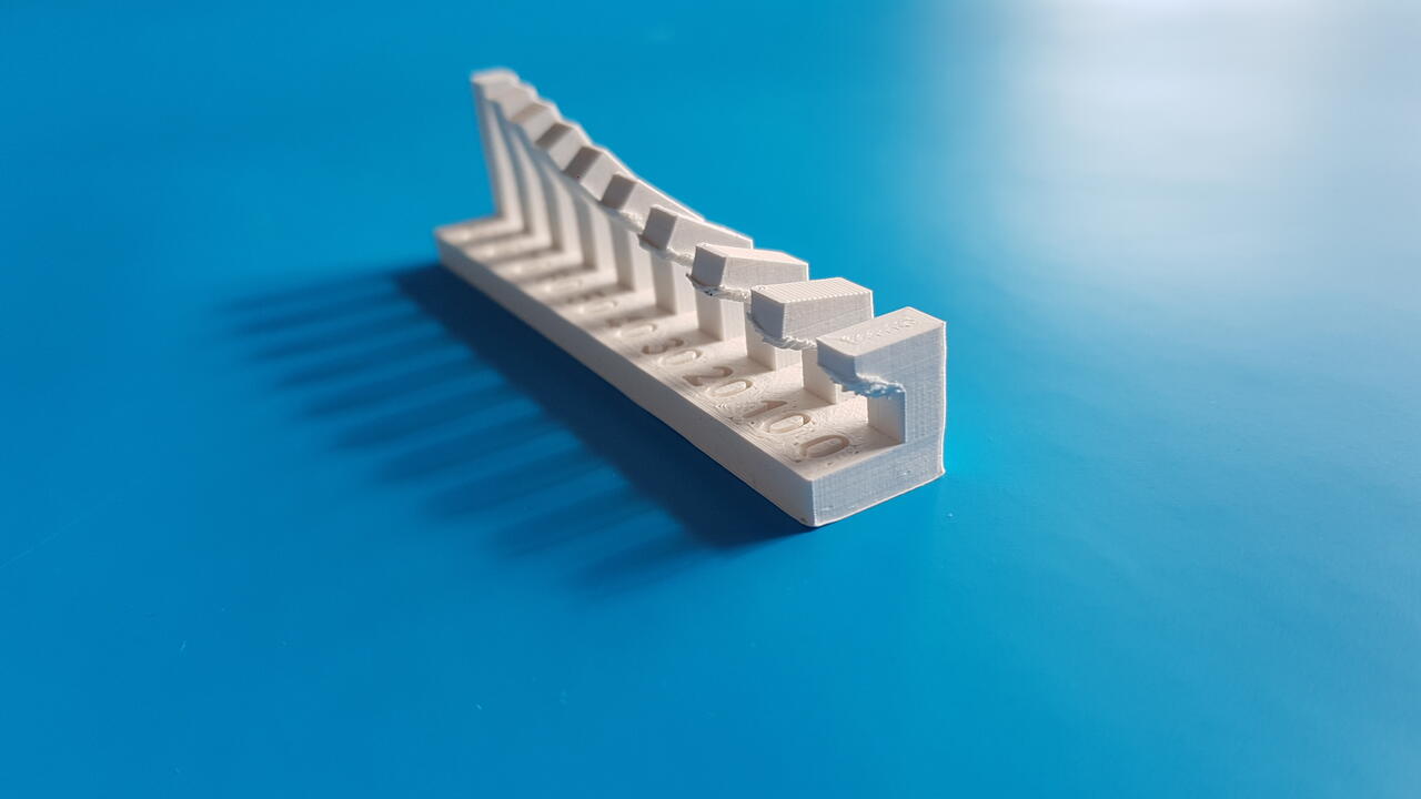
Overhangs
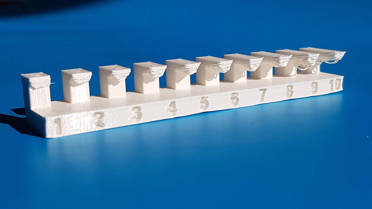
Ultimaker3 - overhangs test
All results are of pretty poor quality. I feel that the printhead temperature was maybe a little too high.
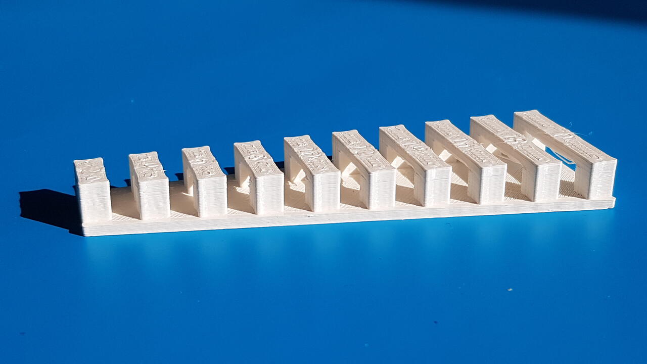
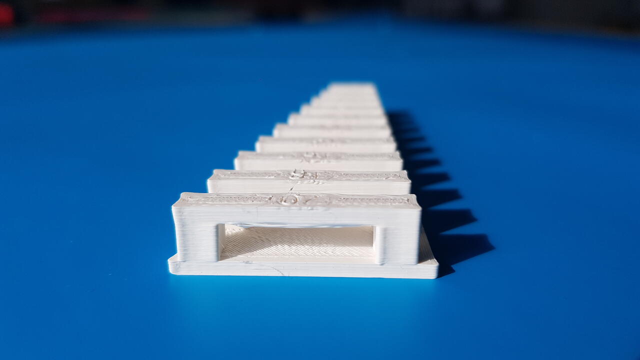
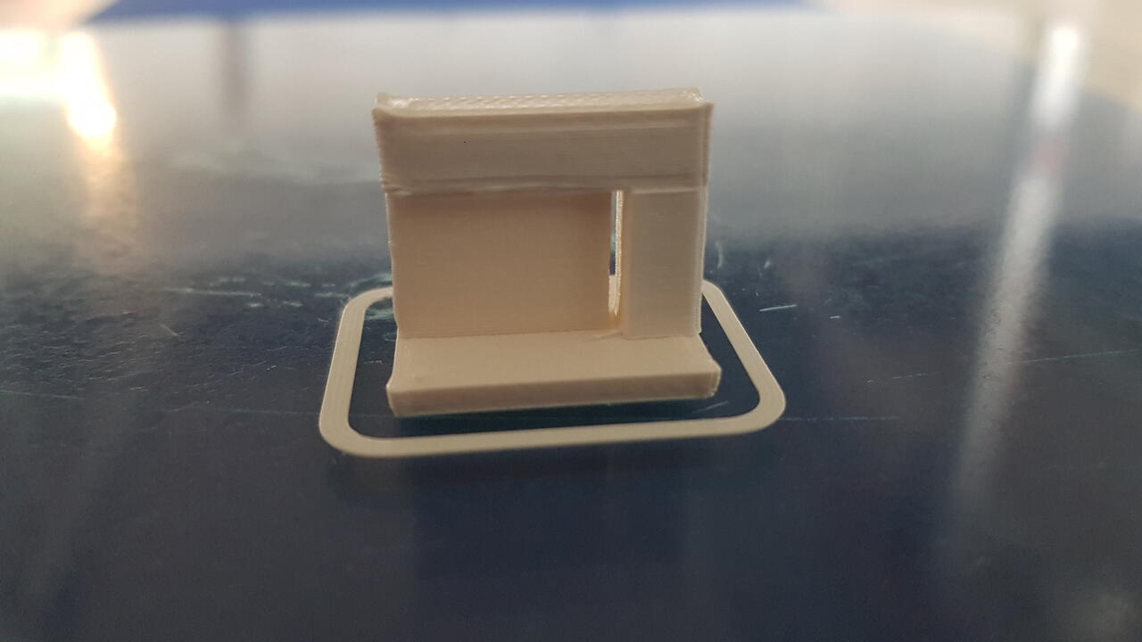
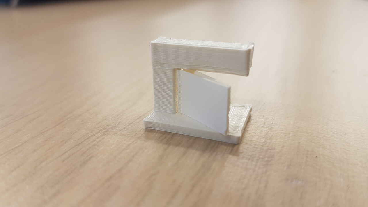
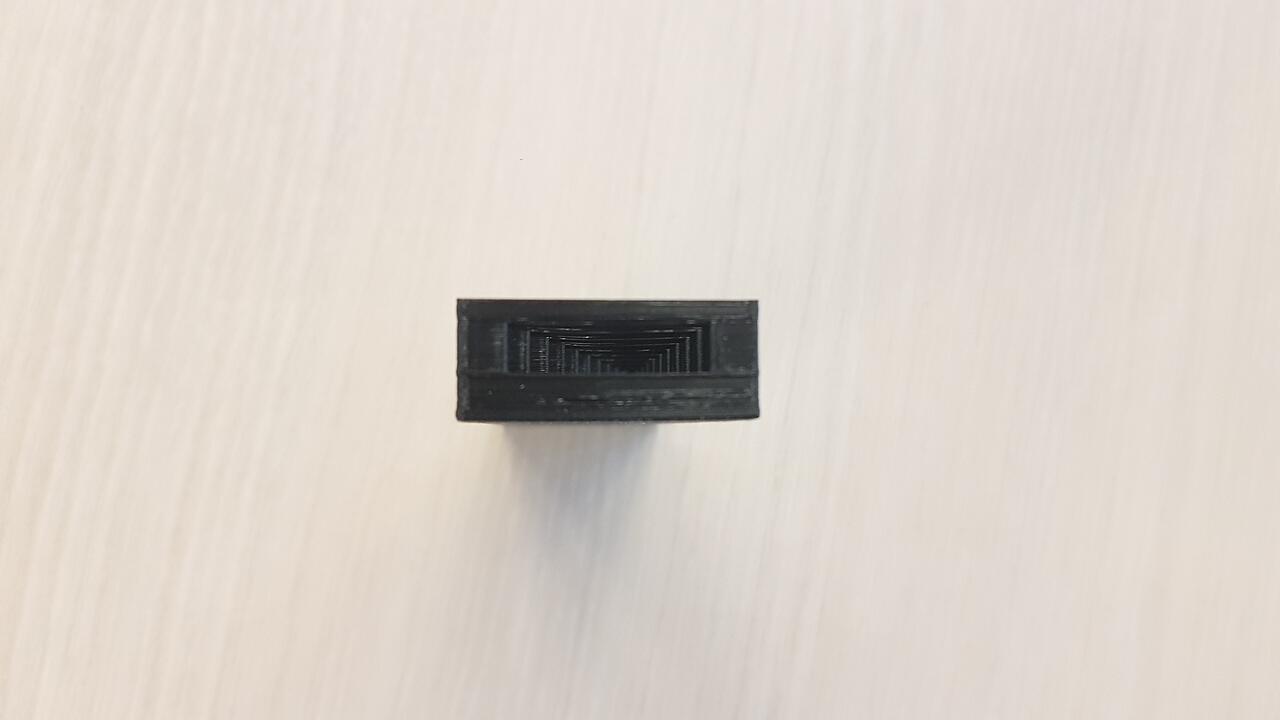
Walls and slots
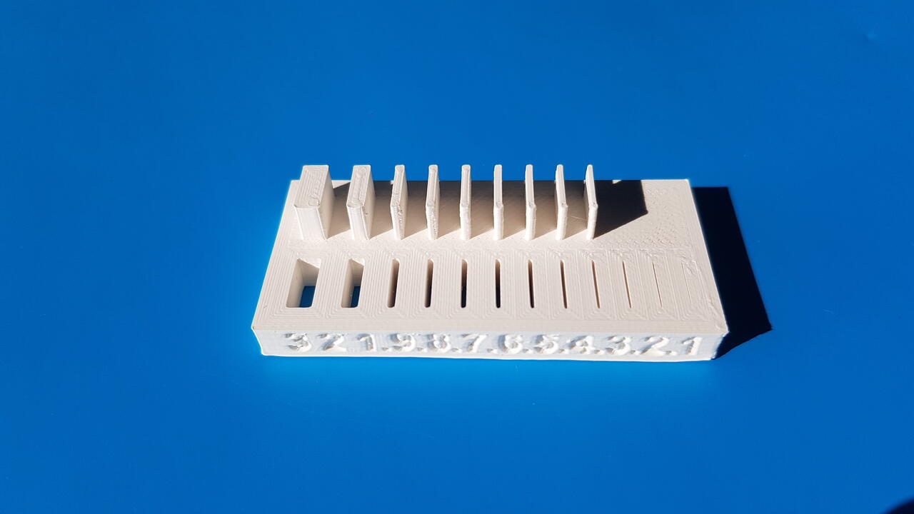
Ultimaker3 - walls and slots test
Walls can be built until 0.4mm without any problem, and slots until 0.3mm.
Bridges
Note: This bridge test has been printed in another job, with the same machine but with an infill density of 20%.
 |
 |
| Ultimaker3 - bridges test | Ultimaker3 - bridges test zoom in |
The printer managed to print all bridges up to 20mm, but once again the results are not very clean when looking under the bridges.
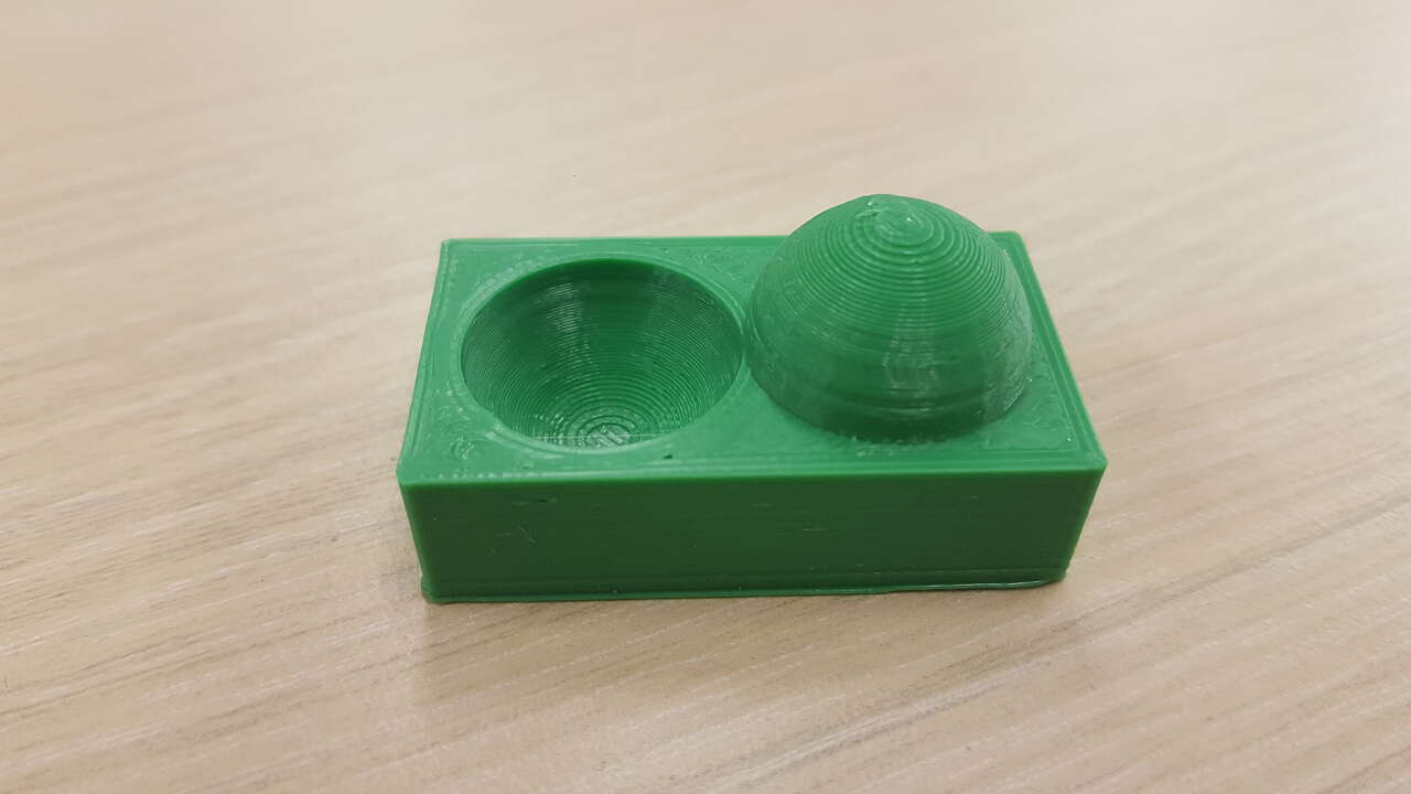
Dome and crater
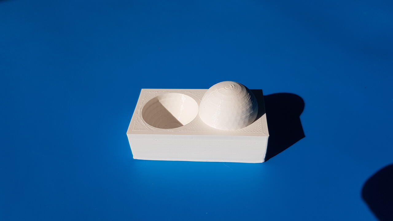
Ultimaker3 - dome and crater test
Really nice accuracy.
Cube
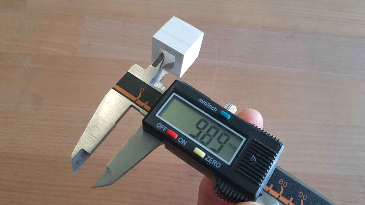 |
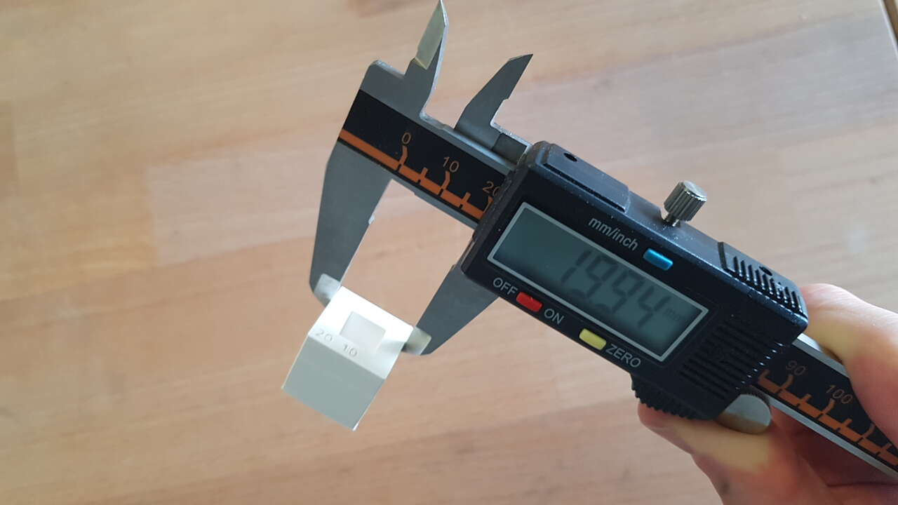 |
| Ultimaker3 - cube test - internal measure | Ultimaker3 - cube test - external measure |
After measurement I observed 0.06mm difference compare to the design in the outer part of the cube, and 0.11mm in the internal hole.
However, I also noticed a deformation at the cube’s base. Was the build plate temperature too hight ?
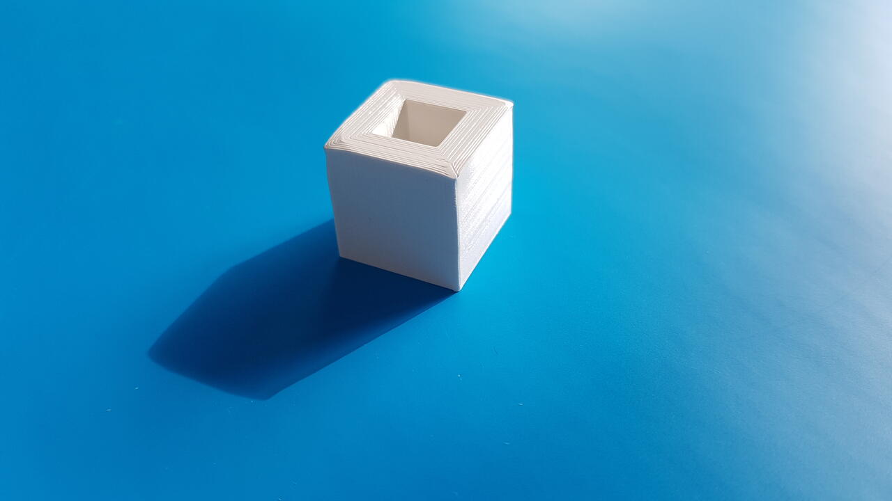
Ultimaker3 - cube base deformation
Supports :
Below is presented a quick example of how supports work. Those pieces can be easily removed after print (when the correct parameters have been chosen in the slicer), and permit to obtain a better print quality for overhangs, bridges, angles, etc, but also to 3D print models which could not be achievable without them.
 |
 |
| Ultimaker3 - support test | Ultimaker3 - support partially removed |
Comparison with another printer :
Similar characterization tests have been performed by my colleague Selena Pere with other 3D printers. Results are presented below :
 |
 |
| Creality Ender 3 - bridges test (0.4mm nozzle) | Creality Ender 3 - angles test (0.4mm nozzle) |
 |
 |
| Ultimaker S5 - dome (0.8mm nozzle) | Ultimaker S5 - overhangs (0.8mm nozzle) |
When looking at the bridges and angle tests performed with the Creality Ender 3, we can notice that results are way cleaner that what we obtained with the Ultimaker 3 for similar printing parameters. Investigations are ongoing to try to understand the poor quality obtained with Ultimaker 3.
As for the Ultimaker S5 (0.8mm nozzle) we can observe that results for the overhangs test is even worse than with the Ultimaker 3 (0.4mm nozzle).
And finally, a quick video to show the test assembly printing ongoing on the Ultimaker S5 printer.
Yurt model printing
As already presented in my CAD week page, I have worked on a Kyrgyz yurt model in OpenSCAD software. This week I have managed to complete the model and to make it fully parametrical, which allows me in a few seconds only to have a totally different yurt appearance.
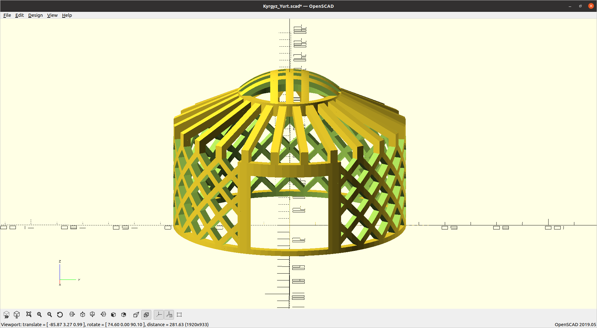 |
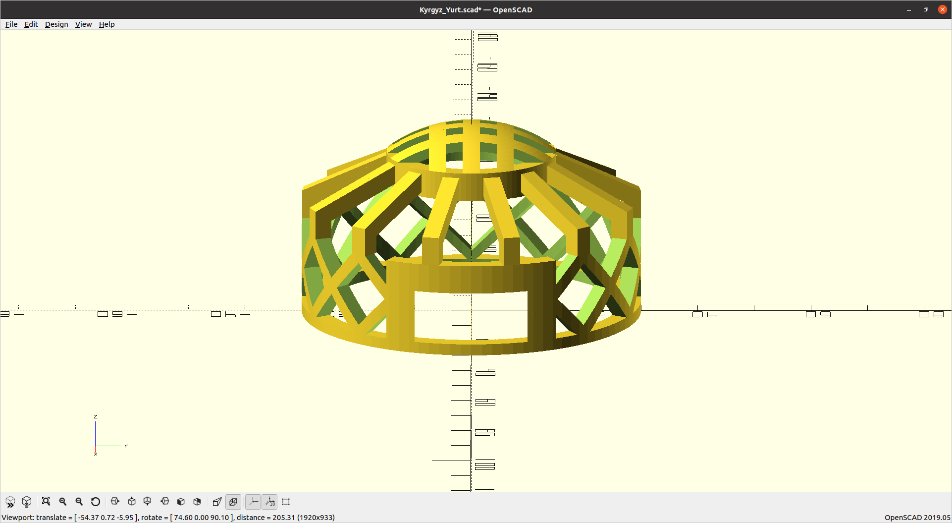 |
| Large yurt model - OpenSCAD | Small yurt model - OpenSCAD |
Source file is available for download here : Kyrgyz yurt - OpenSCAD model
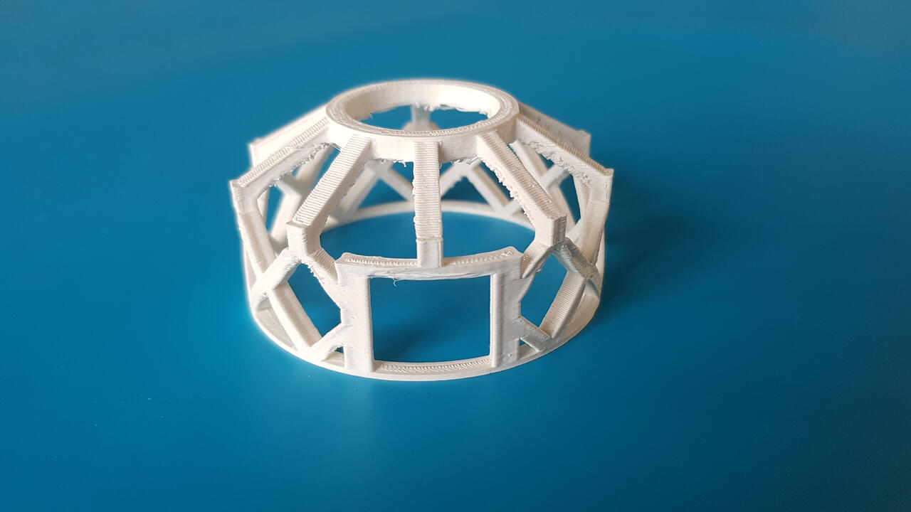
This parametric design permitted me to print first as a test a small and “simple” version of my model (without the top part that I had not finished to design yet). As I did not have the time to experience much with Cura slicer at that time, I basically started the print with the default parameters and without any support to see what the result would be. As expected some issue occur on the top part which would have had requested supports, but I was quite satisfied with the result as it was the first time I 3D printed a model that I designed.
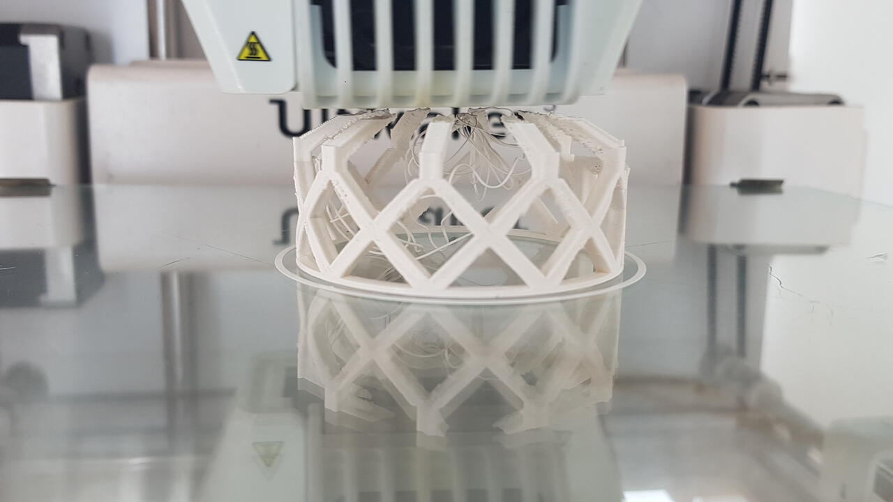 |
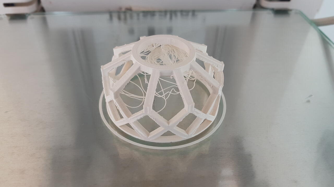 |
| Ultimaker3 - yurt top partial failure | Ultimaker3 - yurt final result |
 |
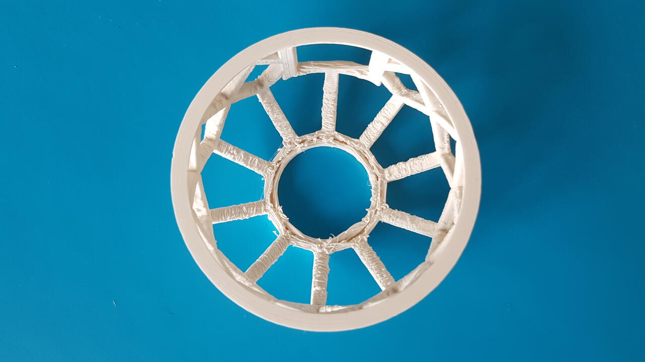 |
| Ultimaker3 - yurt final result after cleaning | Ultimaker3 - yurt inside view |
Following this, I have adjusted my model so that it offers both options : one option with support and another one without supports. What changes between those 2 options is the positionning of the diagonal posts related to the top cylinder frame.
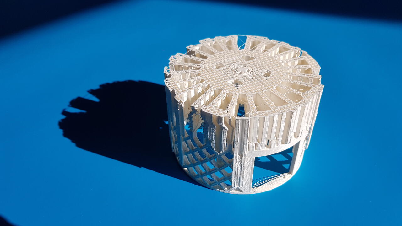
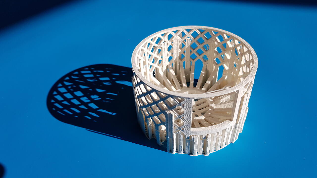
However, I was not very happy with the print quality in the angular parts, so I decided to print this time a larger yurt that I positionned upside down using supports. The results are presented in the images below :
 |
 |
| yurt model with supports - flipped | yurt model with supports - print orientation |
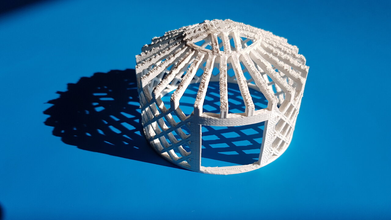 |
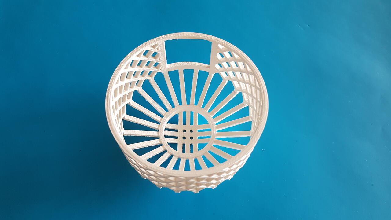 |
| yurt model - outside view | yurt model - inside view |
Although supports have been used this time for the print, I am still not happy with the result quality. My colleague Ambroise De Vries kindly printed for me a small version of the yurt with his Creality 3D printer, and we can see that the result is way better, although using the same printing parameters :
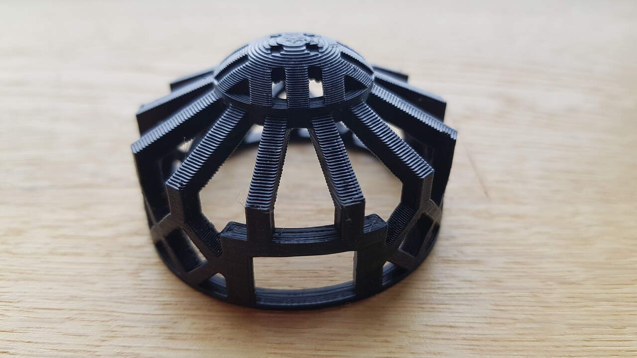 |
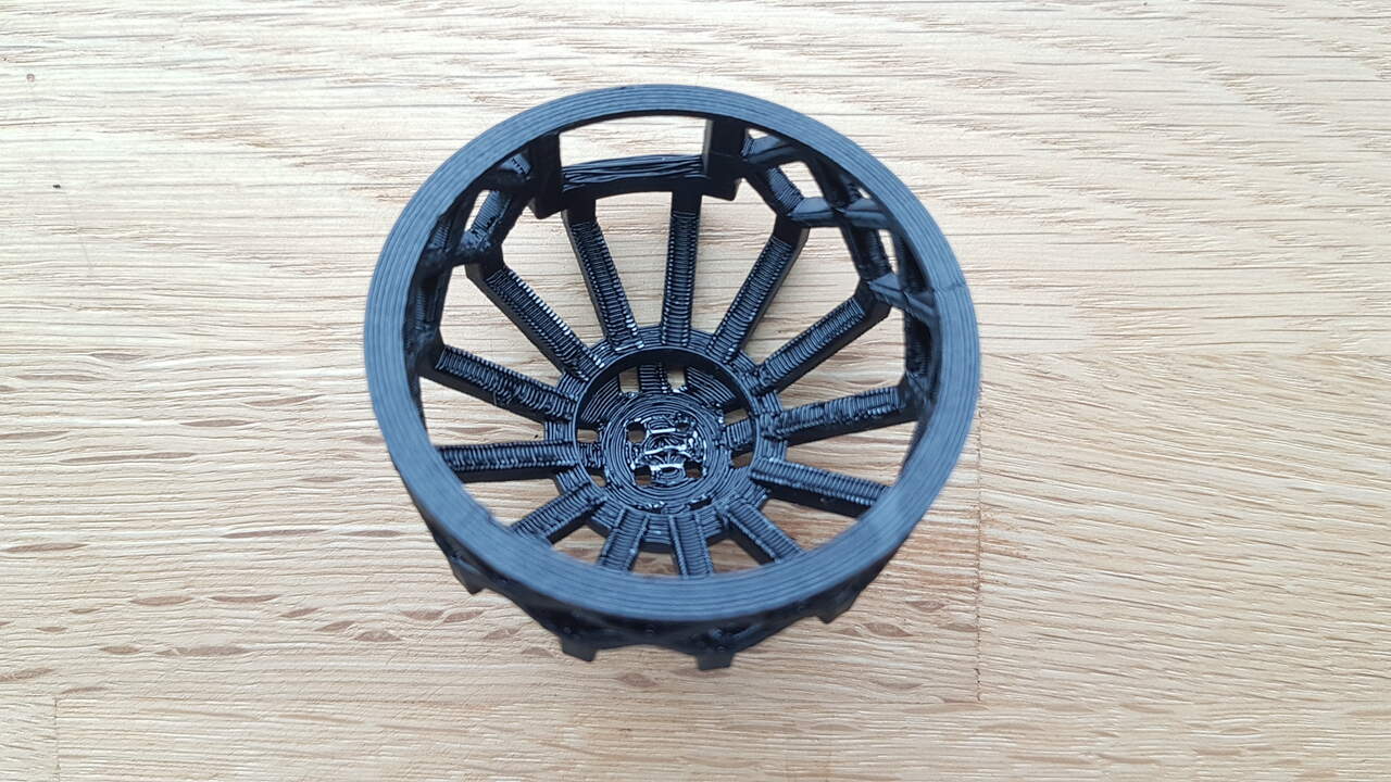 |
| yurt outside - Creality printer | yurt inside - Creality printer |
And to conclude this chapter a quick video of the 3D print in progress for my first yurt model.
Source file
The source file of the work presented in this week assignment is available for download here :