12. Output devices
Assignments:
Individual assignment:
- Add an output device to a microcontroller board you’ve designed, and program it to do something.
Group assignment:
- Measure the power consumption of an output device.
Solenoid lock mechanism
The first output device I have worked with during this Fab Academy program is a 5V solenoid lock mechanism. I showed interest to this particular device as the puzzle box I design for my final project will implement at least 2 of those devices.
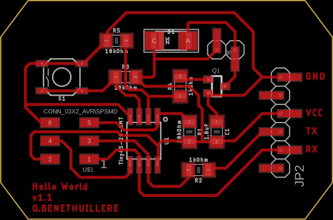
During the electronics design week, I customized an hello world board to allow controlling the solenoid opening/closing based on user action on a push button. Herebelow is presented the electronic design performed in Eagle, as well as the final PCB with all the components soldered.
 |
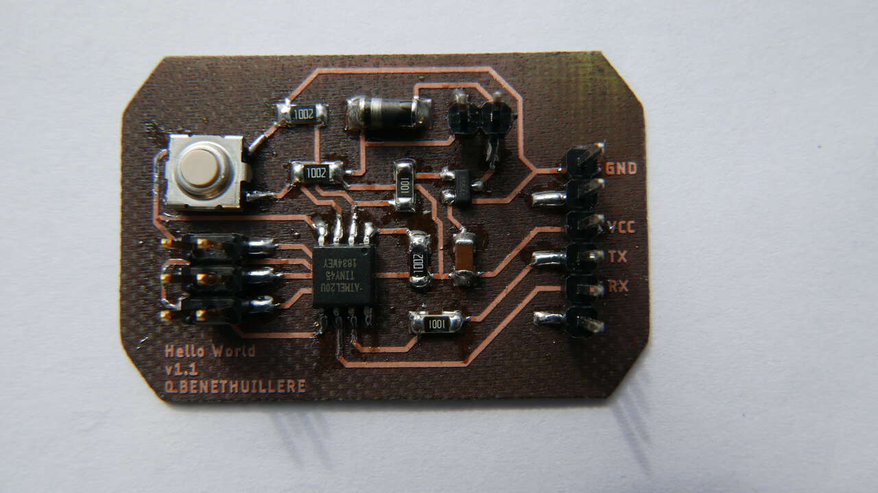 |
| Hello world + lock mechanism - board | Hello world + lock function - final PCB |
Among the main components added for the solenoid control, it is worth mentioning a MOSFET and a diode.
- The MOSFET allows to control the lock mechanism and is the one that permits to deliver enough current to the solenoid (about 700 mA) to maintain it open.
- The diode has a protection role, as it allows the current stored in the solenoid to flow when the power supply is turned OFF.
Later on, during the embedded programming week, I had the opportunity to test different software implementations to control this lock mechanism. Those are presented in the videos hereunder. Note: As opening the solenoid requires an important amount of current, it also generates heat and thus it is not recommended to keep it open for more than 15 seconds. Taken this into consideration, I implemented a protection solution that automatically closes the solenoid after a few seconds even though the user is still pressing the push button (2nd video below).
LCD and servomotor
Other output devices I want to integrate in my final project are a LCD (Liquid Crystal Display) and a servomotor. The LCD will be used as a feedback for players, both to give messages while progressing through the game, and also would be part of a puzzle that requires player to enter a particular sequence on a keypad.
I already had the opportunity to work on a first Arduino version of this program, using a LCD controlled via the 16 connection pins :
Then I ordered additional electronic module that allows i2c communication with the LCD, which is how I want to communicate with the LCD in my final project in order to reduce the number of connection pins required. Once this module received, it was an excellent opportunity to work on an improved version of the Arduino project presented above, that also integrates the custom DNA keypad I produced in the molding and casting week as well as a servomotor that will act as the lock mechanism in my puzzle box.
This tutorial (in french), was of a great help to understand how servomotors work and how to control them with the Arduino “Servo” library. As I had some issues with my servomotor sometimes spinning loose, I even had the chance to open it and physically observe what I had read in the tutorial about the DC motor, gears and the potentiometer.
At this level I did not spend time calibrating precisely the servomotor in terms of angular position as I do not know yet exactly how I will integrate it into my final design and whether I will use the small servomotor presented in the video (MG90D) or a slightly bigger one (MG995R) to get extra torque.
Note: More information (sketches, source code, etc) about those programming activities can be found in this section of my final project page.
7-segments digits countdown
As in almost every escape game, my puzzle box will integrate a countdown that indicates how much time the players have left before they fail the mission they have been assigned.
Arduino
Early in the FabAcademy program I developed my countdown program with Arduino :
Fritzing sketch of the electronic assembly :
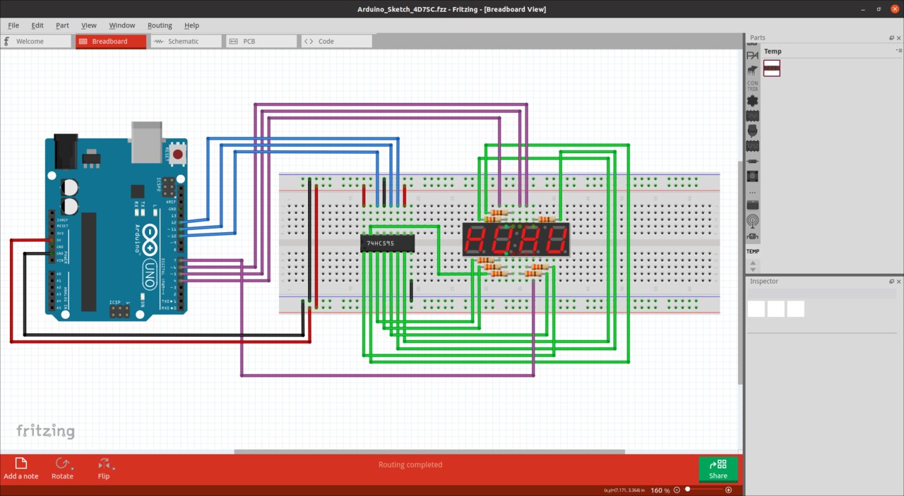
Countdown mechanism - Fritzing skecth
Material :
- Arduino Uno (x1)
- Breadboard (x1)
- 8 bits shift register (74HC595) (x1)
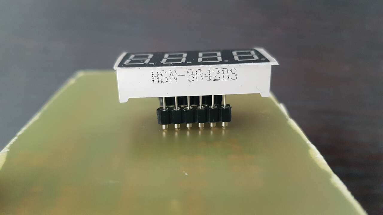
- 4 digits 7 segments display (HSN-3642BS) (x1)
- 330Ω resistors (x8)
It is worth noticing the use of a 8 bits shift register component which allows to reduce the number of digital I/O pins required. Without this component or a BCD (Binary Coded Decimal), every segment of a 7-segment display (7+1 for the “.”) would require to be controlled by a separate I/O pin.
To understand how to use this component, I have been through this very useful 74HC595 tutorial (in french). The most important information are presented in the following image :
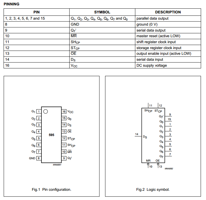
74HC595 - 8 bits shift register
For further information on this component, refer to the 74HC595 datasheet.
PCB
Now that I had aquired more experience in electronics, it was time to replicate this countdown mechanism on a proper PCB for later integration on my puzzle box. The design work has been performed with Eagle sowftware, PCB was then laser cut, and components soldered.
 |
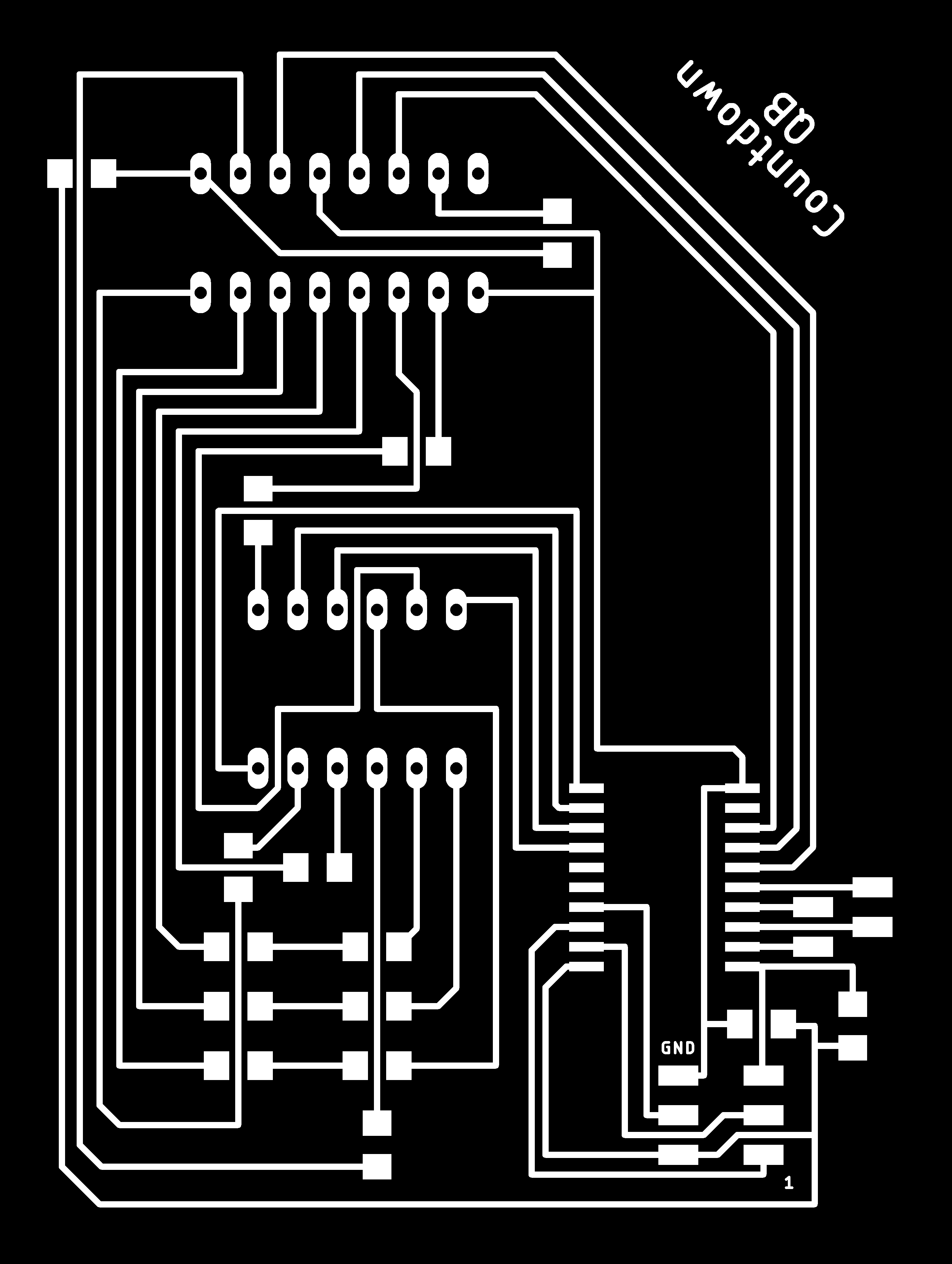 |
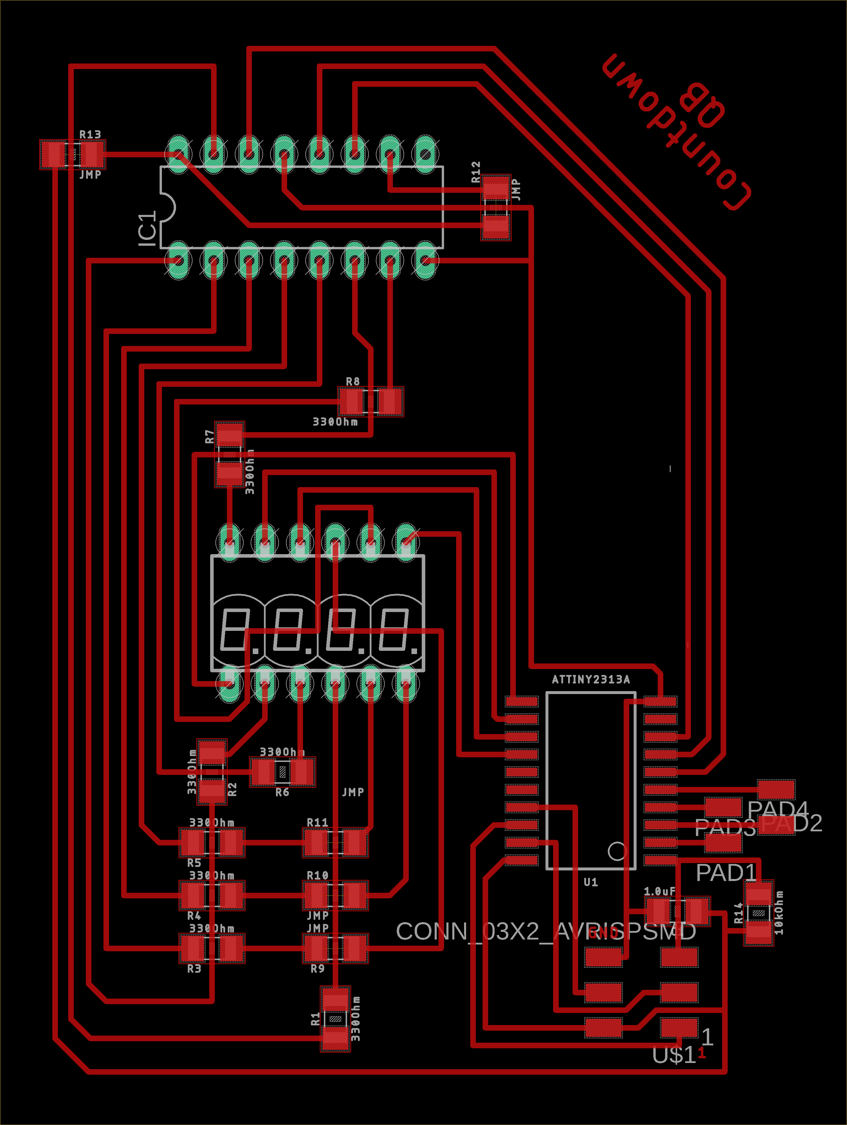
| Countdown PCB - Eagle | Countdown PCB (traces export) - Eagle |
Few comments about this design :
- As I only have one 8 bits shift register, and one four 7-segment digits component, I decided to not solder them directly into my PCB, but instead to use intermediate connectors so that I could easily take those components back in case something went wrong with this PCB.
- For integration of this PCB in my puzzle box I judged it more appropriate to fit the 7-segment digits display at the back of the PCB. As at fablab Digiscope we laser cut the PCB rather than milling them, I had to drill the holes for the through all components manually with a Dremel. With 12 holes to drill, I was afraid to make one mistake that would screw up my whole PCB, but it went fine ! Also, as we only have single sided FR4 copper plate, I had to mirror the 4 digits component pins connections in my design.
- The PCB design presented above integrates some changes compare to the real PCB that is presented in this section, and result from my testing activities :
- 10 kOhm resistor added between VCC and RST.
- 1uF capacitor added between VCC and GND.
- An inappropriate connection between 2 traces has been removed (more info on this topic further down).
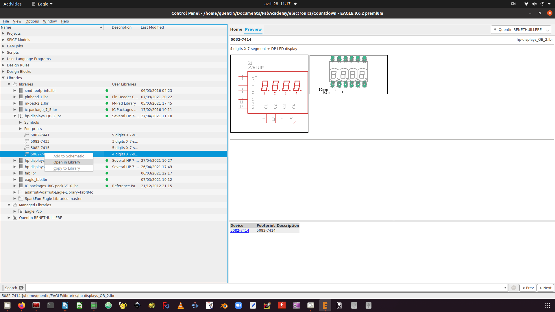
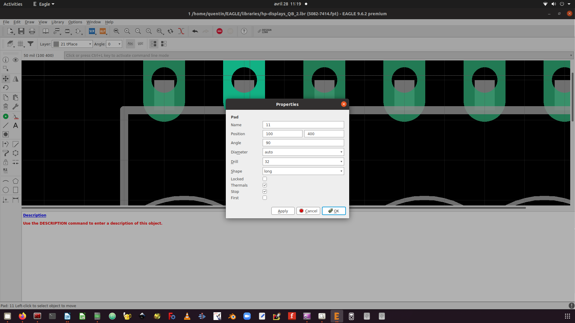
As I could not find the appropriate four 7-segments digits component in libraries, I have customized a similar component and adjusted the pads spacing to my needs. In order to do so, I copied the library where the similar component was located, then opened the component in the library and edited it in the footprint section.
 |
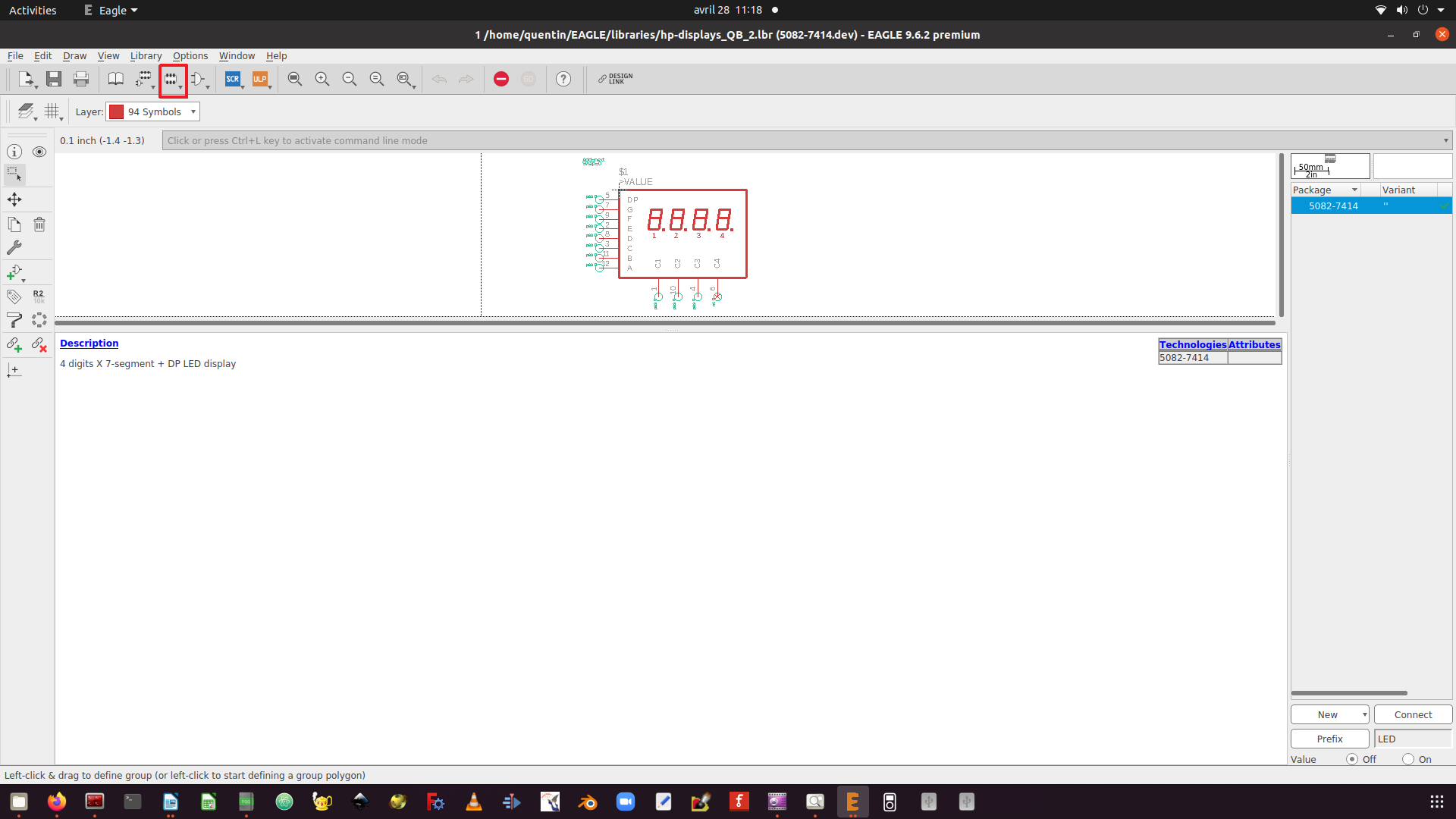 |
| Opening component in library - Eagle | Editing component footprint - Eagle |
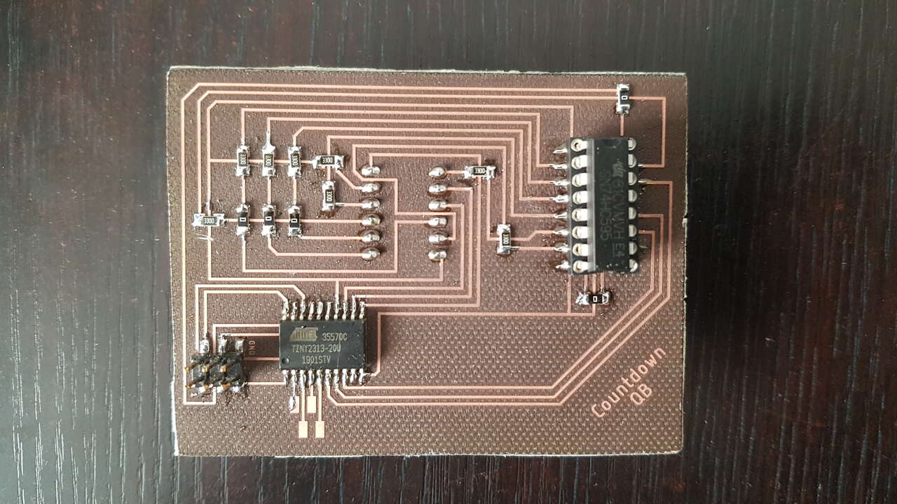
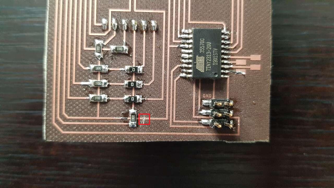
Countdown PCB - front view
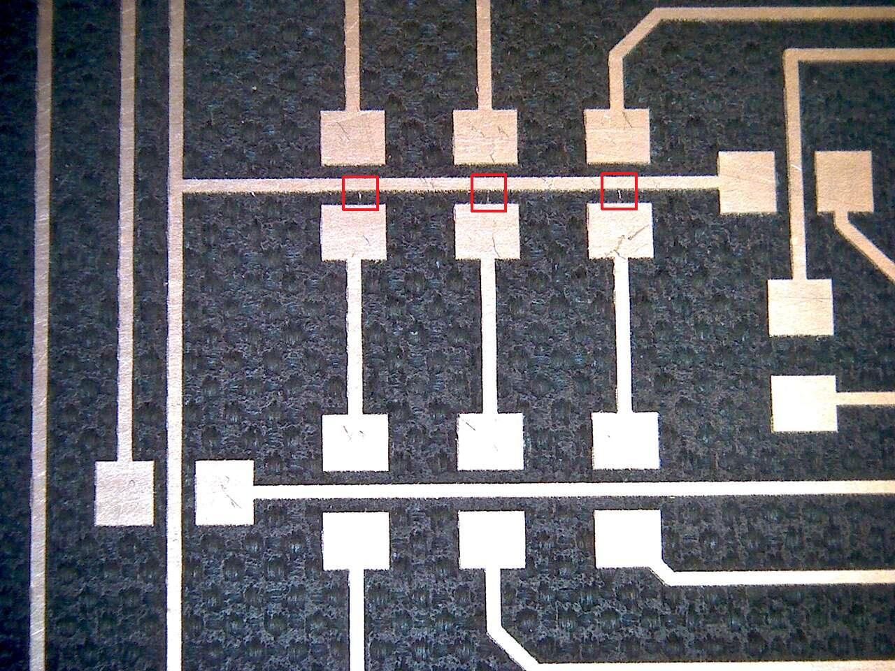
I want to emphasize the importance of using a multimeter to perform continuity tests and looking for shorts on the PCB before soldering electronic components. Indeed, I was happy that I did it because it permitted me to locate 3 shorts that are presented in the left picture below. A simple box cutter allowed me to get rid of those undesired junctions.
 |
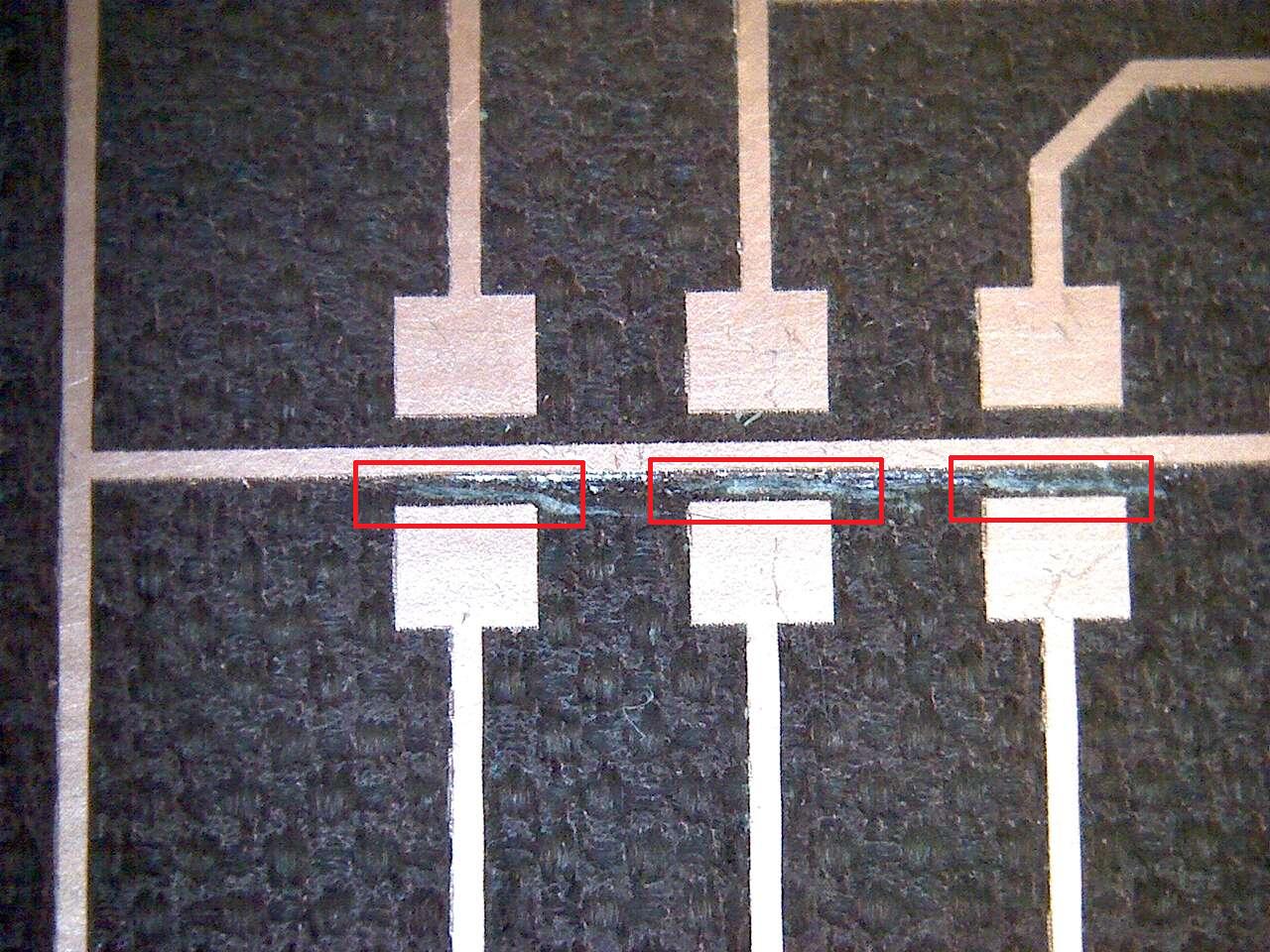 |
| Countdown PCB shorts - electronic microscope | Countdown PCB undesired junctions cut - electronic microscope |
Adjusting pads in component footprint - Eagle
 |
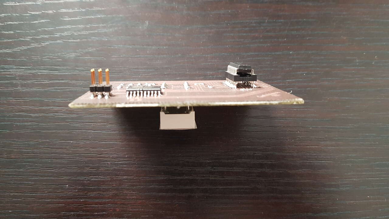 |
| Countdown PCB - back view | Countdown PCB - side view |
After having adjusted the pin numbers in my Arduino program to correspond to the connection established with the ATtiny2313, I could flash the program on the microcontroller, and set the fuses (not dividing the clock by 8) :
avrdude -c usbtiny -p t2313 -P usb:002:007 -U flash:w:4-Digits_7-Segments_Countdown_Flashing_PCB.ino.hex
avrdude -c usbtiny -p t2313 -P usb:002:007 -U lfuse:w:0xe4:m -U hfuse:w:0xdf:m -U efuse:w:0xff:m
Unfortunately the results were a bit weird, and thus I decided to write a debug program that would display every number from 0 to 9 on each digit successively to try to understand what was going on. This permitted me to realize that something was wrong for each digit with the middle horizontal LED (segment G). As one can notice in the below video, digit 1 was never turning on this segment, whereas it was always turned on for digits 2/3/4.
After deeper investigation into my Eagle schematic I understood that this came from an undesired connection between 2 traces that was due to a wrong wire label (that was hidden).
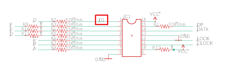
Wire name issue - Eagle schematic view
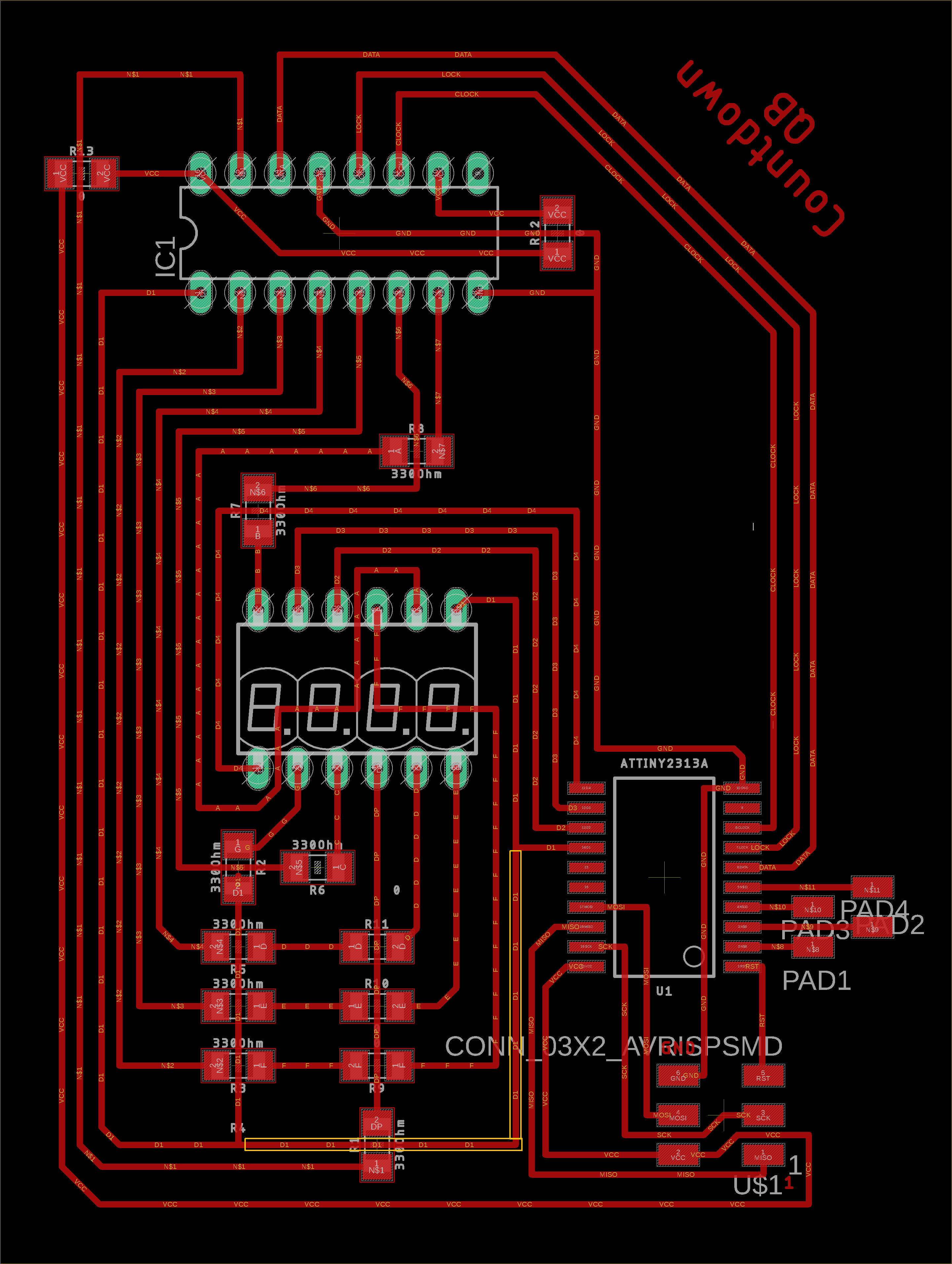
Undesired connection - Eagle board view
After cutting the undesired trace with an exacto knife, I got my coutdown working all fine !
Undesired connection cut
Note: This is a choice I made that the countdown starts flashing when less than a given time remains. This feature, as well as the time at start can be easily adjusted in the software.
Stepper motor control
During the machine design week I had the opportunity to discover how stepper motors work and learnt how to control them with a TinyG (hardware v8) multi-axis motion control system. Four Nema 17 stepper motors have indeed been used to control our drawing machine (1 motor to control motion along the x axis, 2 motors to control motion along the y axis, and one motor to control pen lifting on the z axis).
I just present here a few pictures/videos of those motors in operation, but much more information can be found on the page mentioned in the beginning of this section.
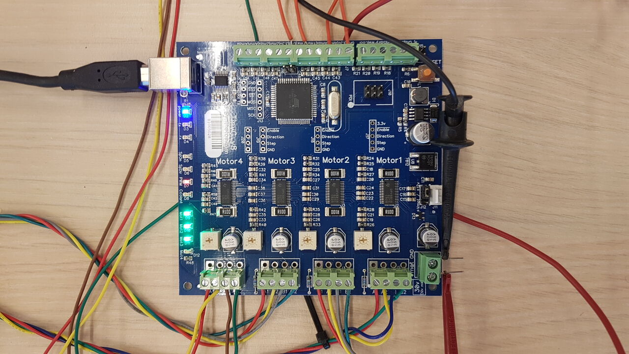
TinyG connections
L293D motor driver
Although I did not perform any test with the L293D motor driver this week, I have been curious to understand how it works. In order to do so I have read this “electrotoile” tutorial (in french) and this “mytechtutor” tutorial.
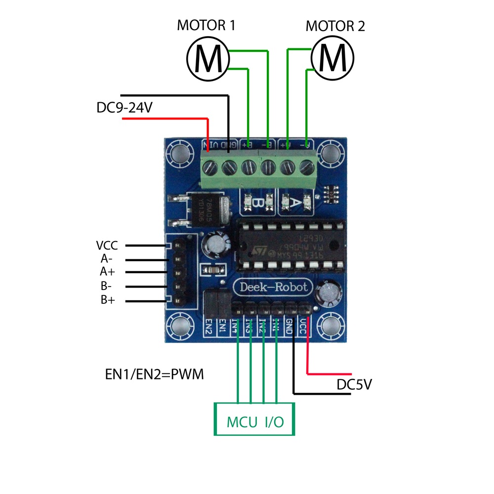
L293D motor driver
Among the most important things to remember :
- The L293D motor driver can drive either 2 DC motors or 1 stepper motor.
- To control DC motor speed : need to connect the EN pin to a PWM pin. Depending on the duty cycle of the pulses generated on that pin, the motor will run faster or slower. Digital pins IN1 / IN2 / IN3 / IN4 are only used to control the direction of motors rotation.
- To control stepper motor speed : set the EN to 5V to always enable the motor, and just increase the frequency of the pulses sent on the IN1 / IN2 / IN3 / IN4 digital pins. Indeed the motor will move one step per pulse on those IN pins, so increasing the pulse frequency increases the speed of rotation.
Group assignment
For the group assignment we have analyzed the current consumption of various electronic components with a Keithley DMM7510 Graphical Sampling Multimeter.
Additional information can be found in our group page.
Source files
The source files of the work presented in this week assignment are available for download here :
- Countdown PCB : Eagle design
- Countdown program : Arduino code / hex file
- DNA access code program : DNA_code_LCD_i2c.ino