8. Computer controlled machining
group assignment
Test runout, alignment, speeds, feeds, and toolpaths for your machine
individual assignment
Make something big
| Documentation | |
|---|---|
| 1. FusionFile | 2. TestFiles.dxf |
| 3. DesignFiles.dxf | 4. AllParts.dwg |
This week I’m going to learn how to use a CNC milling machine and make large format machining jobs.
8.1 Group assignment
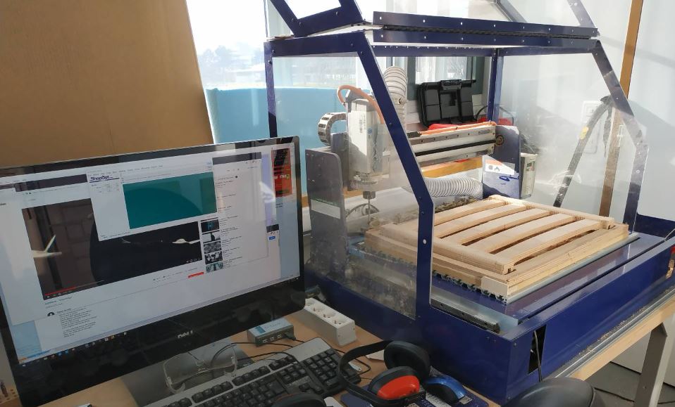
The machine
For this group assignment we learnt how to use the CNC router. We have in the lab a desktop shopbot. We can machine with it stocks of 600x450x40 mm.
The material we can machine
This machine can handle soft materials like :
- wood
- plastics
- some composites
- foam
- …
We can go up to machining aluminium but there’s lots of vibrations involved and this is not this machine first purpose.
Making the path
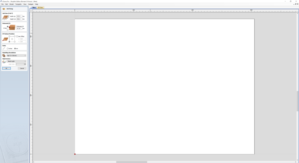
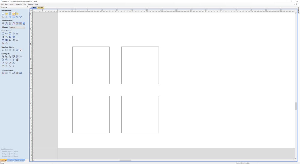
To use this machine, we used the software V-carve. We can import in it a file in vector format (svg/dxf) so we can make our design in Fusion 360, Autocad, Inkscape, Coreldraw … The input format is the same that for the lasercutter. There is also in V-Carve an interface to draw our model.
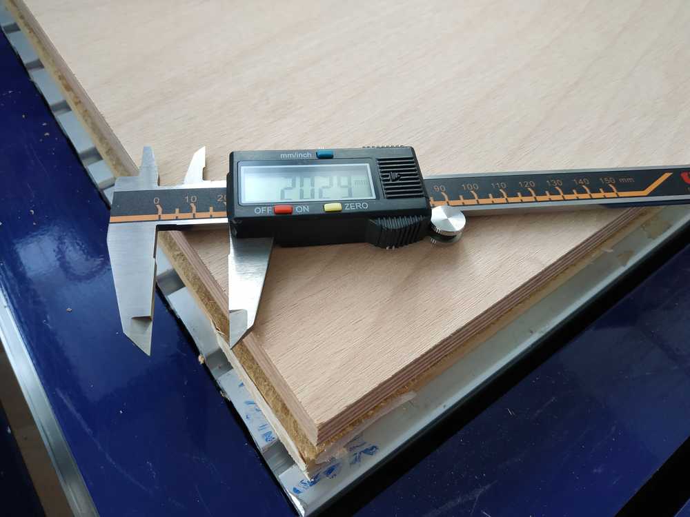
For this first test we used only V-carve. The first step is to define the workspace we are going to work on including the size of our stock (here a 610 x 460 x 20 cm beech wood plank), the origin of the job, and the units we’re going to use . Once this is done, the drawing interface opens. For our tests we decided to go for a square of 5cm to test the different options. This is where you can upload your design.
 |
 |
 |
 |
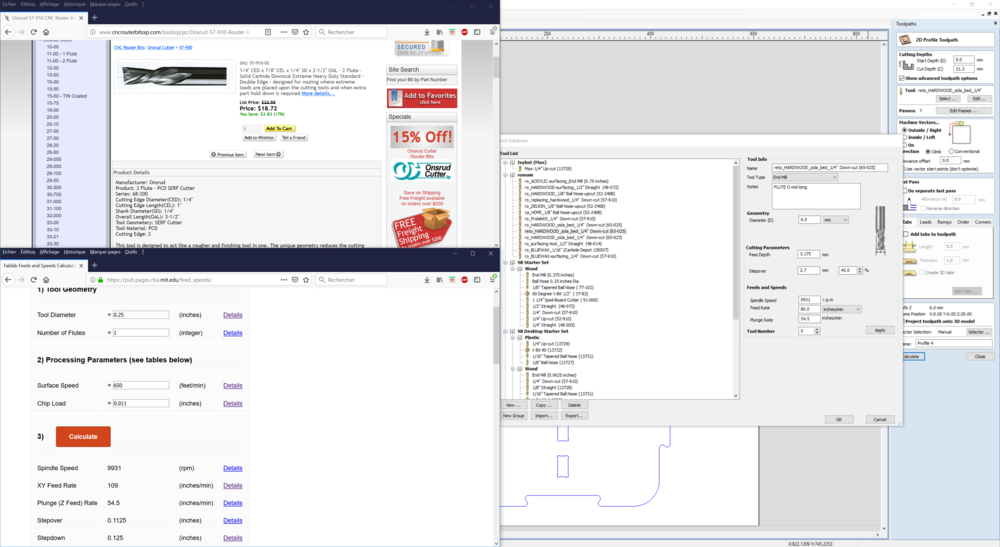
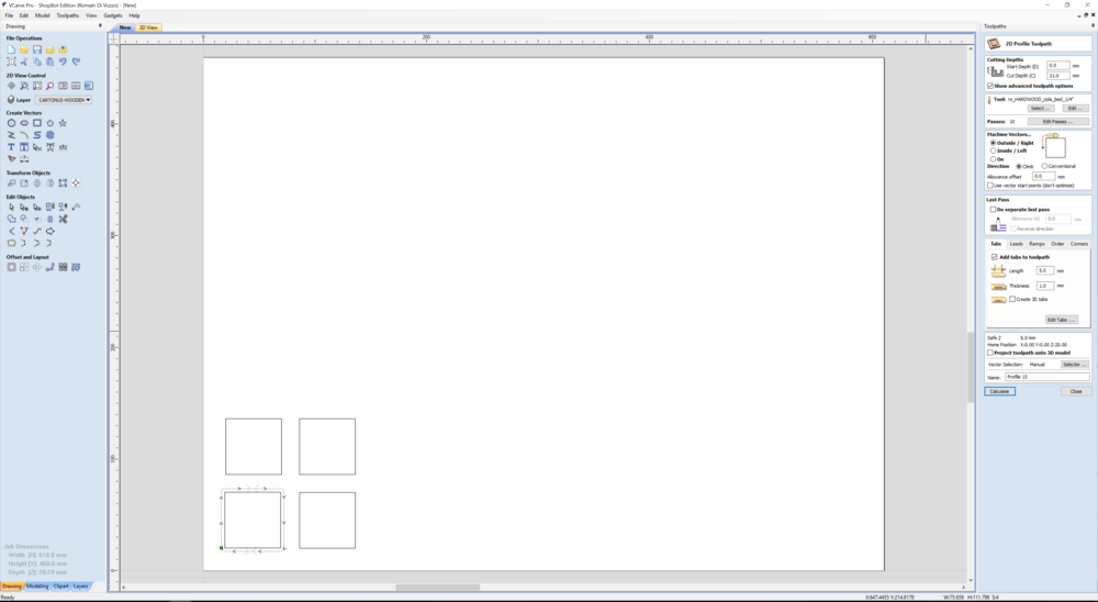
Once the model is clear it’s time to give to the software all the informations it needs to run the job. All those settings are to be filled in the toolpath section. The first thing to do is to tell which kind of bit we will be using. Thanks to the bits datasheet we know the important specifications of our end mill :
- Tool Diameter
- Number of flutes
- Chip load
Using this website we can define the surface speed and calculate the important settings for milling our stock such as :
- Spindle Speed
- XY Feed Rate
- Plunge (Z Feed) Rate
- Stepover
- Stepdown
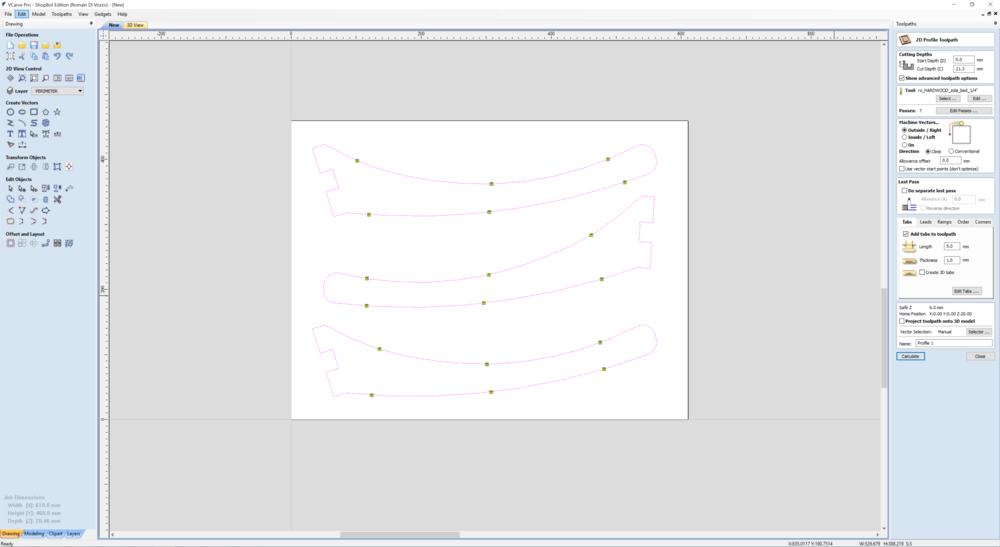
Then we defined what kind of job we want to make. Here we used a 2D Profile Toolpath as we want the end mill to follow the path we made. We could have also used pocket to make forms not going through the whole stock.
NOTE : We can also upload STL file and make 3D machining (it will be useful later for modeling).
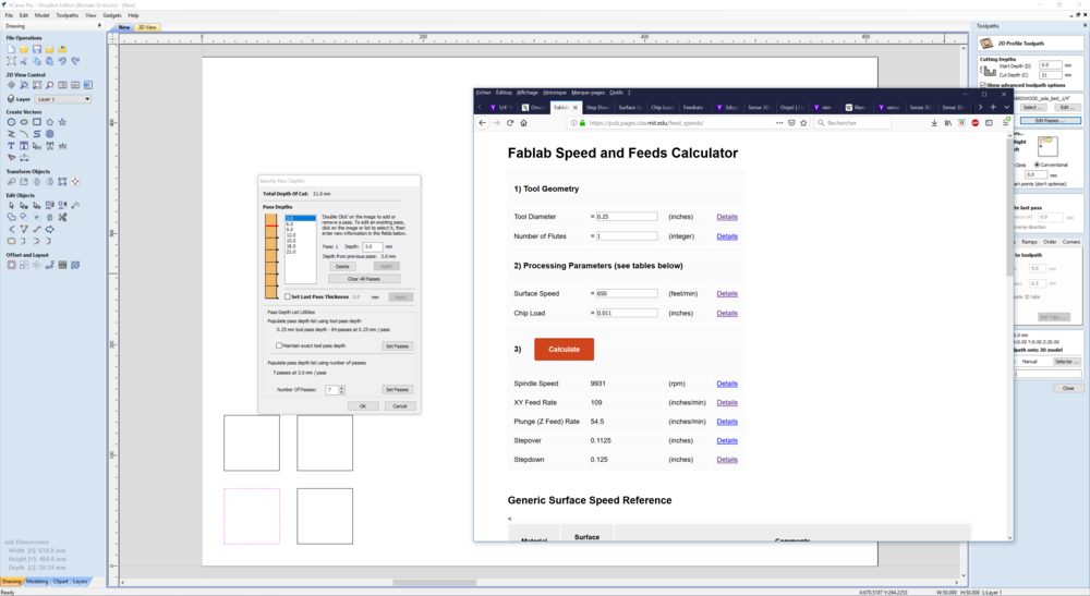
Then we enter some more settings :
- Cut depth : We go a bit deeper than our actual stock (about 0.7mm) because the stock may not be flat and we want the bit to go all the way.
- Number of passes : We select the number of passes we want to have. The more passes, the more time but the less load for the machine. We adjust the value to have a depth of pass just below the stepdown we calculated before.
- Machine Vector : Here we select if we want the bit to go inside, on or outside the path depending of our need. We also select the direction we want the bit to go : climb or conventional.
- Tabs : We add tabs to let a connection between our model and the stock to prevent it to move as the machining ends.
- Ramps : We add the opportunity to the bit to go down into the stock not vertically but in diagonal. It permits to have less load to it.
We better check twice these settings as it’s easy to fail a job if one setting isn’t tuned right.
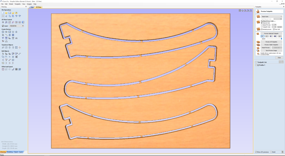
There is an option to preview the job we want to make. If everything looks right, we can then move on and prepare the machine.
 |
 |
 |
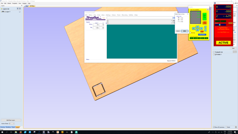 |
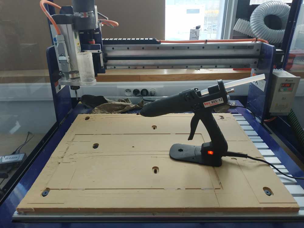
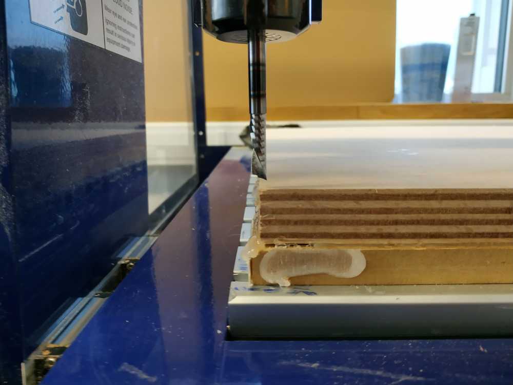
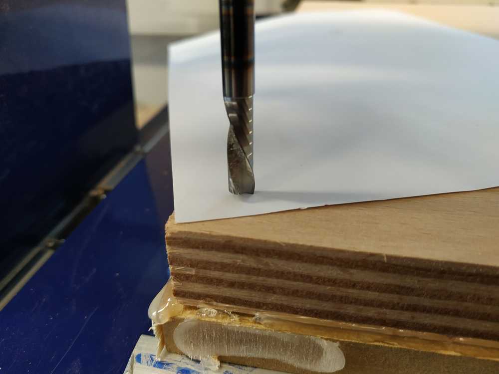
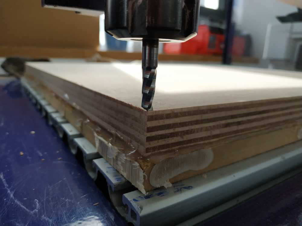
Preparing the machine
Here we have to fix the stock on the bed and define the X,Y and Z origin.
To fix the stock on the bed, we use hot glue all over the stock. Then we manually move the machine with the end mill on and place it exactly on the surface of the stock at the bottom left of it (as we defined it earlier). In the machine controller, once we placed the machine in the correct position, we can then set the origins. When all of it is done, we can upload the file generated earlier by V-care and start the job.
 |
 |
 |
 |
 |
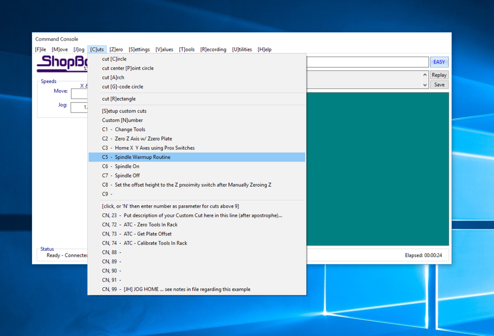
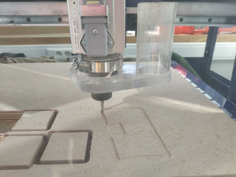
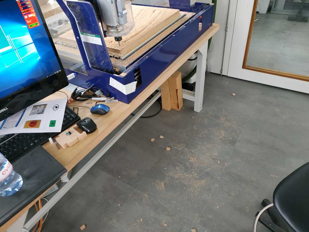
Machining
Before starting the machine there is a Warmup routine for the machine to do. We can start it directly in the Shopbot command (C5).
As we start the job, the machine will make sure that the door is closed for safety reason, then it will ask us the settings we have to use for the speed of the spindle. This speed is not set automaticaly but we have to move the potentiometer of the speed variator on the side of the machine. After setting it the machine starts.
The machining process is quite loud so we use ear protection. It’s important to keep an eye and an ear on what’s going on because failure can damage the stock, the bit or the machine. To stop the machine during the process we just have to press the space bar.
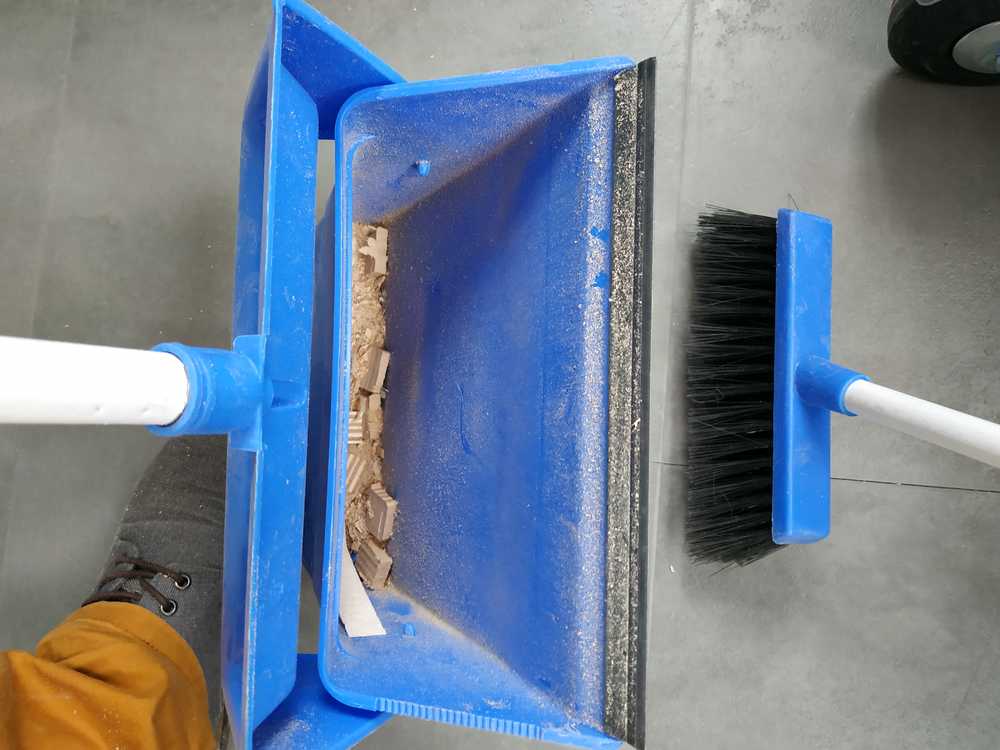
Once the job is complete we wait until the machine goes back to its home position then we can take our parts, remove the stock (if we don’t want to use it more) and use the vaccum cleaner to remove all the dust/wood generated.
 |
 |
 |
 |
 |
 |
Our Tests
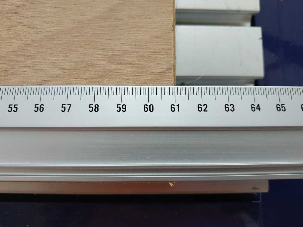
We made many squares to check the dimension accuracy and we found out we were way off (by few mm) and it was not the same offset on both axes. Also the square weren’t exactly the shape they were supposed to be.
After discussing with Romain we made some changes and slowly our results were getting better. Here are the changes we made :
- We found out that using climb direction instead of conventional (for the outside contour) we were getting better shapes but still offsets in dimensions
- We found out the end mill was not so much into the mandrel so we placed it deeper in it and got better results (finally we changed the end mill to one from the shopbot kit)
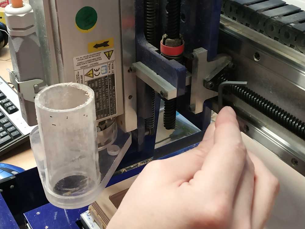
- We found out some screws on the X and Z axes were loose (due to the vibration of the machine probably) so Romain tighten them all.
- We also added more passes (from 07 to 10) so the efforts are less important
After all these modificaions, we found out that the square we cut and the correct shape and where pretty accurate (+/-0.05mm)
 |
 |
 |
We were good to work on our personal assignement
8.2 Personal assignment
I’m going to make something big using a desktop shopbot. I’ll make an assembly of parts with a maximum size per part of 600mm x 400mm. Here I wanted to go with trying to find ideas, I’ve tried few softwares :
- Sketchair
- Slicer
- Fusion Fusion360
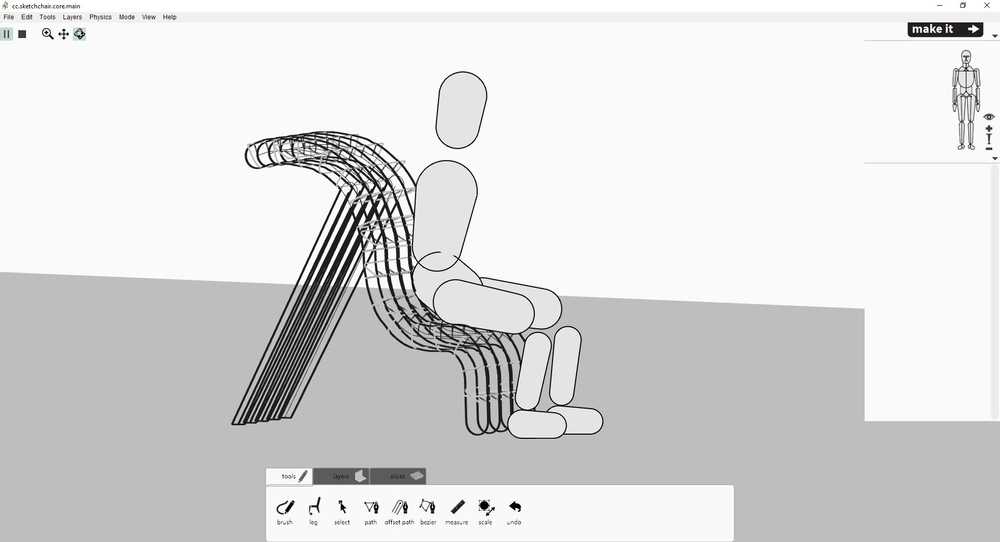
Trying Sketchair
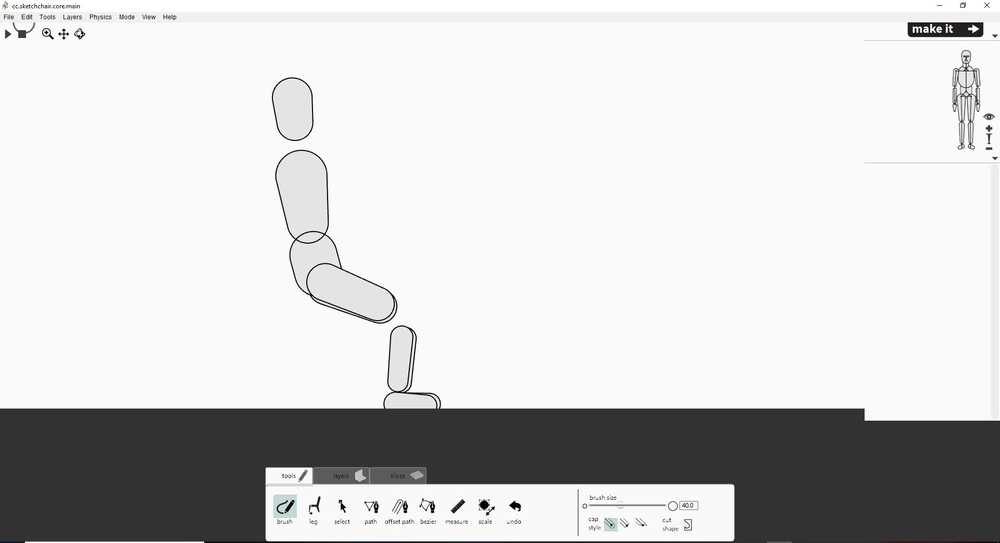
Sketchair is a free software made to design chairs to be cut in a CN milling machine like the shopbot.
After installing the software you have an interface with a human body to have an idea on proportions. Using the Brush command I made a rough shape of a chair. Then using the Leg command I completed the design of the chair. You can then simulate the design to see if the humain sits properly and if everything is stable. Then you can tell how width you want the chair to be. You also select the type of joins you want (chamfer, dog bones …). Once you are happy with your design you can download the file to make your chair.
 |
 |
 |
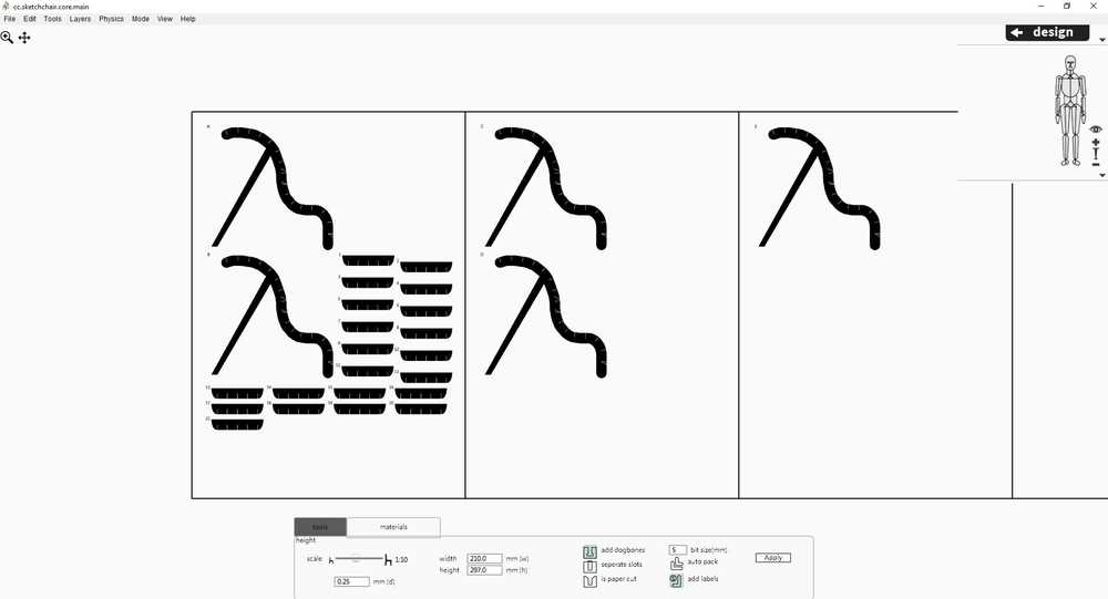 |
I didn’t commit to go further as I thought I didn’t have enough controls on the dimensions and only got a rough design.
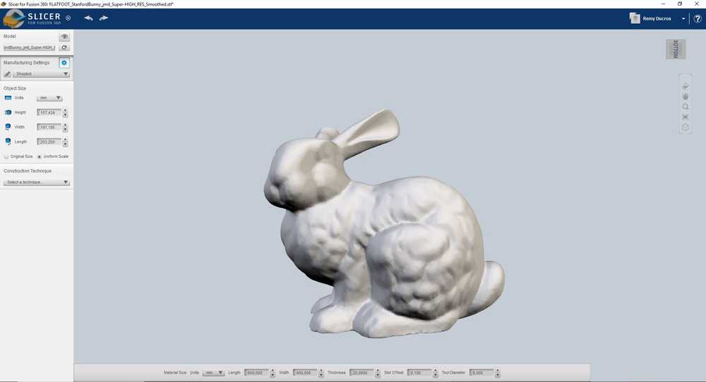
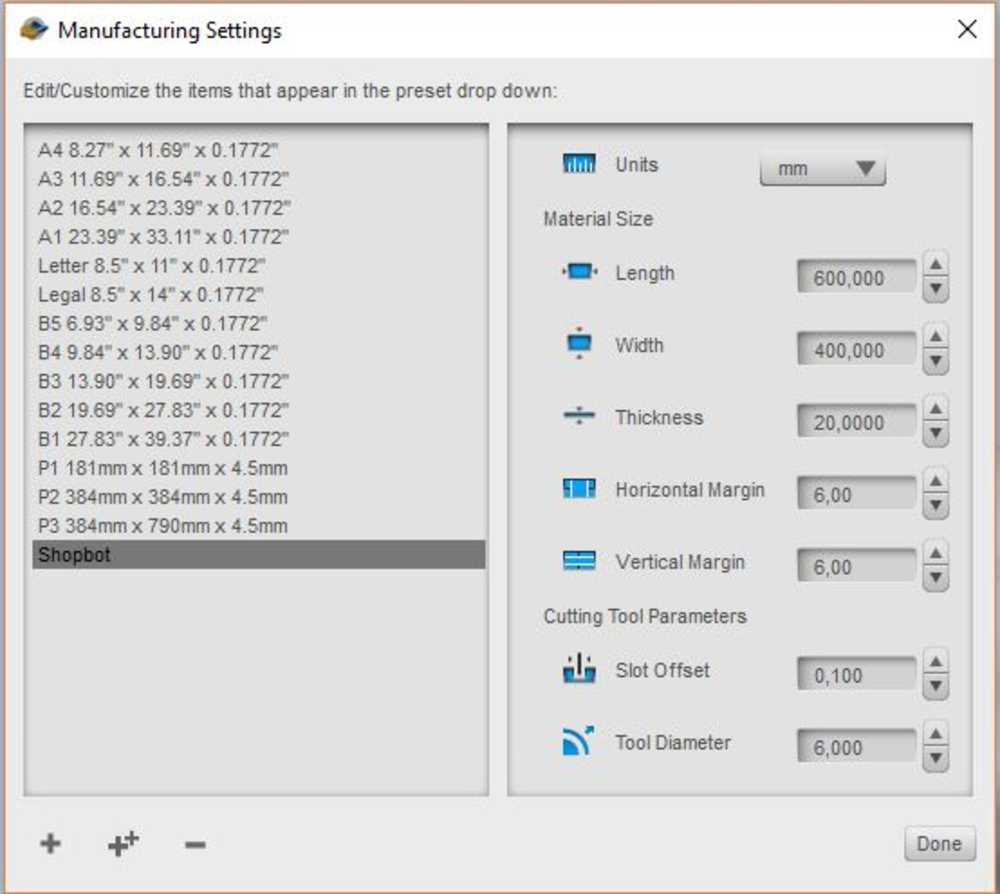
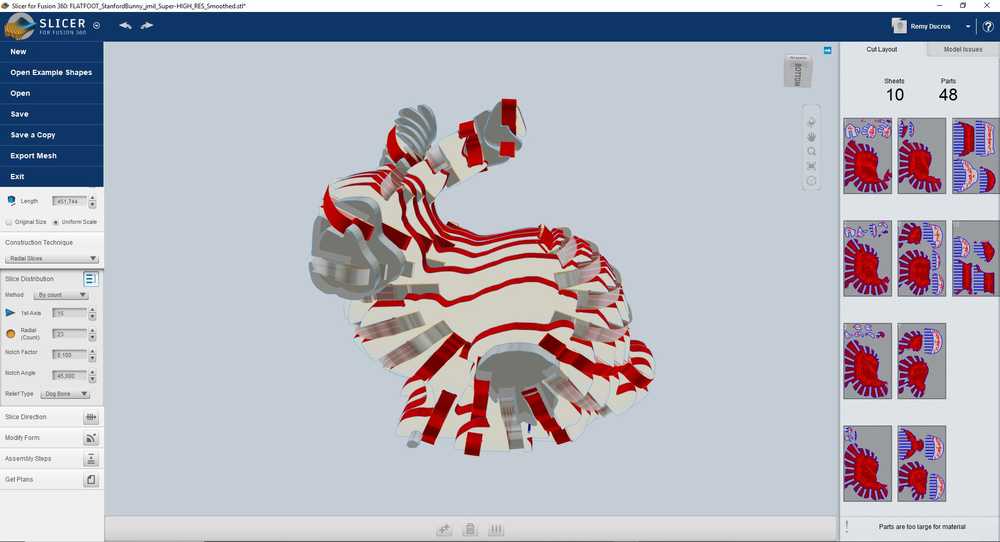
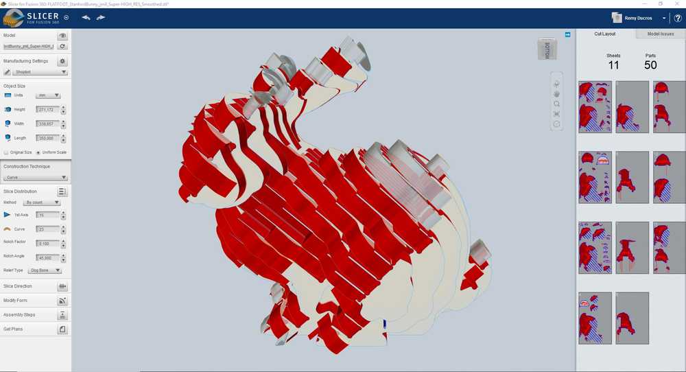
Trying Slicer
Slicer for fusion 360 let’s you transform an STL into slices of material you can then cut and assemble. It’s nice because it lets you make 3D objects using machines used mostly to make 2D models. I wanted to go for a big assembly so I tried to make the Stanford bunny. I uploaded the model into the software then I made a custom setup ; Basicaly making a new setup means informing the software about the size and thickness of your stock. Then, you have many options to slice your model. I tried different settings but I always had issues with my model, due to the thickness of the material I wanted to use I always had unconnected parts. Here again, you can choose the type of join you want (dog bones) and the software will automaticaly save the the different parts ready to cut.
 |
 |
 |
 |
I think the best use for this software is for the lasercutter and thin material (like cardboard).
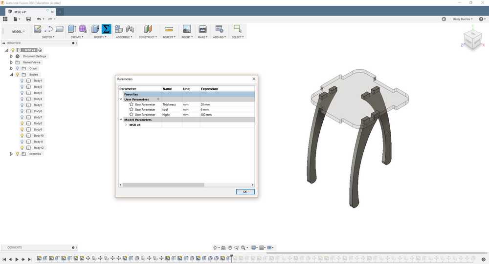
Making my own design
I went back to Fusion 360 with the idea of making a design of a furniture that can be modular and parametric. My idea was to make a module the size of a chair, that can be attached to other modules to be used as :
- A chair
- A side table
- A coffee table
- A bench
- A gaming table
- …
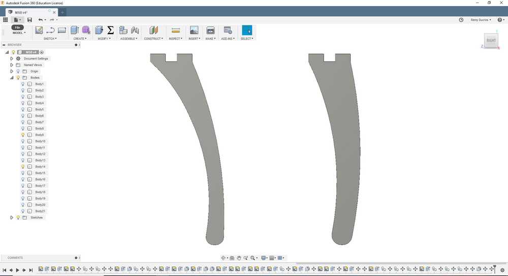
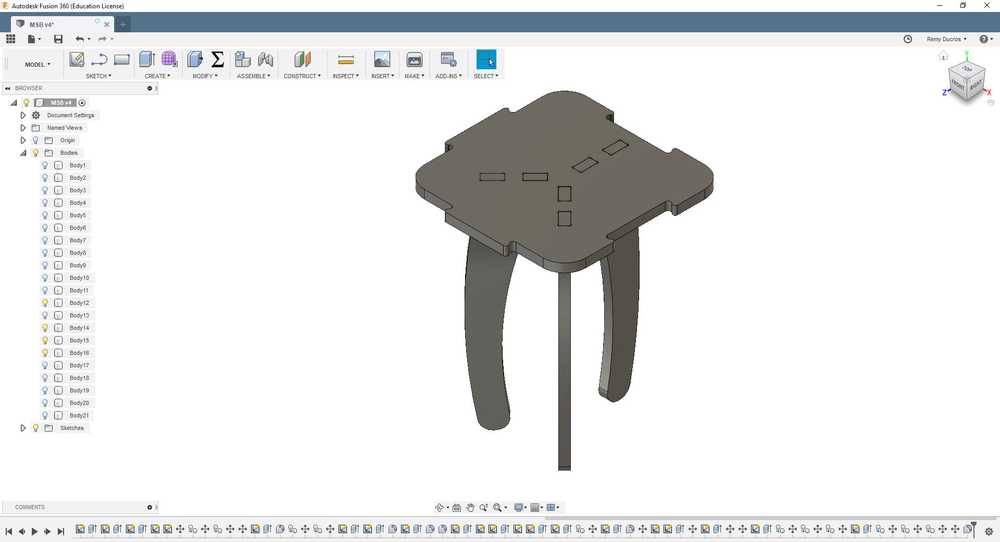
I made this first design. It’s parametric and the parameters are :
- Hight of the legs
- Thickness of the material used
- Diameter of the tool
 |
 |
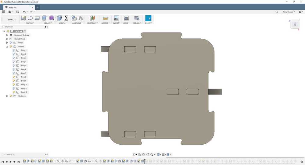 |
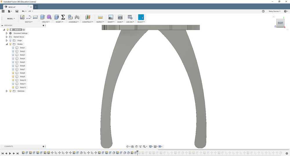
For this model, I follow some design rules :
- I went for a puzzle design to snap the modules together
- I put only three legs so each module is isostatic
- I put one leg on one side and two on the other so the module will be able to snap in all direction without having interaction between the legs
- I designed the legs to be far from one another to have more stability
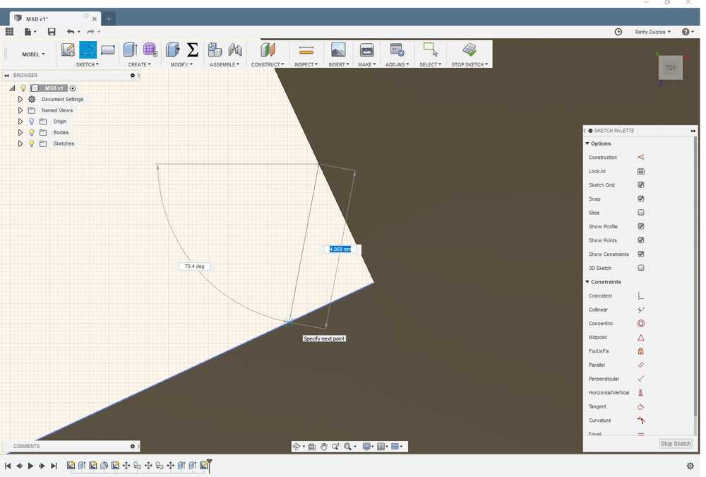
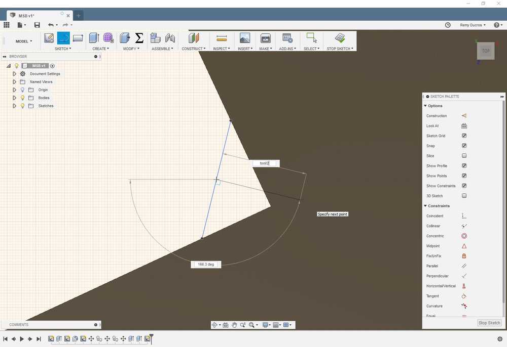
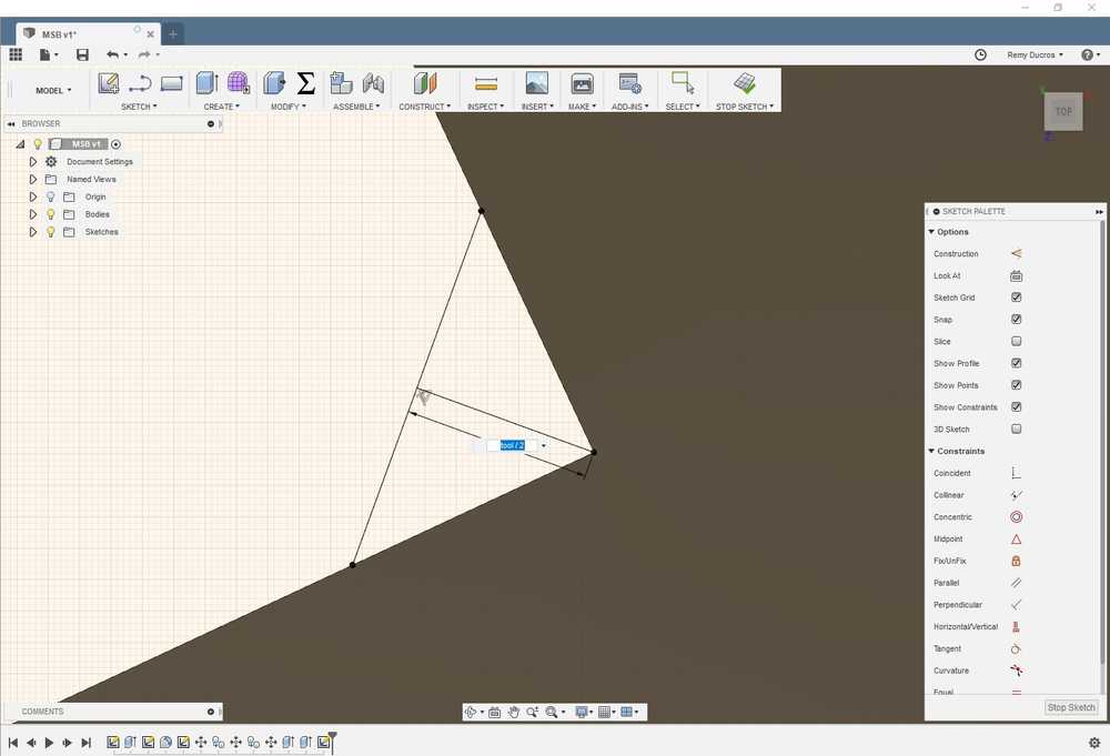
Making the dog bones
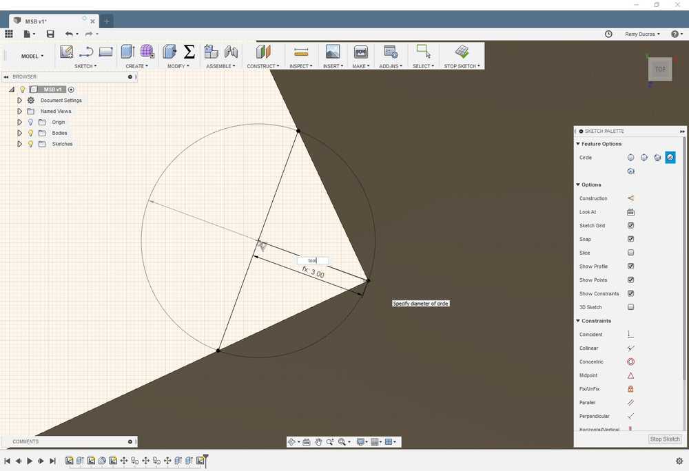
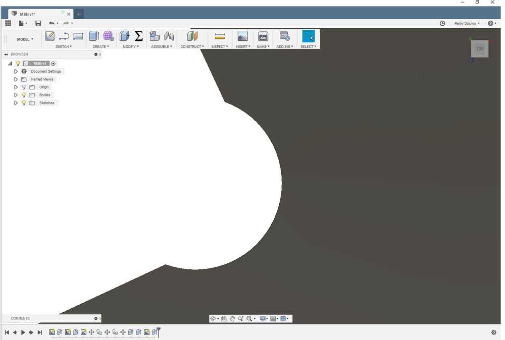
For my design I needed to make some dog bones in order for the part to assemble together. I tried different ways to make the dog bones and here is my way of doing it in few steps. My concern was to use cut as less extra material as possible.
- Select a corner where you want to make the dog bone and draw a segment between each side of the angle. The distance isn’t important but each edge of the segment have to be coincident with the line.
- Draw a mediator of the segment with a length of tool diameter/2
- Make the end the mediator coincident with the corner
- Draw a circle where the center of the circle is the connection point between the mediator and the segment you draw and give it a diameter of tool diameter. You can see your sketch is fully constraints as it’s black.
- Extrude/Cut the circle and here you have your dog bone (and it’s parametric)
 |
 |
 |
 |
 |
Her’s a video of me doing it :
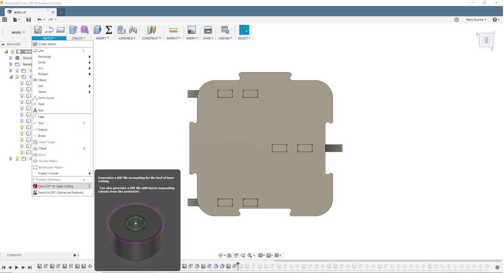
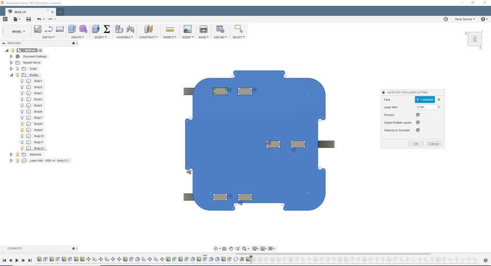
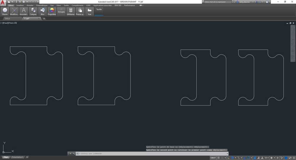
Exporting my design
Once I was done with my design I exported each part using the export as DXF add-on in Fusion. Then I compiled everything in Autocad. I made sure my parts will fit in my stock so I draw the stocks and did some nesting to fit my parts. I found that I needed two stocks to make one module.
 |
 |
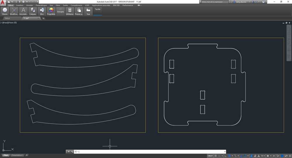 |
Testing my design
Before going for the whole machining of my parts, I wanted to make sure my joins will work just fine. I had two joins to test :
- The connection between the legs and the plate
- The connection between two plates.
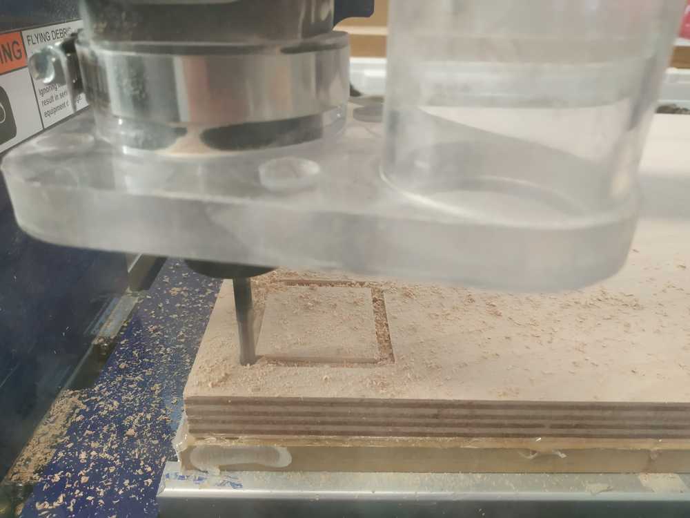
Testing the dogbones connections
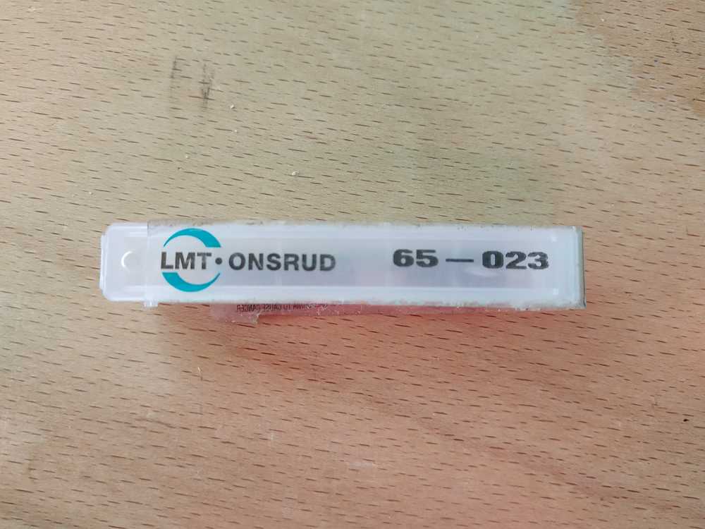
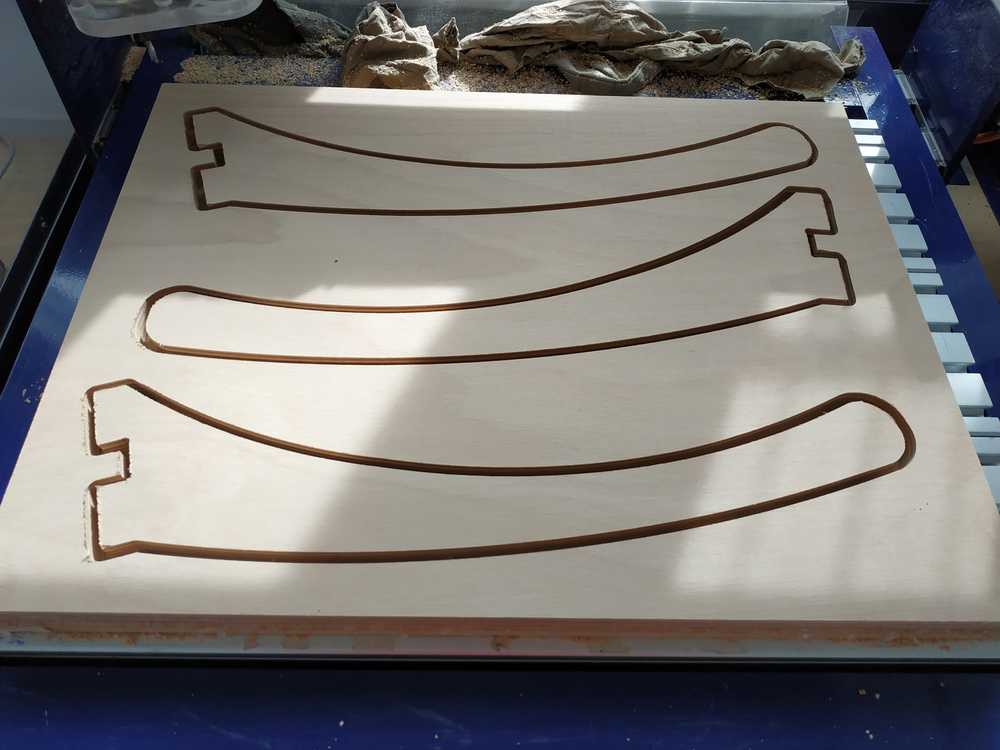
I first decided to machine the connection I will later use for the leg. I used the following settings :
- 2cm thick beech wood plank
- End mill LMT.ONSRUD 65-023
- 2D Profile
- Inside contour or pocket
- Climb direction
- 10 Passes
- Tabs : yes
- Ramps yes
After cutting the first part, I found out out I forgot the dog bones, so I made the modification and I cut the part.
 |
 |
 |
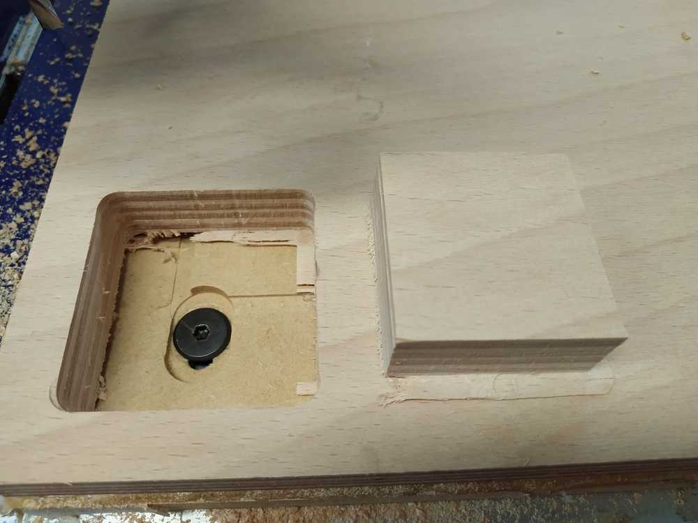
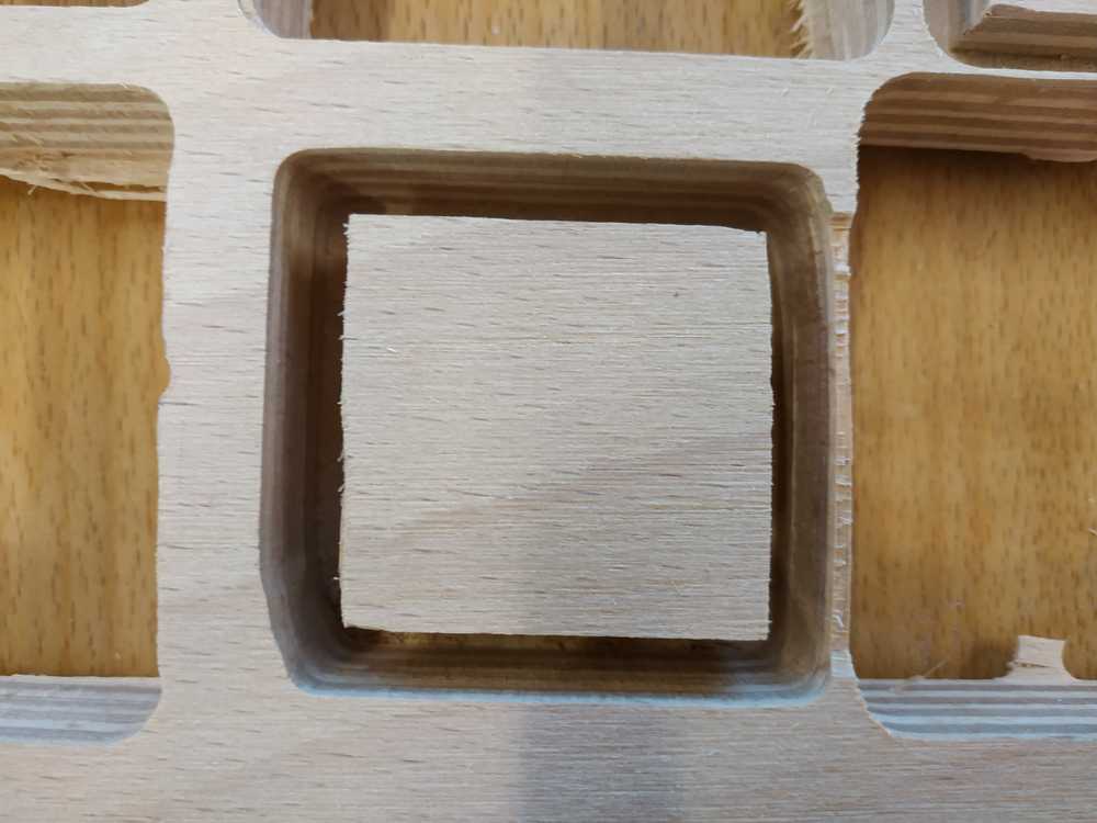
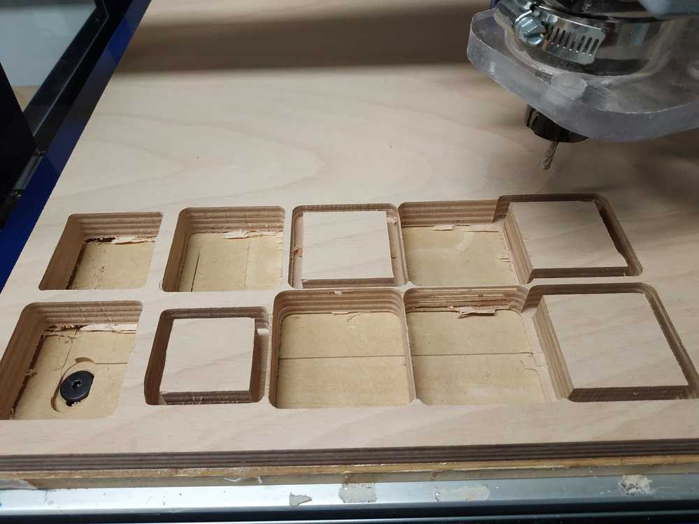
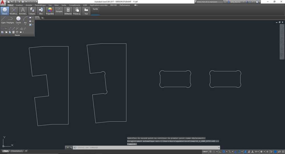
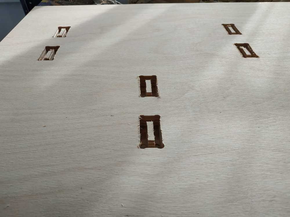
Then I cut the dog bones profiles, I made different tests to make sure it was working fine.
| 0 mm | Too tight | |
| 0,5 mm | Too tight | |
| 1 mm | Too loose | |
| Profile 2D - Inside | 0 mm | Too tight |
| Profile 2D - Inside | 0,5 mm | Too loose |
| Profile 2D - Inside | 0,2 mm | Good |
NOTE : No need to go for pocket here as it takes much more time (around 12 mn, when it takes only 4 mn with the 2D profile) and we can achieve the result we want with a 2D profile.
 |
 |
NOTE : After doing my tests I think that I may have better results for the inside contour if I use the conventional direction.
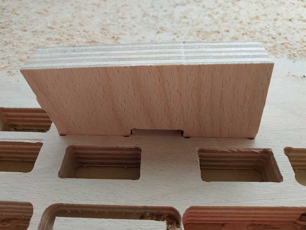
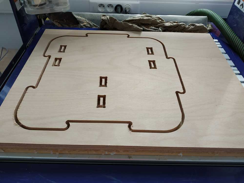
Testing the modules connections
To test the connection between two modules I went for a small version of my design. I then cut two of them using the following settings :
- 2cm thick beech wood plank
- End mill LMT.ONSRUD 65-023
- 2D Profile
- Outside contour
- Climb direction
- 10 Passes
- Tabs : yes
- Ramps yes
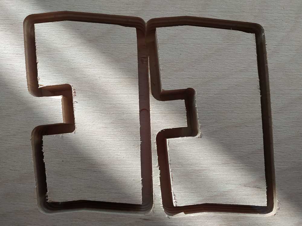
I did three tests :
| Profile 2D - outside | 0 mm | Too tight |
| Profile 2D - outside | 0,1 mm | Too tight |
| Profile 2D - outside | 0,2 mm | Good |
NOTE : Making the second test, the endmill got stuck in the wood and I had to stop the machine. I think it happened because my two parts where too close from one another.
 |
 |
 |
After all these tests I made the adjustments in my design and prepared the machine to make two modules.
NOTE : I did the offsets using Fusion 360 directly but it’s possible to do it in V-Carve as well.
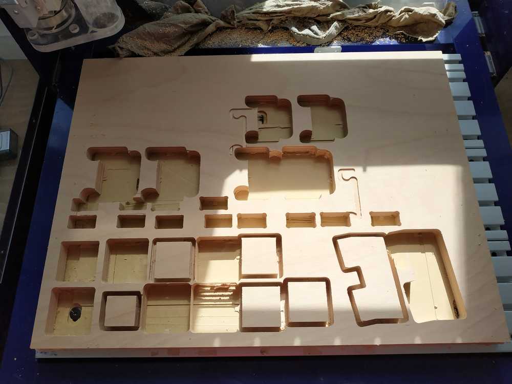
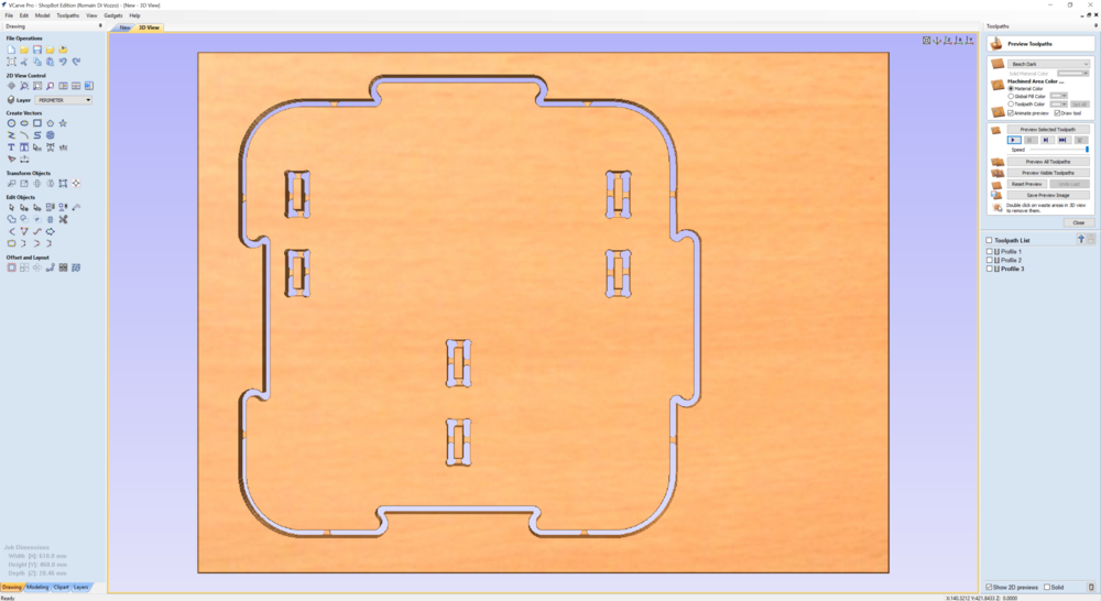
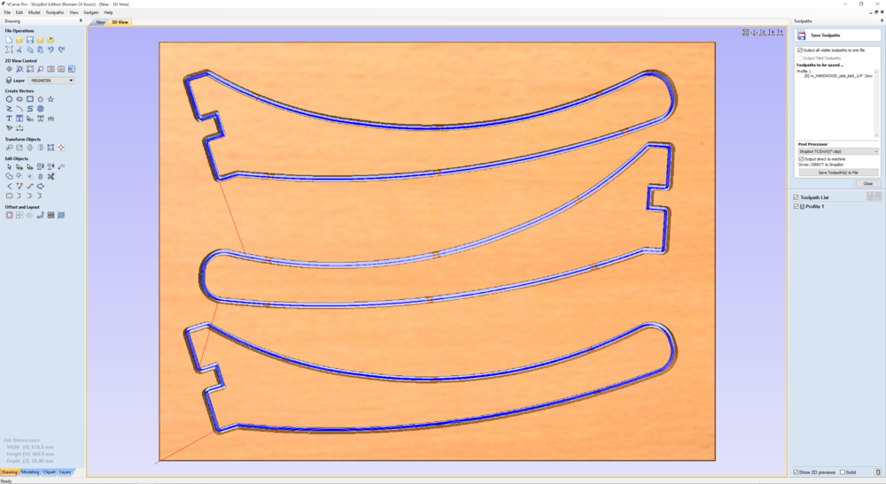
Machining the modules
Confident after my tests I made two modules. Here the steps I followed :
- I exported the profiles from Fusion to Autocad
- I created a new setup in Vcarve where I measured the dimension of my stock
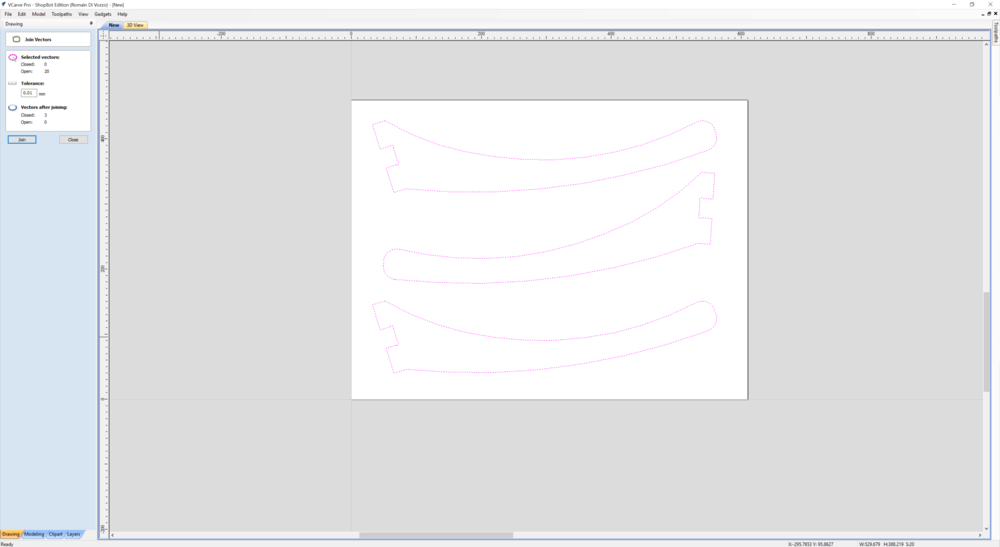
- I upoaded my design and join the different profiles
- I selected the 2d profile
- I selected the End mill LMT.ONSRUD 65-023 with 7 passes
- I selected the settings I’ve found work better
- I simulate the work and saved the code
|
 |
 |
 |
 |
 |
I then prepared the machine :
- I glued the stock
- I made the XYZ origin
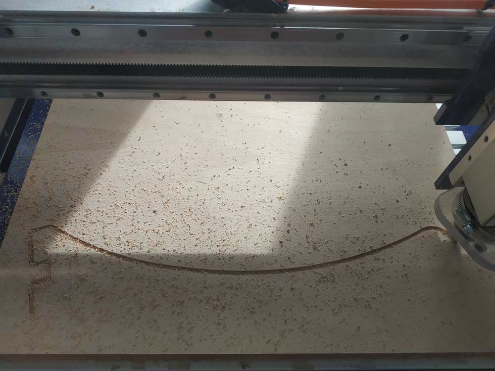
- I machined the plates :
- First the legs (outside contour)
- Then the inside contour of the plate
- Finally the outside contour of the plate
 |
 |
 |
 |
 |
 |
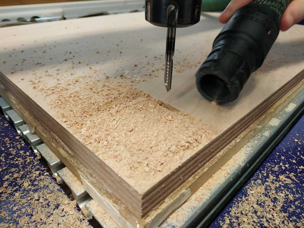
Once I was done I took all my parts and cleaned the place around the machine.
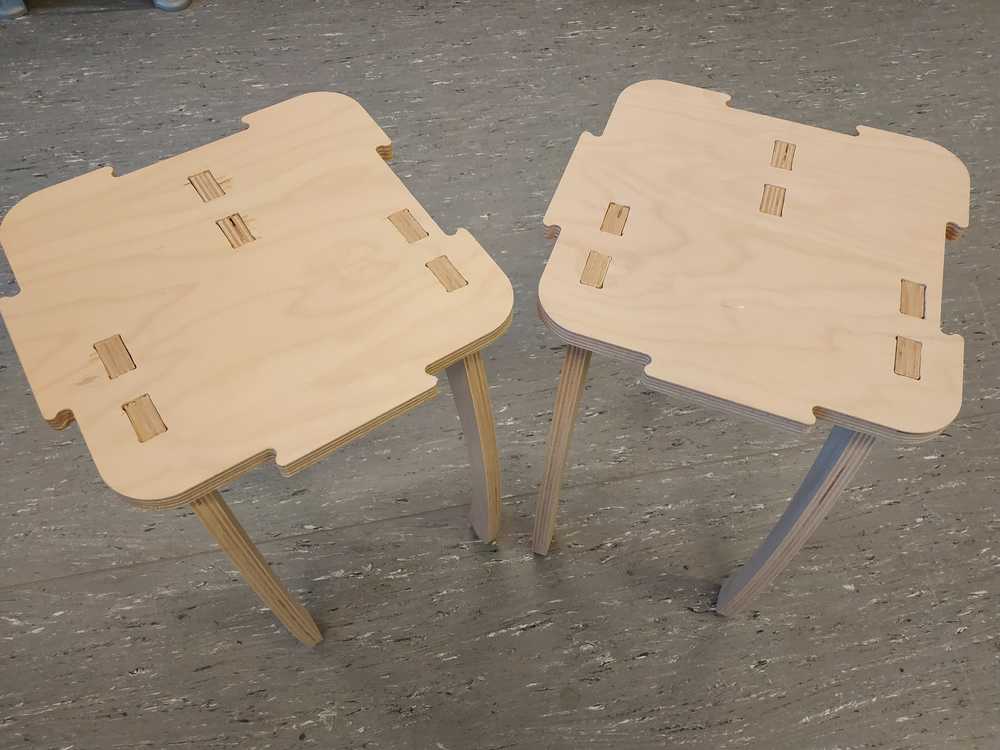
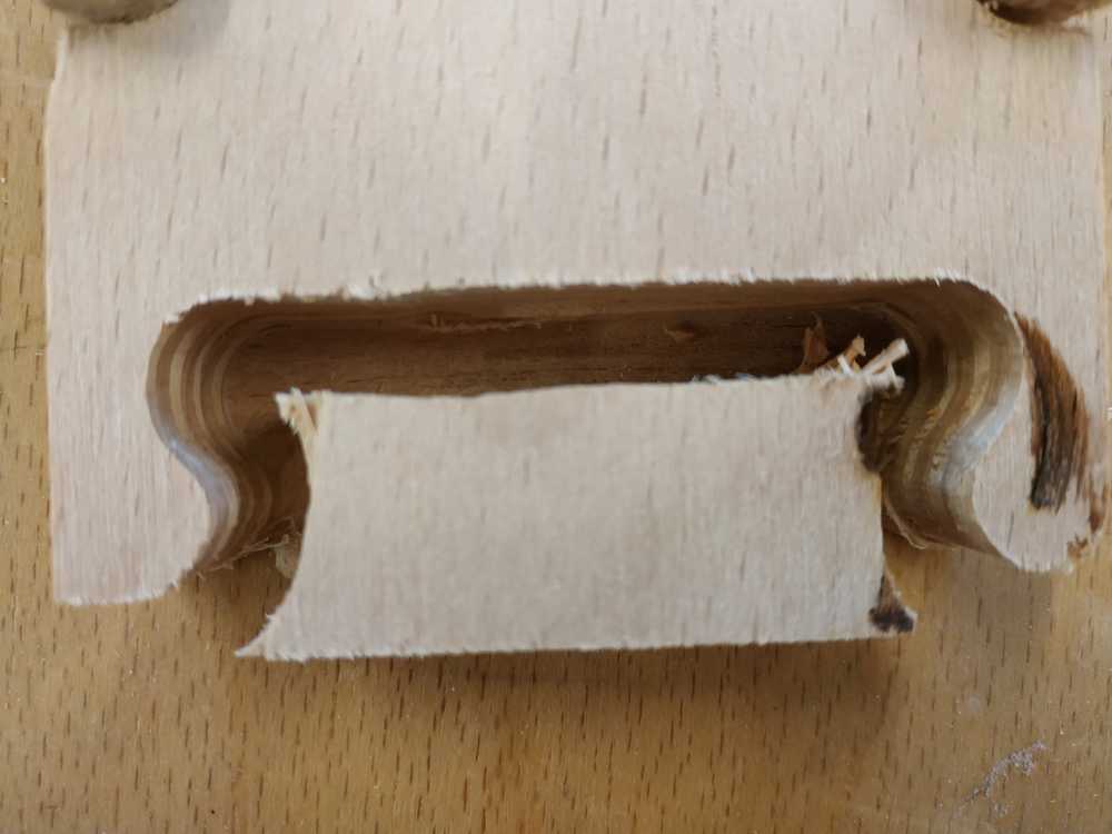
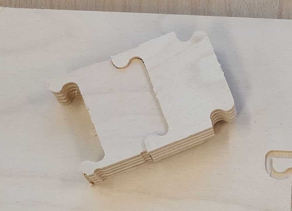
Final adjustment and assembly
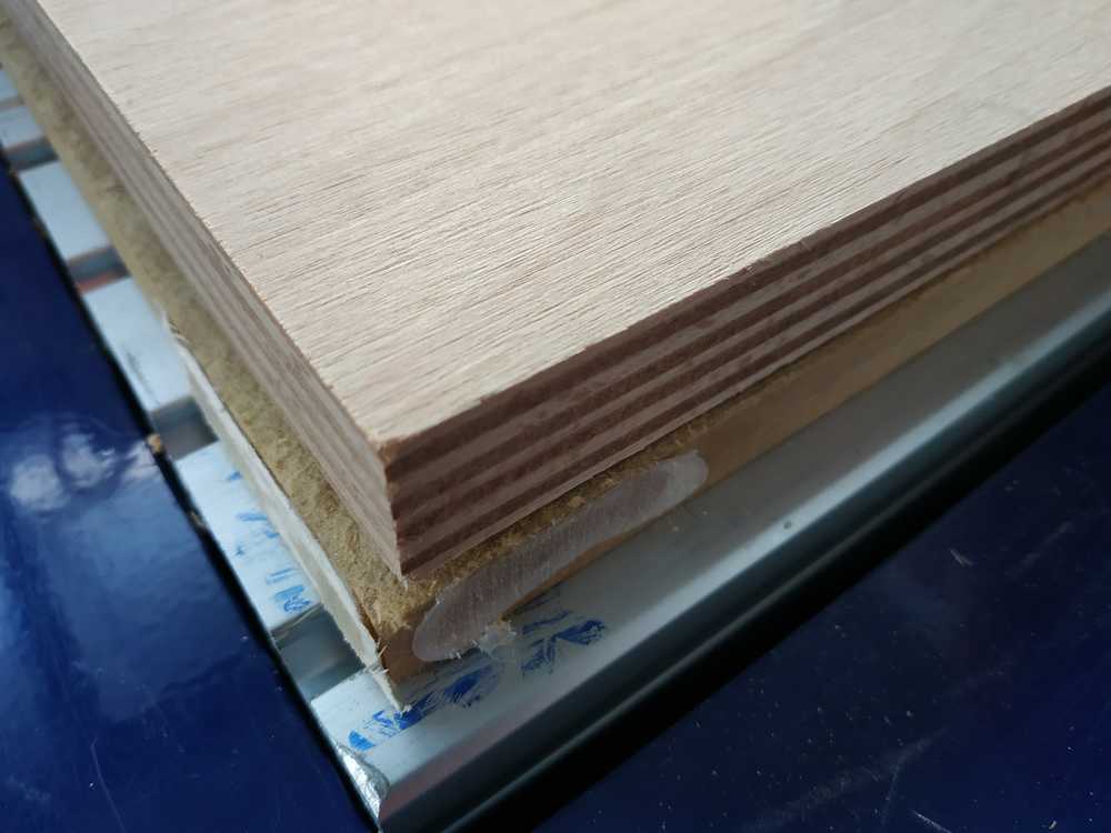
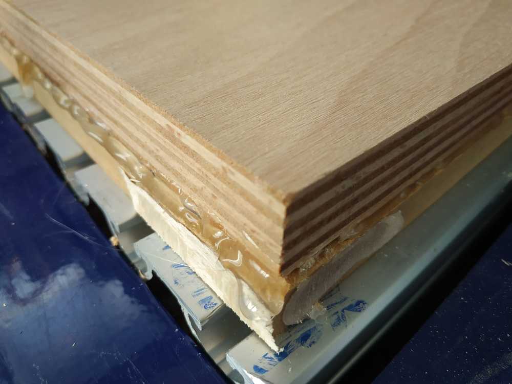
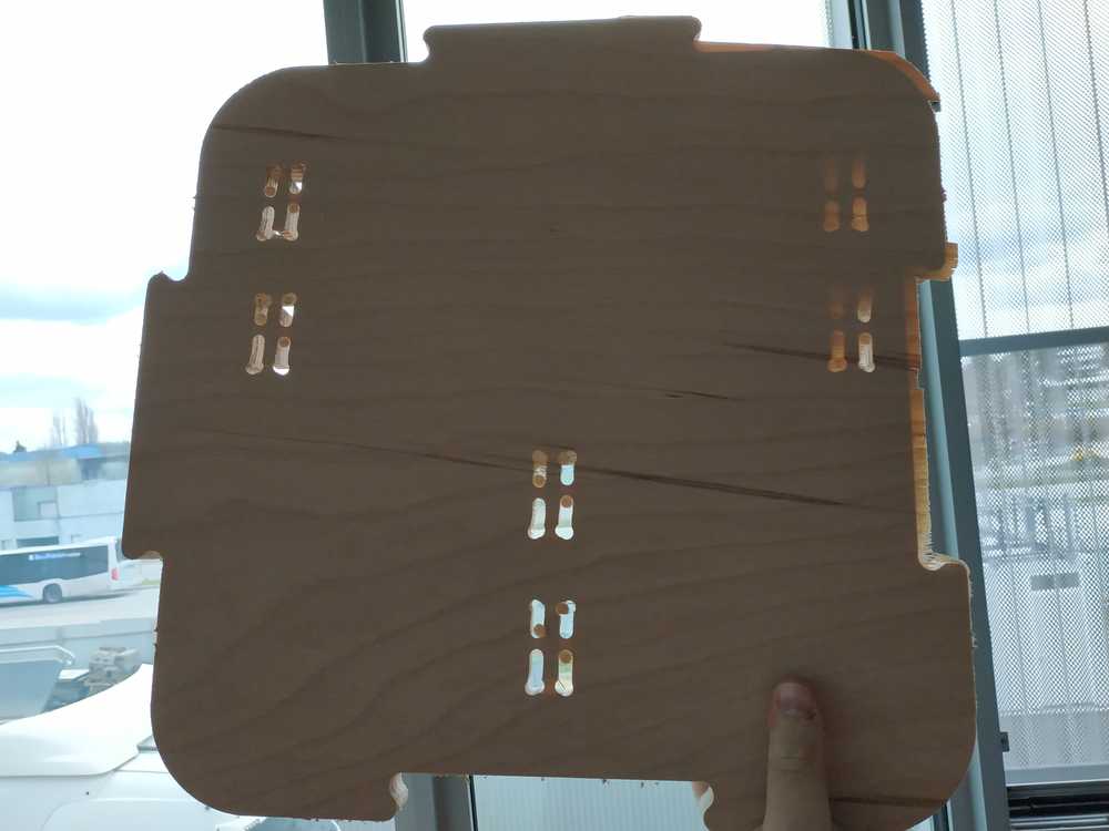
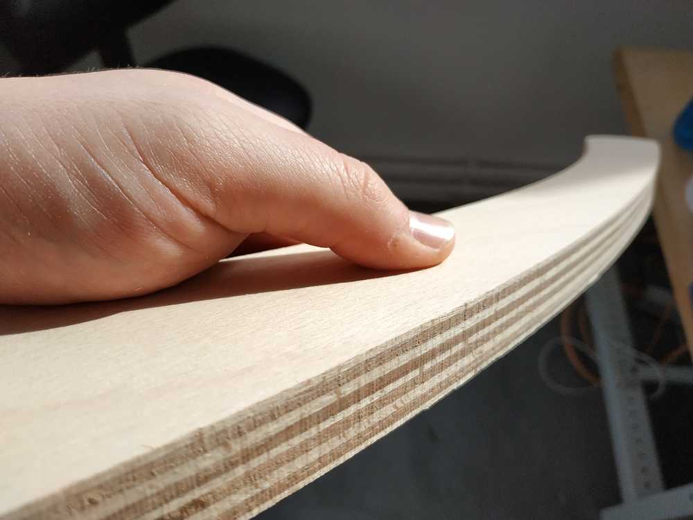
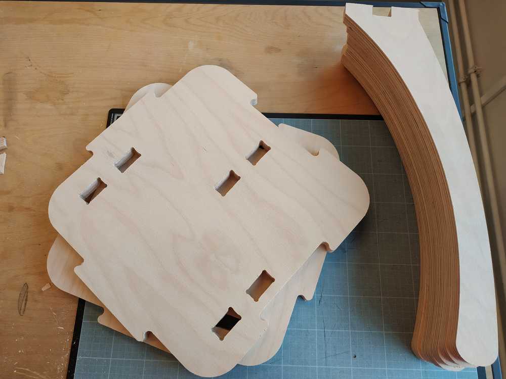
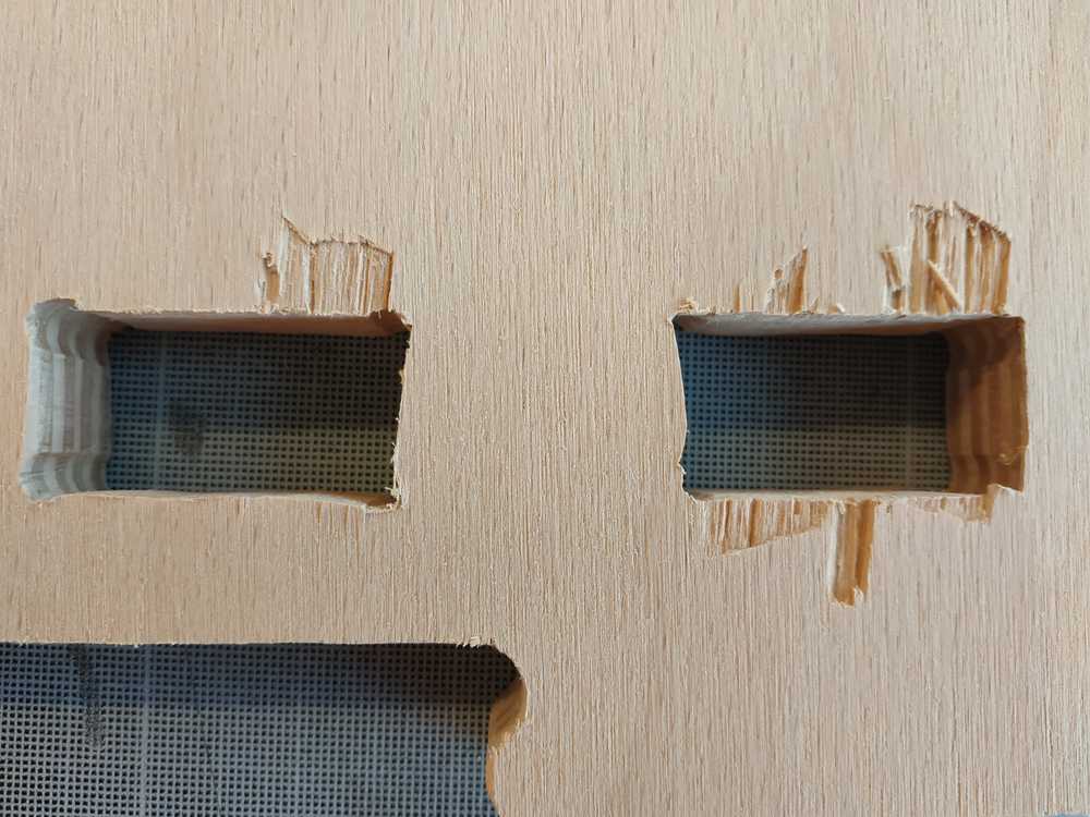
As I removed all the parts, I could make few observations :
- The endmill didn’t cut through all the stock at some points
- We can see some “waves” on the side of the legs, made by the vibrations of the machine
- The shape of some dog bones weren’t so good (I think for inside cut it’s better to use conventional direction)
 |
 |
 |
 |
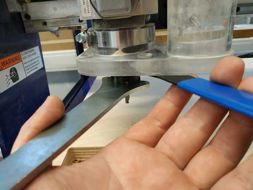
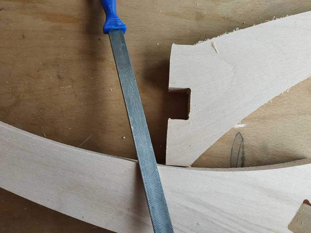
After I removed all the parts from the stock, I used a file to remove the extra wooden part and the tabs. Unfortunately while filling the wood, I damaged the bottom part of my design.
 |
 |
 |
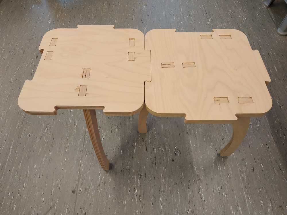
Few observation I made trying to assemble :
- The plates were easy to assemble together (even if it’s a little tight)
- The legs weren’t fitting at all in the bottom side of the plate (too tight)
- The legs fit better on the top of the plate (where the machining starts)
Finally I used a file to loosen the holes and make all the legs fit.
|
 |
Improvement of the design
Testing my design I found some weakness in it :
- The fact that the legs are all in the same direction make the module not stable in the perpendicular position of the legs
- Because the legs go apart from the center makes them want to go away as you put weight on.
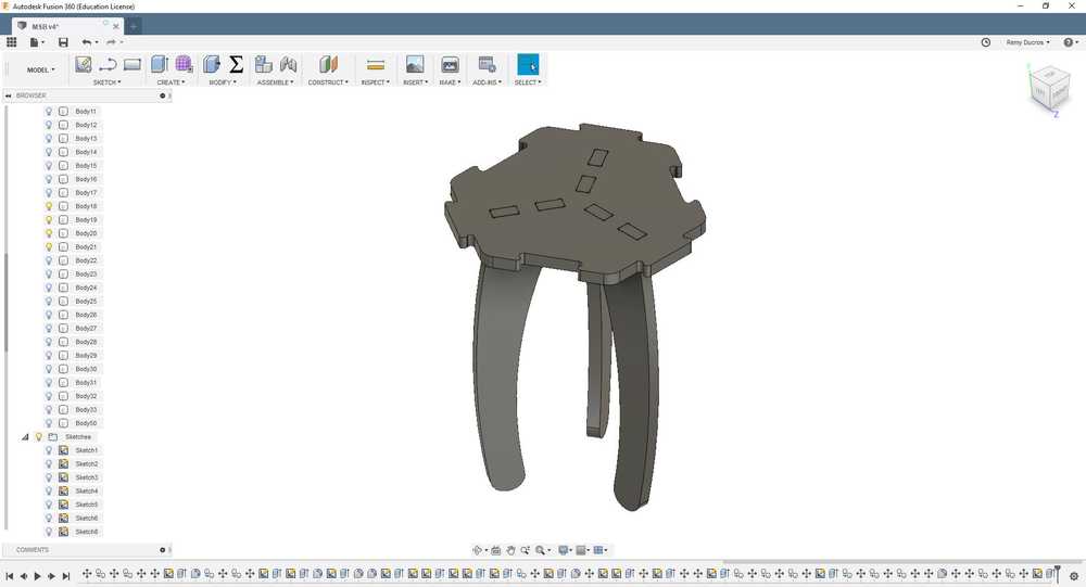
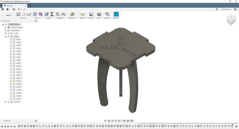
To improve the design, I made the legs closer to the center and all going to different direction. This way I may have stability in all direction. I also increased the offset of the outside of the plate to make the module easier to assemble.
Finally I made another shape of the same module to be more creative.
 |
 |
 |
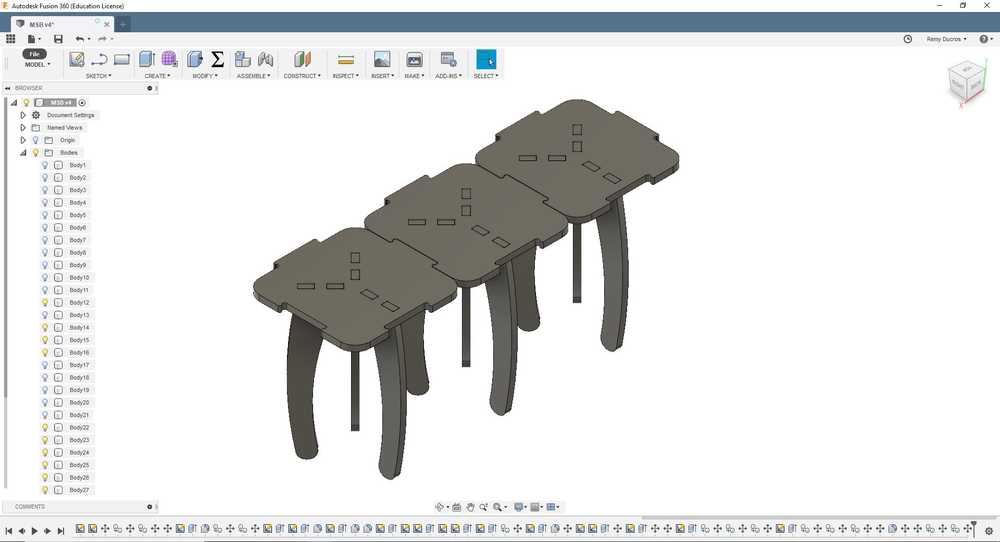
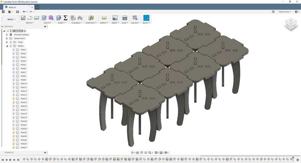
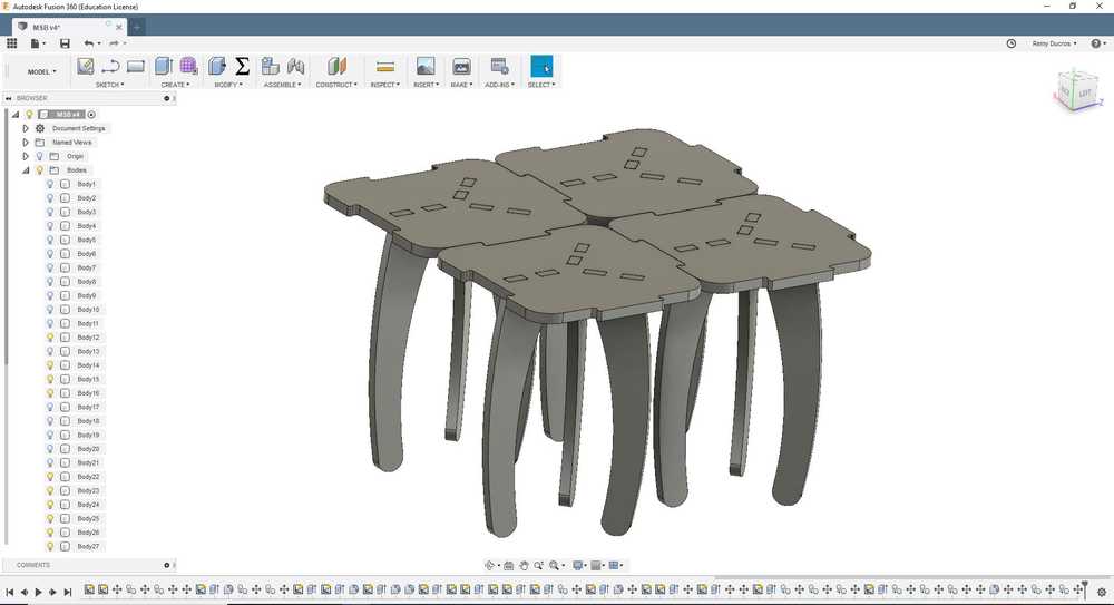
Possible assemblies
Here are some possible assemblies for this module :
 |
 |
 |
 |
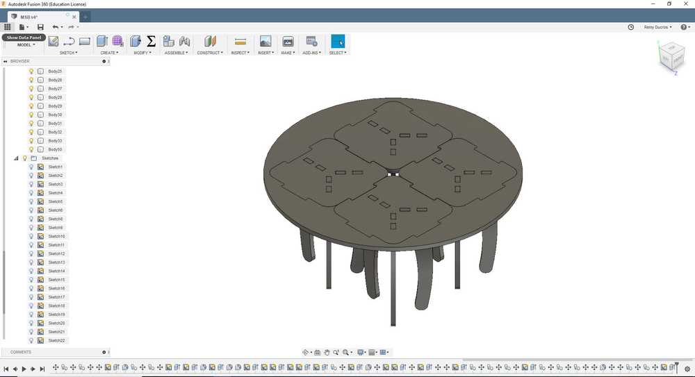 |
NOTE : We can remove some of the legs if needed for the bigger assemblies.

Ce(tte) œuvre est mise à disposition selon les termes de la Licence Creative Commons Attribution - Pas d’Utilisation Commerciale - Partage dans les Mêmes Conditions 4.0 International.