20. Project development
| Documentation | |
|---|---|
| 1. BoatduinoPackaging.stl | 2. SensorPackaging.stl |
| 3. DirectHighSpeedPropulsion.stl | 4. RemoteHighSpeedPropulsion.stl |
| 5. RemoteLowSpeedPropulsion.stl | 6. ElectronicPackaging.stl |
| 7. Skeleton.dxf | 8. WaterWings.dxf |
| 9. Cabin.dxf |
I’ll document here all the extra work I had to accomplish to make the boat work.
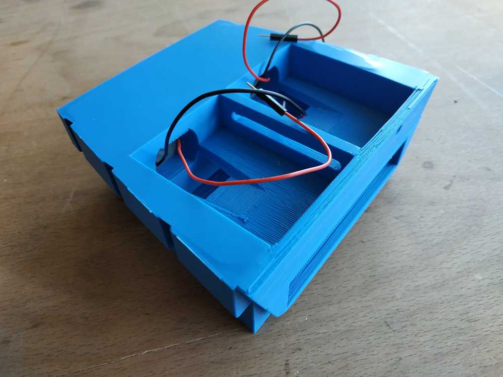
Integration of the battery
I made an housing for the battery and the motors. I left some room for the PCB and sensors. The module is 3D printed and fits in the skeleton (no glue needed).
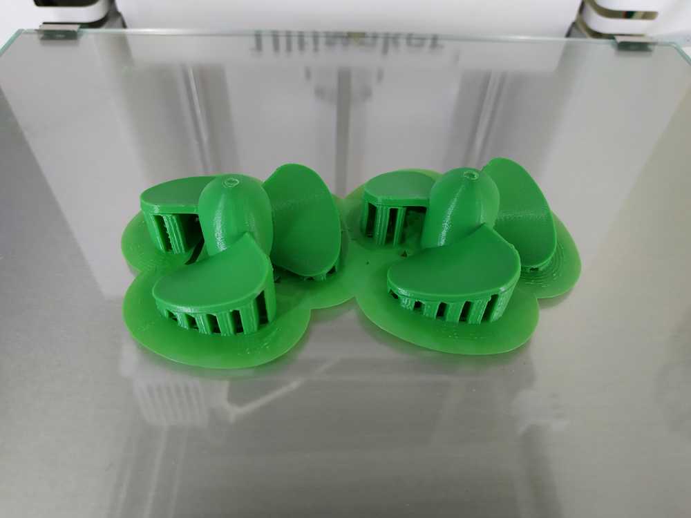
I used the following parameters for this print and all the others documented on this page :
- Material : PLA
- Infill : 10%
- Temperature : 205°C
- Bed Temperature : 60°C
- Brim : On
- Support : On
 |
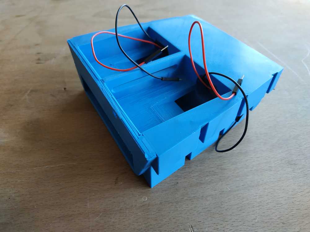 |
NOTE : I did this before properly thinking about my propulsion system. Finally I removed the motors to remote the propulsion system.
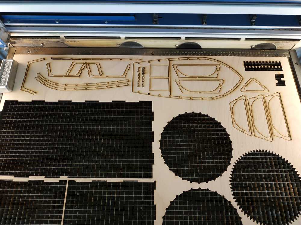
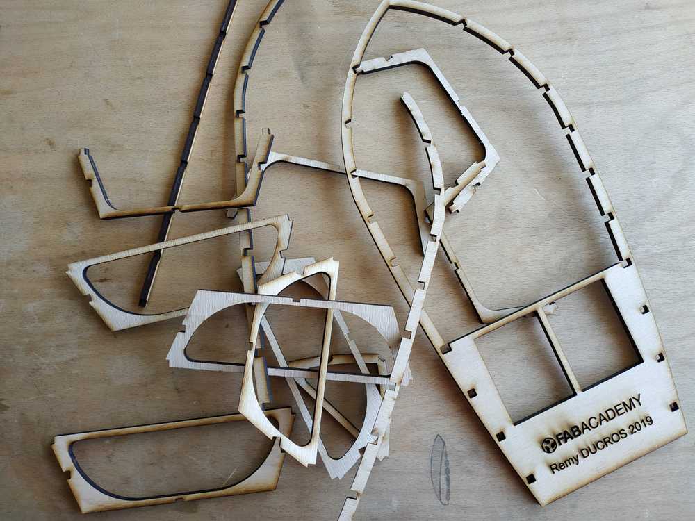
The skeleton
Throughout the time I changed my mind on what size my boat should be. I reduced the size by 50% so I had to make a new skeleton.
This time I used 5mm plywood sheet and cut it using the lasercutter and the following parameters :
- Speed : 5
- Power : 100
- Frequency : 50
- Type : CO2
- Passes : 1
 |
 |
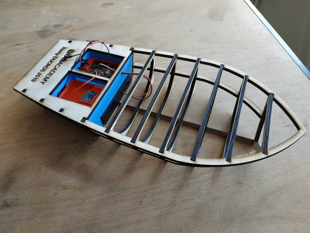
Everything fits as a presskit, no glue needed. I assembled it with the 3D printed part I previously made for the electronics and the battery.
 |
 |
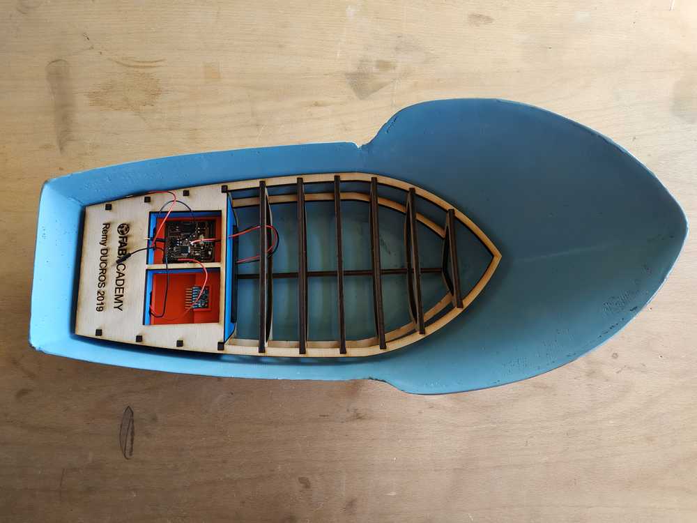
The whole thing fits well in the hull.
System integration
As I wanted my boat to be modular I thought of an integration where we can easily change :
- The propulsion system
- The sensor
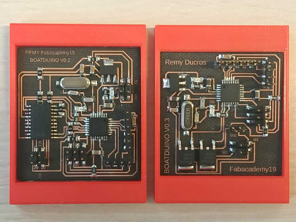
- The controller board
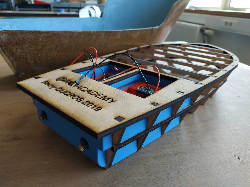
Modular electronic part
I left some room in the boat for small boxes to fit my boatduinos. I 3d printed them.
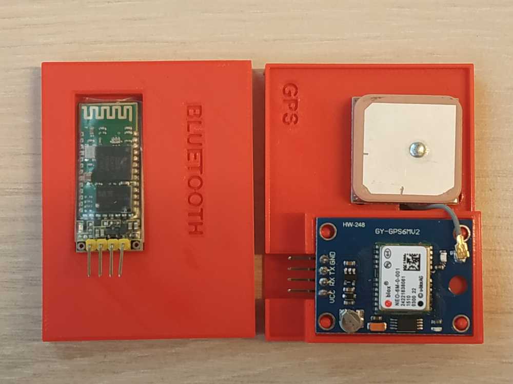
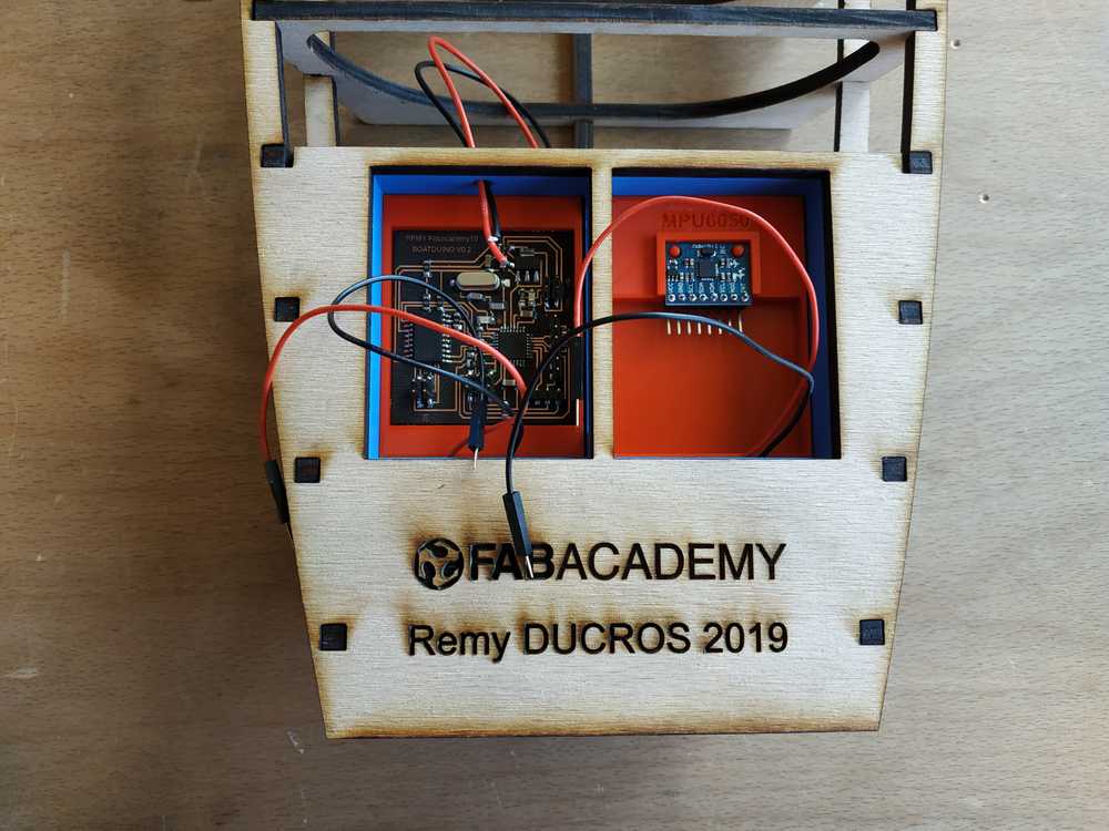
Sensor and PCB modules
I left some room in the boat to make some packaging around my electronics boards.
 |
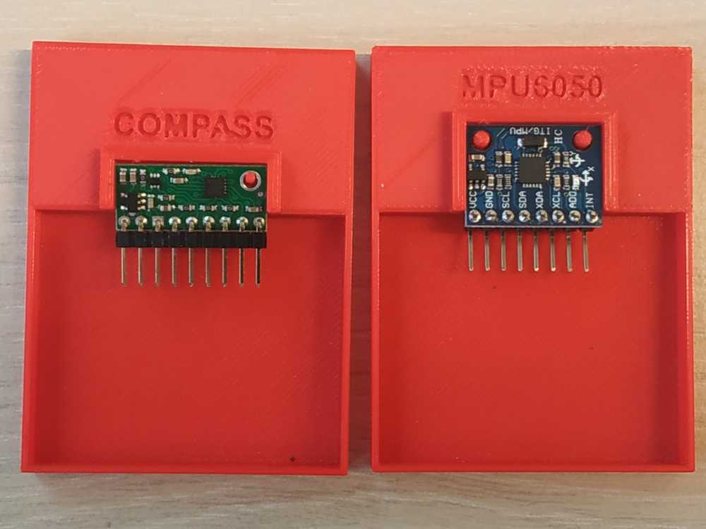 |
This way we can make the configuration we want to control the boat changing the boatduino version and the sensor we want to use.
 |
 |
Propulsion system
My wish is the boat to be modular so I’ve made three propulsion systems that we simply clip or remove from the boat (no glue or screws needed, it’s a snug fit).
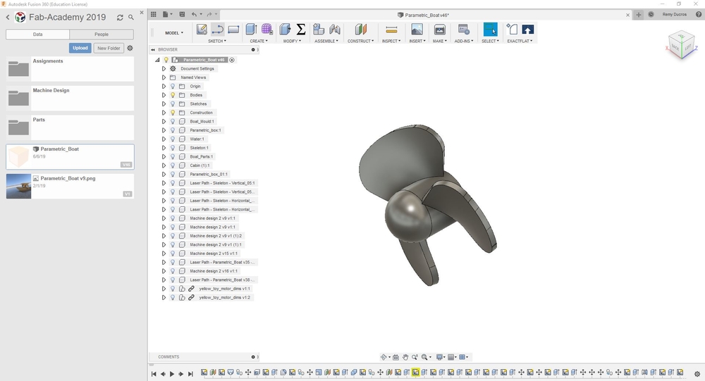
The propeller
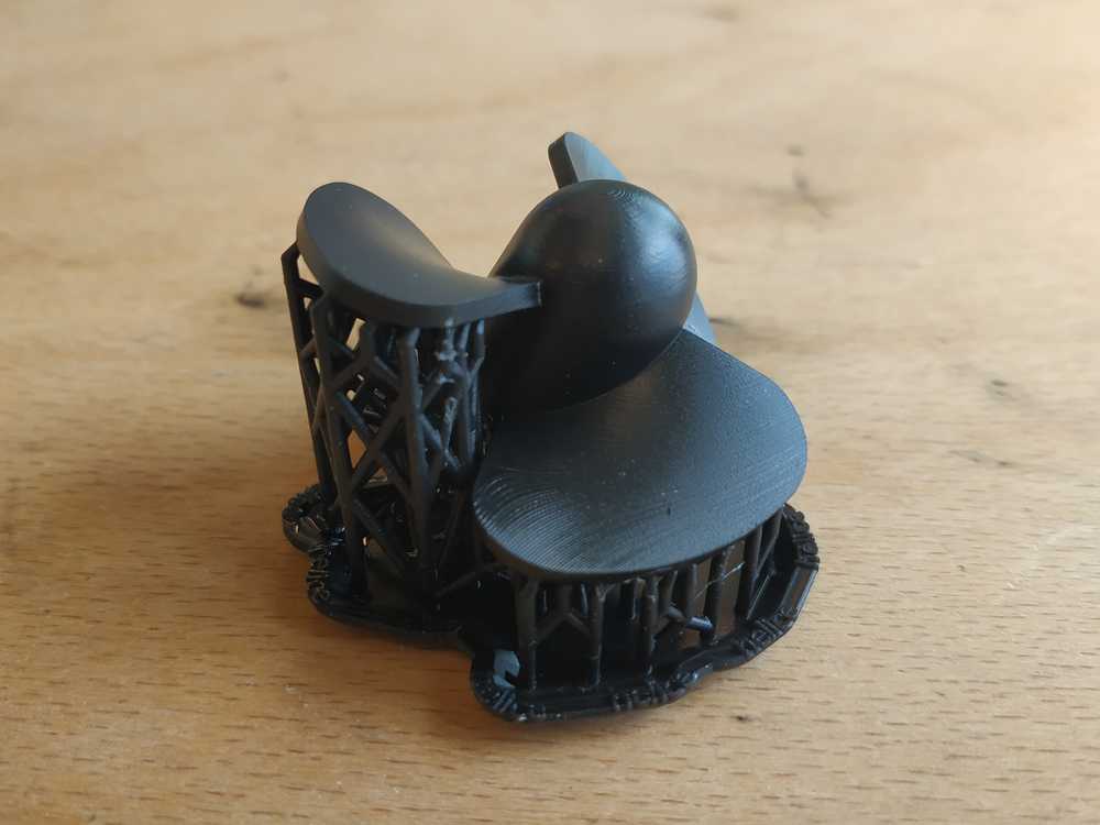
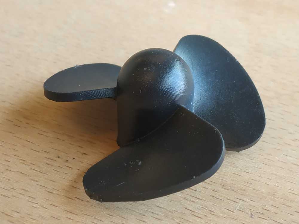
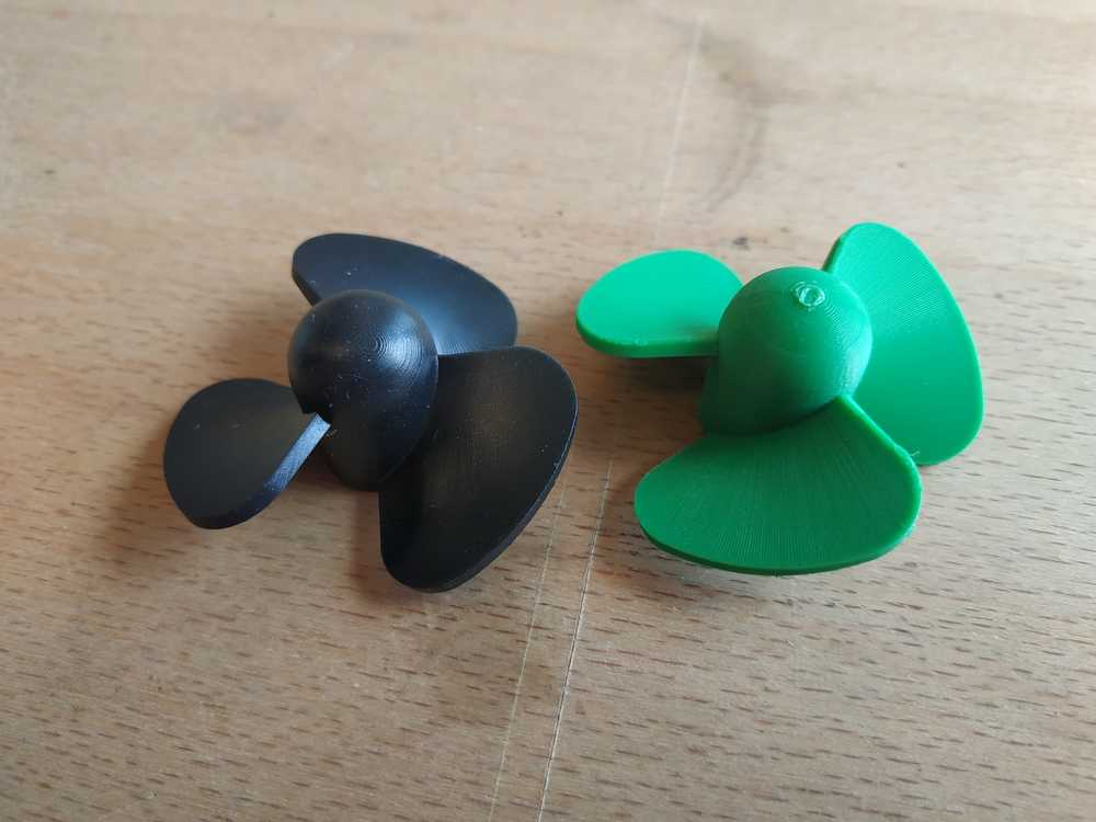
I made my own propellers based on this tutorial using fusion 360. I 3D printed those.
 |
 |
This design can be improved for better performances, yet it’s (I think) a descent design for my project.
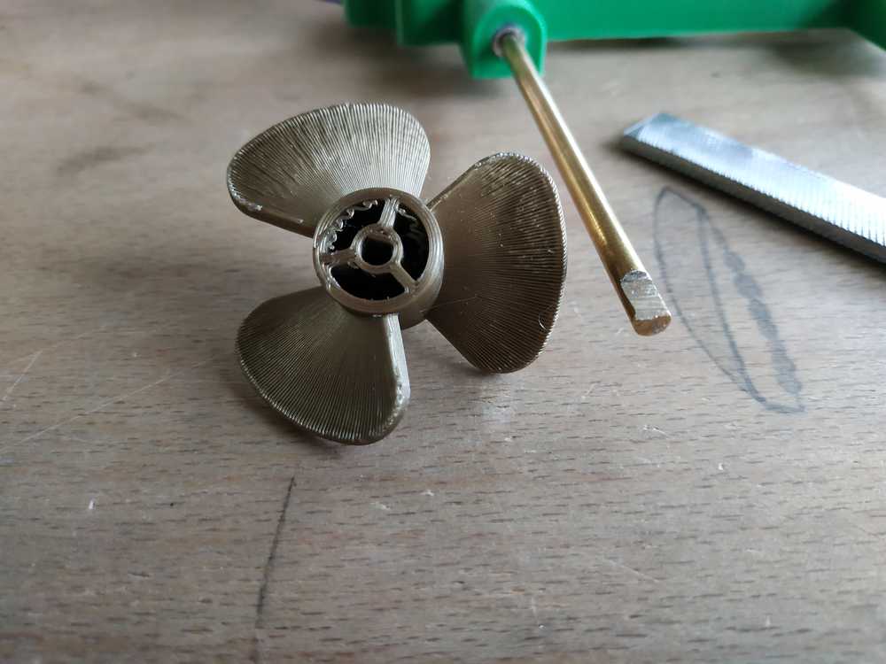
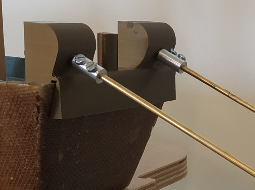
To mount it on my system I used a brass rod and filled it to have a snug fit with the propellers.
 |
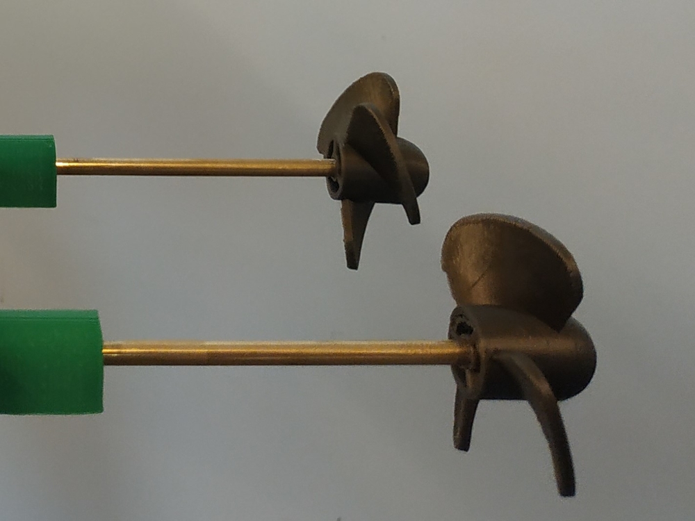 |
I decided to make a propeller using the SLA printer to have a better surface finishing and durability.
 |
 |
NOTE : I finally sticked to the models made using the FDM printer because it’s easier to fit it with the brass rod but for durability I may change the material I used (though PLA).
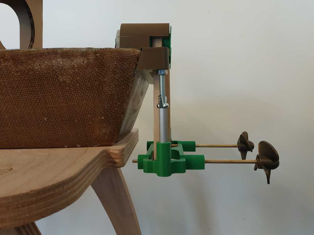
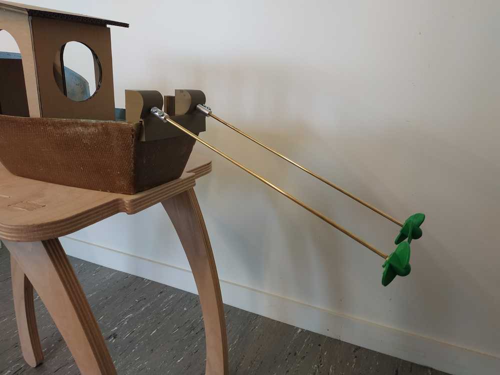
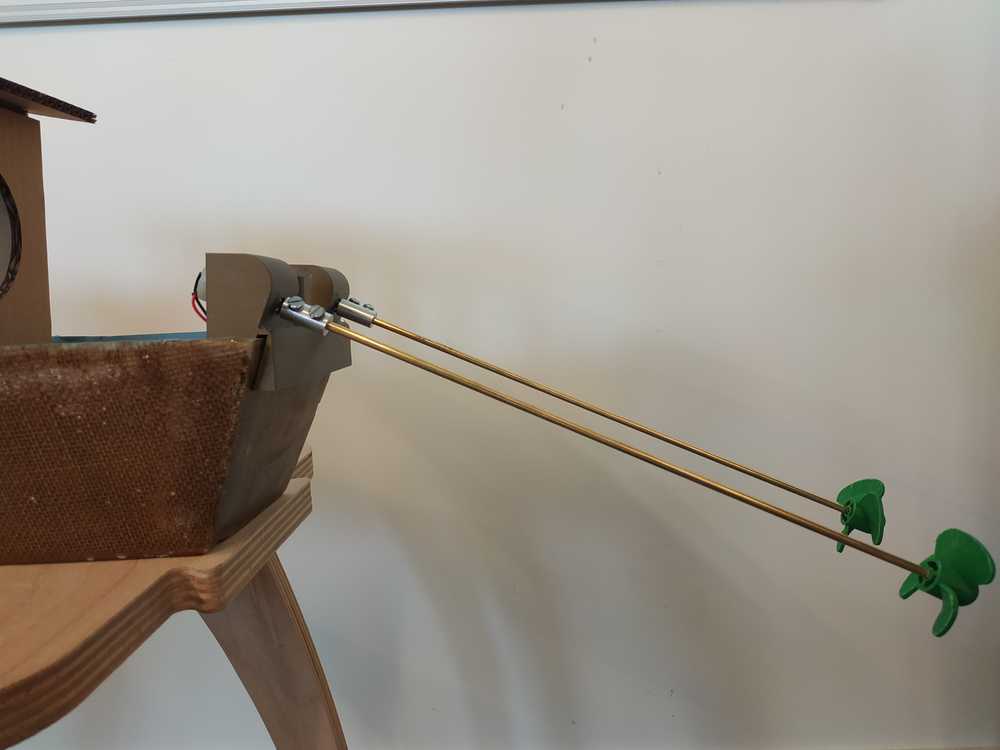
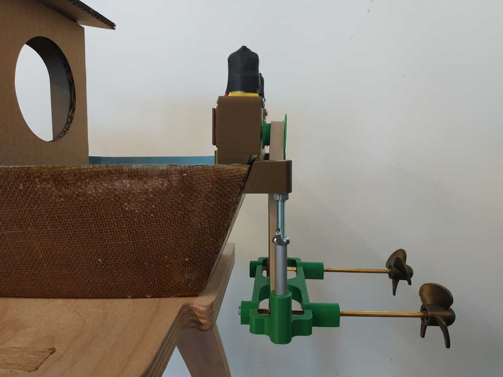
High Speed Remote Propulsion System
This first system is here to provide a remote propulsion to the boat.
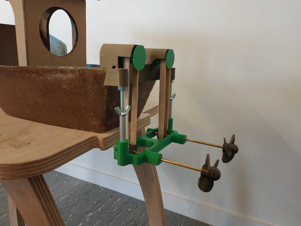
I 3D printed and assembled everything.
 |
 |
NOTE : I’ve used 10mm width rubber band as belts for this system. I can control the tension of the belts using the butterfly nuts. For the rotation of the propellers underwater I used aluminium tube to guide some brass rods. As the materials are very different there is low friction betweeen aluminium and brass.
I’ve plugged the system directly to the power supply to see the power consumption to make sure my PCB could handle it.
We can see that it’s working but sometimes a belt may go off. Also we can see that the power consumption is about 2.2A (and I don’t even have the force of the water on the propeller envolved). My battery can supply this much current but the H-bridge of the boatduino V0.2 cannot handle it.
To use this system, I need to design a boatduino V0.3 which can handle the high current consumption.
PRO’S :
- It’s going fast
- It looks good
CON’S :
- We loose precision in the controls
- The power consumption is high
- The belts may go off
EDIT : I’ve changed my gear design and I don’t have anymore belt issues.
NOTE : The speed creates vibrations that loosen the nuts. It’s important to tighten everything.
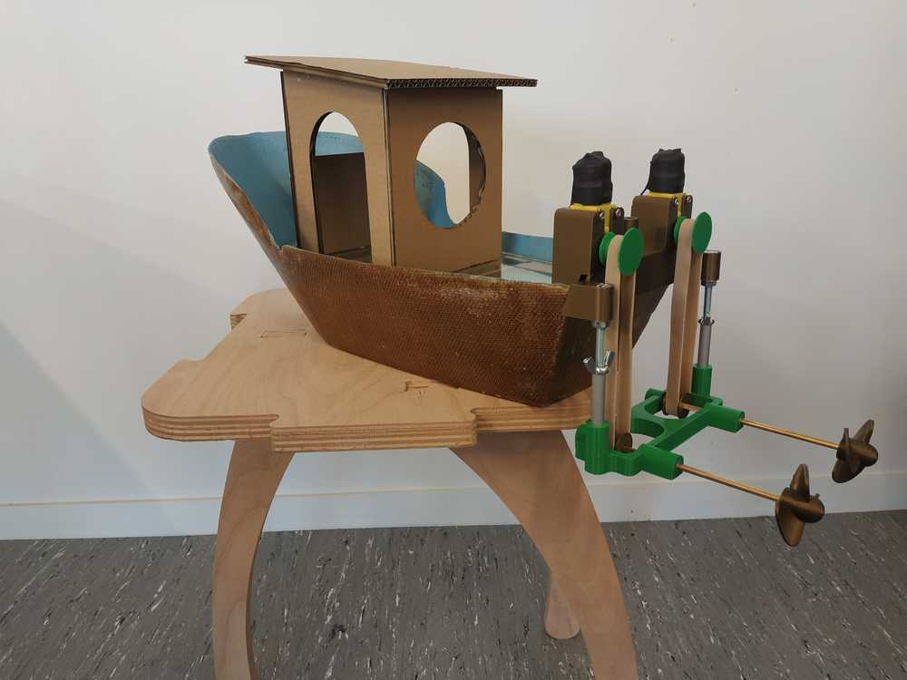
High Speed Propulsion System
This time I gave an angle to my motors so the shafts go directly in the water.
I 3D printed and assembled everything.
 |
 |
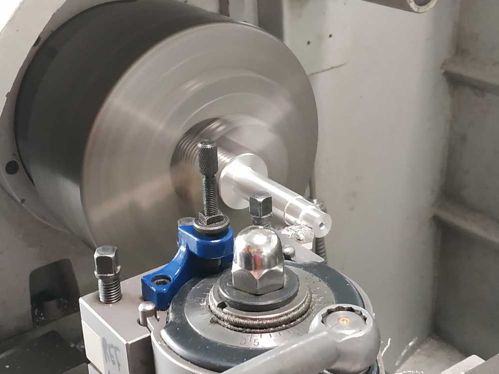
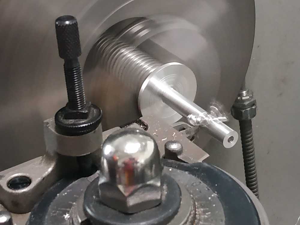
I used a lathe to make a connector between the motor and shaft. I made a technical drawing of the part :
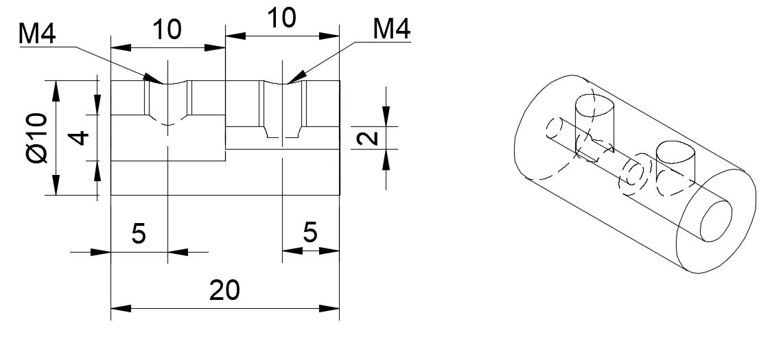
NOTE : I’m using mm.
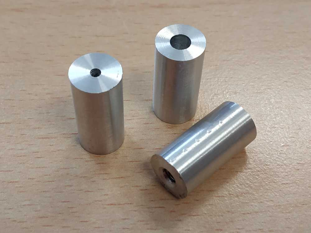
To make it I’ve been guided by Christ Noel a young student from the production school of Icam Paris. I used aluminium scrap from the workshop :
 |
 |
Here what it looks like completed :
 |
 |
I’ve plugged the system directly to the power supply to see the power consumption to make sure my PCB could handle it.
We can see that the system works. The power consumption is about 700 mA so it can be used with my boatduino V0.2. However even if we don’t have overhangs of the shafts, this system creates lots of vibrations which can be a problem.
PRO’S :
- It’s going fast
- No belt issue
- Simple design
CON’S :
- It looks bad
- We loose a bit of energy as the propller aren’t pushing backward
- It creates lots of vibrations
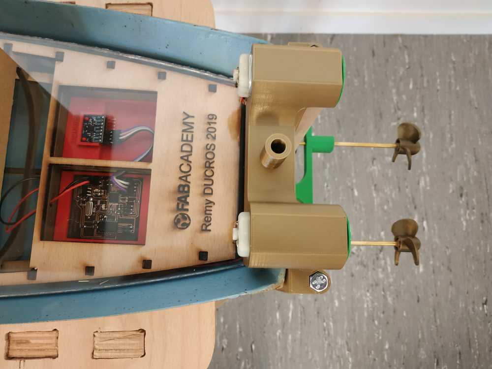
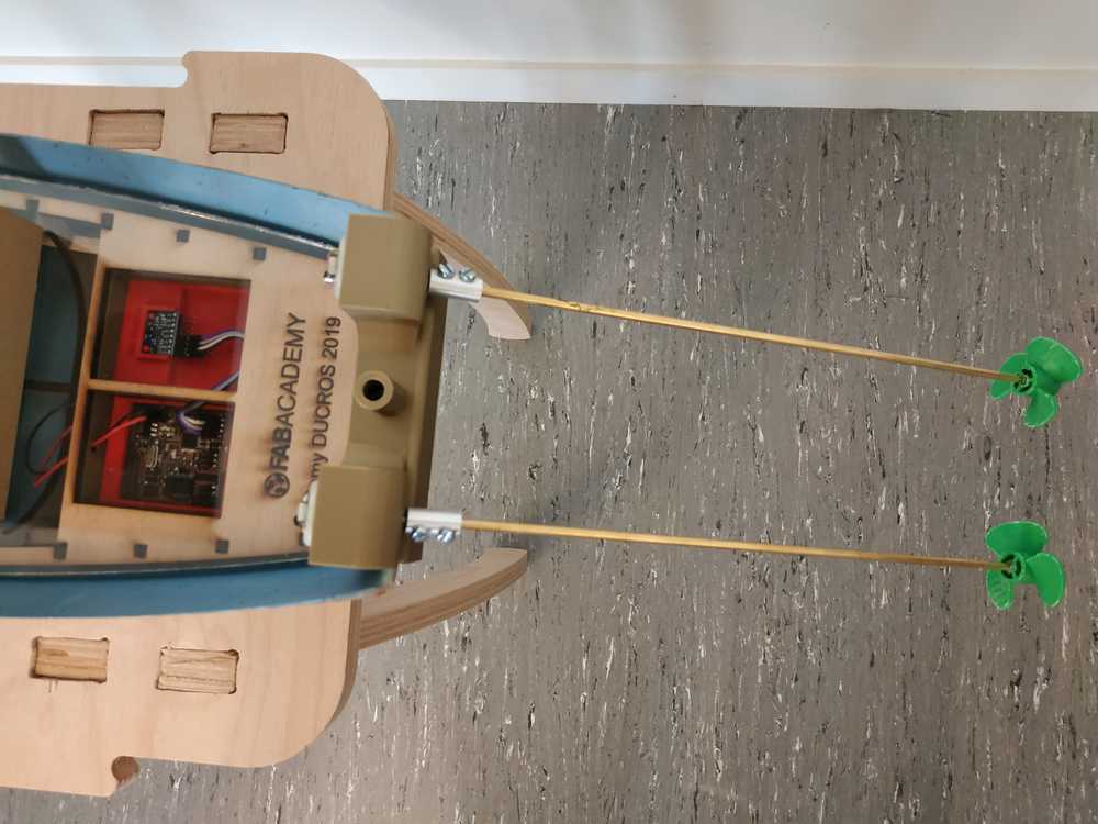
Low Speed Remote Propulsion System
Finally I modified my remote propulsion system to use motors with lower rotation speed but higher torque.
I 3D printed and assembled everything.
 |
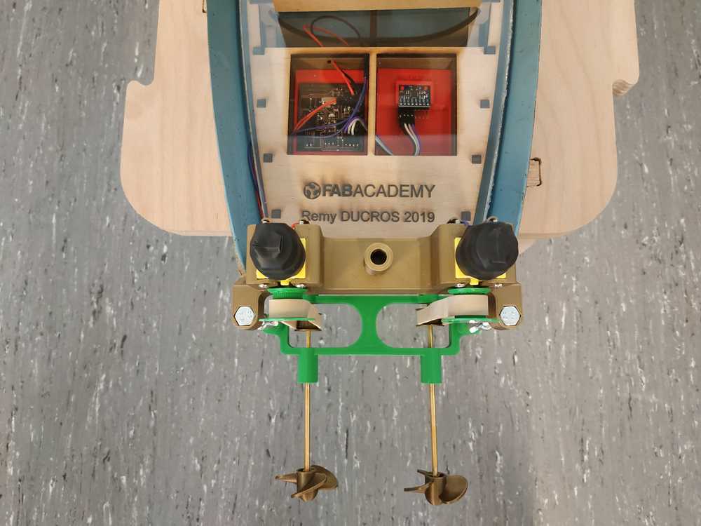 |
NOTE : I’ve just changed the motor packaging (compared to the first option proposed). The connections and underwater parts are the same.
I’ve plugged the system directly to the power supply to see the power consumption to make sure my PCB could handle it.
We can see that it’s working fine and with only a consumption of 0.2A per motor. My boatduino V0.2 can handle this configuration.
PRO’S :
- It looks good
- We have great controls on the boat
- The power consumption is lower than any other option
CON’S :
- The boat goes slow (like really slow)
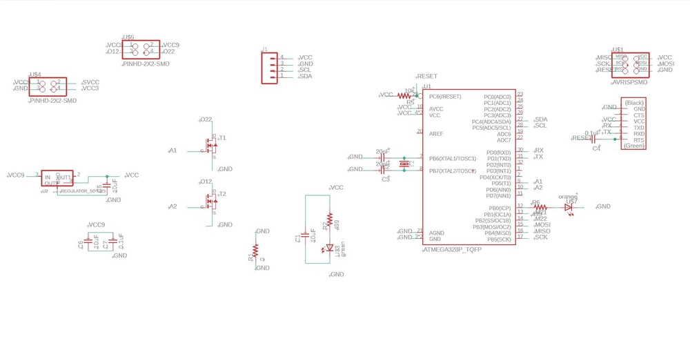
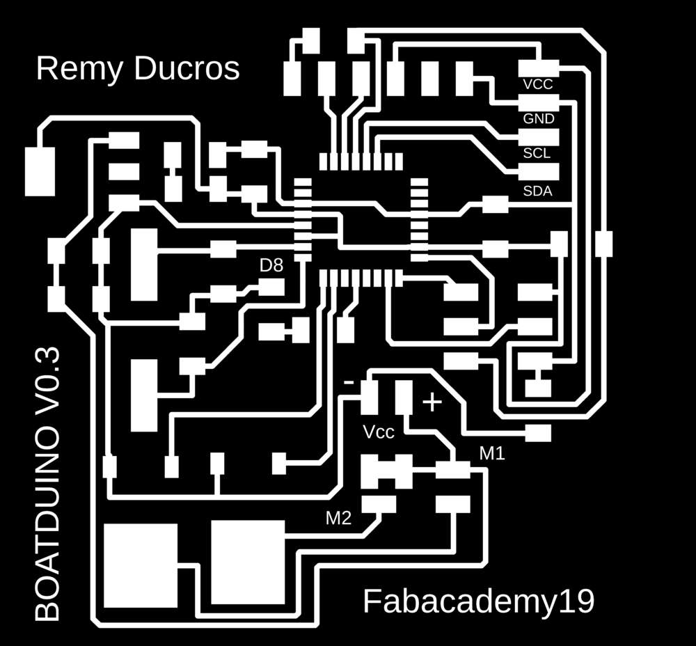
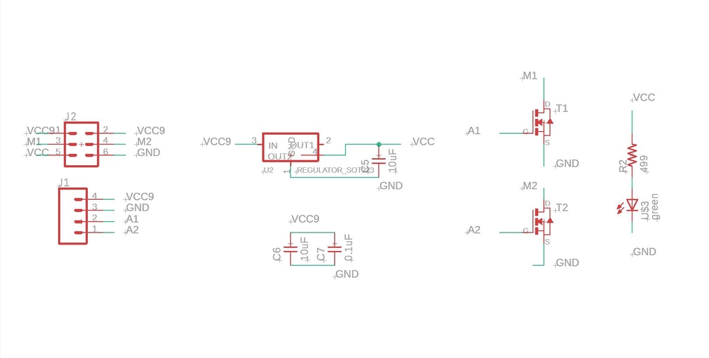
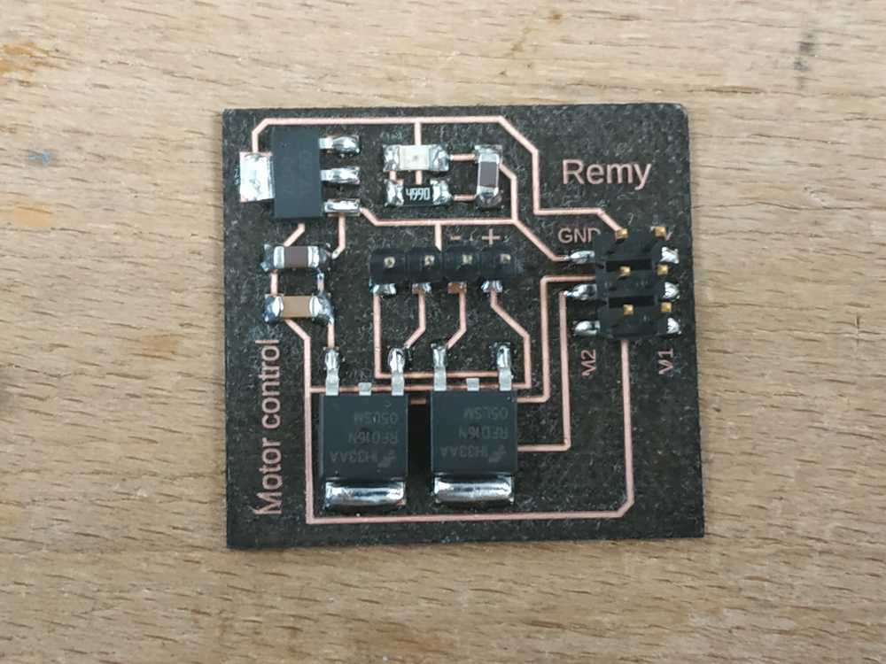
Boatduino V0.3
Making the boatduino V0.3
The Boatduino V0.3 is designed to control two DC motors but instead of using a H bridge, I’ll use two N-mosfets. The benefits from this modification is that I’ll be able to drive much more current to the motors. However, I won’t be able to change the motors direction and speed. I’ll just be able to independently switch on and off each motor.
 |
 |
Here’s what it looks like completed.
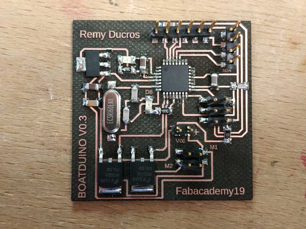
After bootloading the microcontroller I did my usual tests and it worked fine. I found out that I had to change my LDO as I somehow damaged the part (the output was only about 2.5V not 5V as expected).
Before trying my system with motors, I first plugged LEDs to make sure I could control the mosfets properly. I used this code to sequence my system :
// the setup function runs once when you press reset or power the board
void setup() {

  pinMode(6, OUTPUT);// motor 1
  pinMode(9, OUTPUT); //motor 2
  pinMode(8, OUTPUT); //embeded led
}

// the loop function runs over and over again forever
void loop() {
  digitalWrite(8, LOW);
  digitalWrite(6, HIGH);
  digitalWrite(9, LOW);
  delay(3000);

  digitalWrite(6, LOW);
  digitalWrite(9, HIGH) ;
  delay(3000);

  digitalWrite(6, HIGH);
  digitalWrite(9, HIGH);
  delay(3000);

  digitalWrite(6, LOW);
  digitalWrite(9, LOW);
  digitalWrite(8, HIGH);
  delay(3000);
}
Everything worked fine :
I replaced one LED with a motor and this time it didn’t work so well. Each time the motor started it stopped and it looked like the microcontroller was reseting:
NOTE : With the motors plugged we could never see the embedded LED switch on but when I unplugged it the sequence started again and everything worked fine.
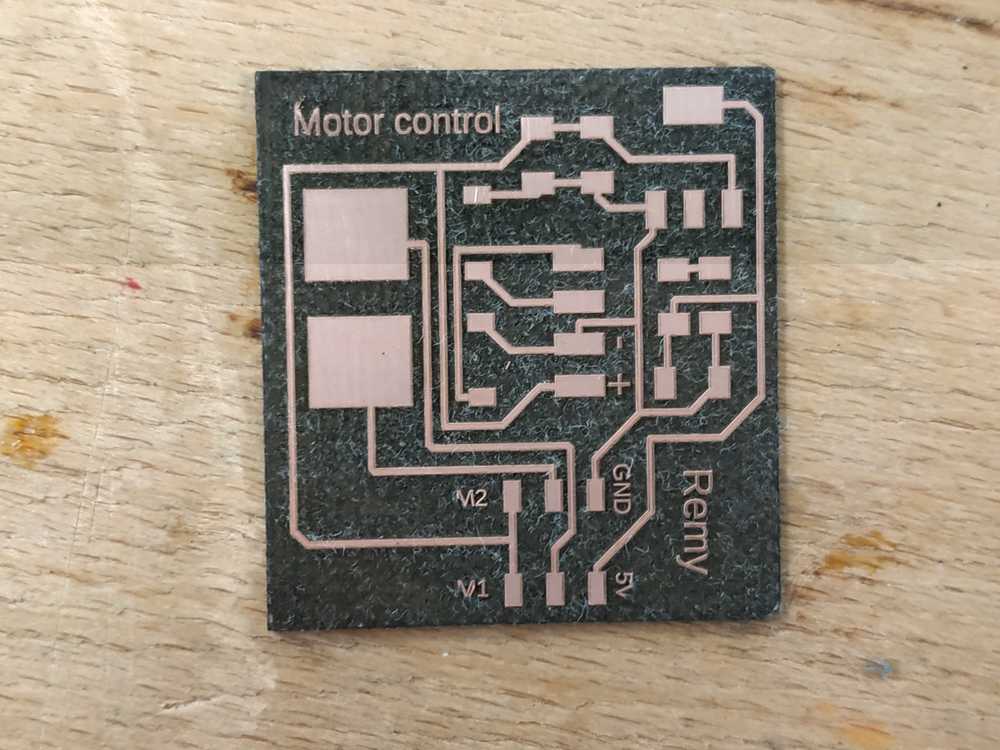
Making it work
As Neil suggested instead of having everything on the same PCB (which creates power issues as the mosfet swithes on and off) I’ve made a pcb for the mosfets and I’ll use my boatduino v0.1 to control this PCB. The benefit to remote the power supply from the command is that the wires will act like coils that will prevent the current interference to disturb the commmand signal.
 |
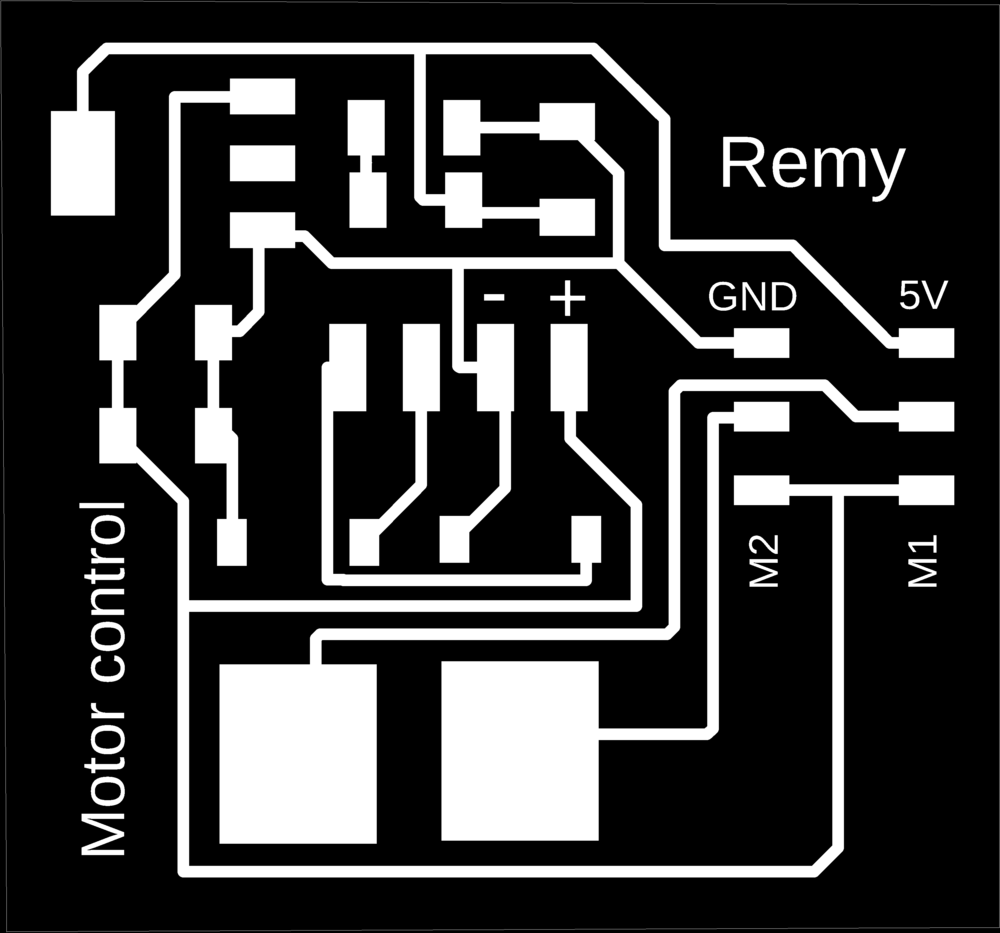 |
Here’s what it looks like completed.
 |
 |
I made a similar code to the previous one. I changed my pin numbers to use those available from my boatduino V0.1.
// the setup function runs once when you press reset or power the board
void setup() {

  pinMode(6, OUTPUT);
  pinMode(5, OUTPUT);
  pinMode(8, OUTPUT);

}

// the loop function runs over and over again forever
void loop() {
  digitalWrite(8, LOW);
  digitalWrite(6, HIGH);
  digitalWrite(5, LOW);

  delay(3000);

  digitalWrite(6, LOW);
  digitalWrite(5, HIGH) ;
  delay(3000);

  digitalWrite(6, HIGH);
  digitalWrite(5, HIGH);
  delay(3000);

  digitalWrite(6, LOW);
  digitalWrite(5, LOW);
  digitalWrite(8, HIGH);
    delay(3000);
}
This time it worked well :
This is the setup I need to use if I want to have the maximum of current going through my motors.
Water wings
To avoid my boat from flipping around I’ve decided to make water wings on each side of the hull.
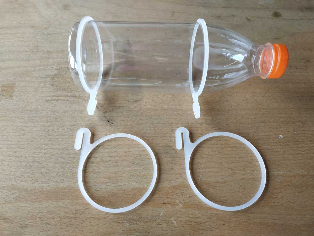
I’ve recycled two plastic bottles and I lasercut in acryclic parts to fit the bottle and make it stay on the side of the boat.
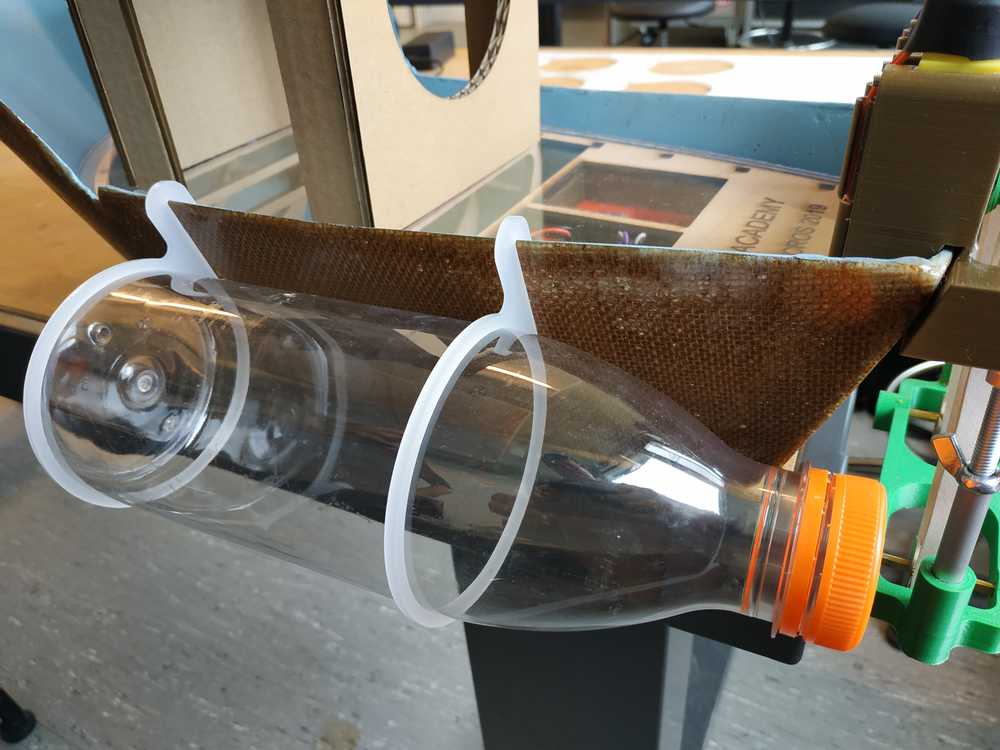
Once again it’s modular, and we don’t need glue or screws to fix it.
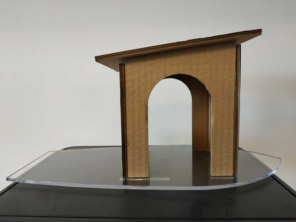
The cabin
This final step is to make the boat looks like a boat (as per my design). We can however find two purposes of the cabin :
- The top of the cabin can carry a solar pannel
- The floor can protect the electronics from the environment
I’ve decided to make the cabin using cardboard as I don’t want to add weight on the top of the boat to prevent it from flipping around (and also because cardboard is a great material). I’ve decided to make the floor using 5mm acrylic sheet so we can see what’s below the floor.
 |
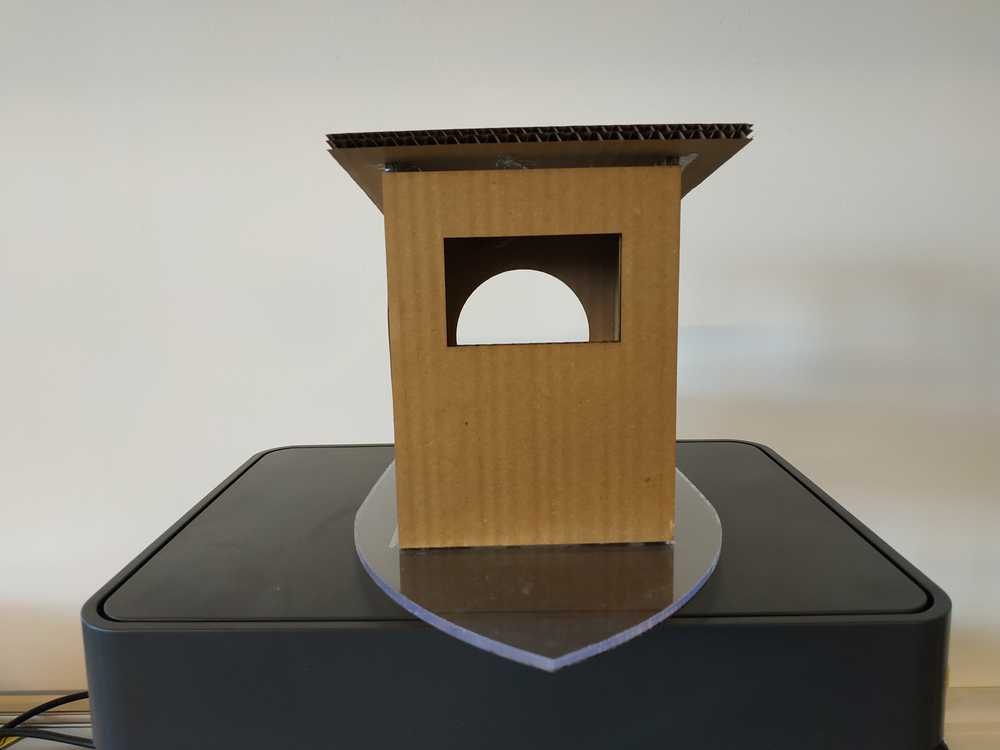 |
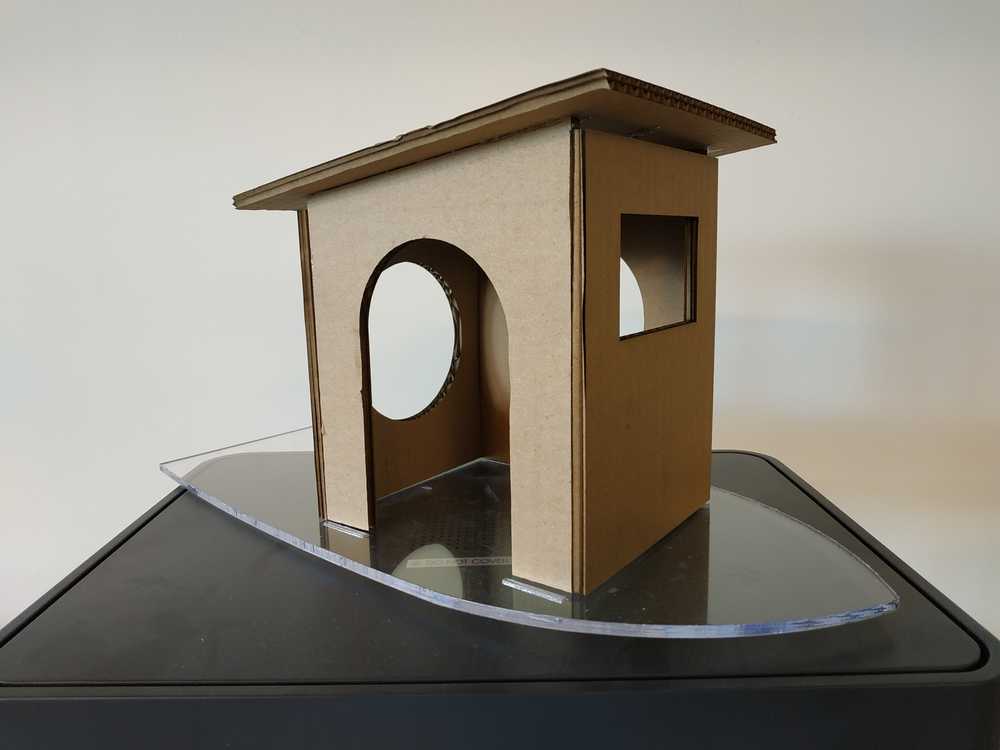
As per my previous experimentation, a press fit works fine with cardboard but it’s not working so well when we want to make a “box shape” with it. Here to assemble everything, I used hot gun glue to seal everything together.
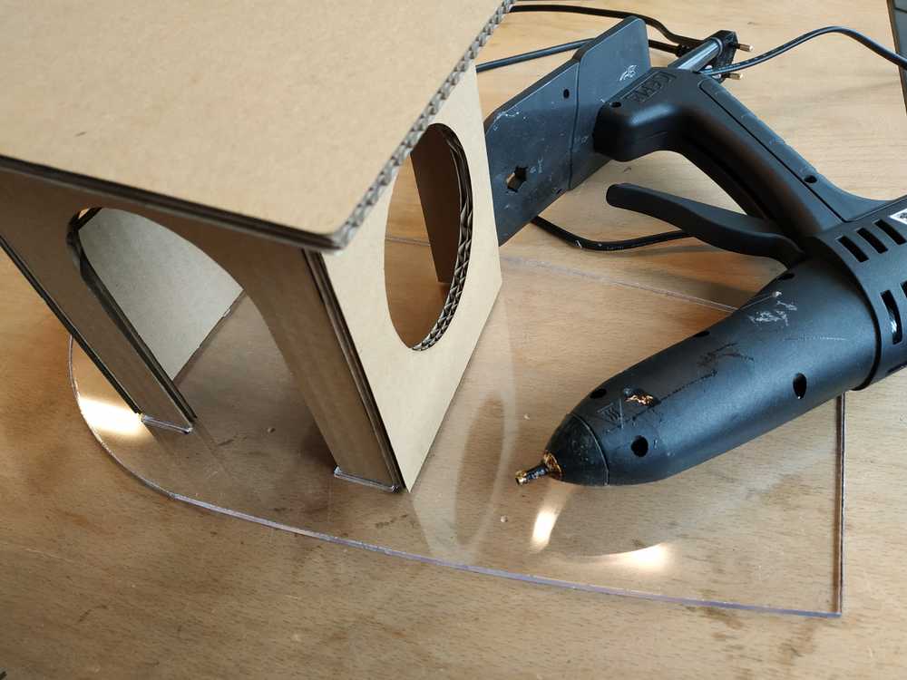
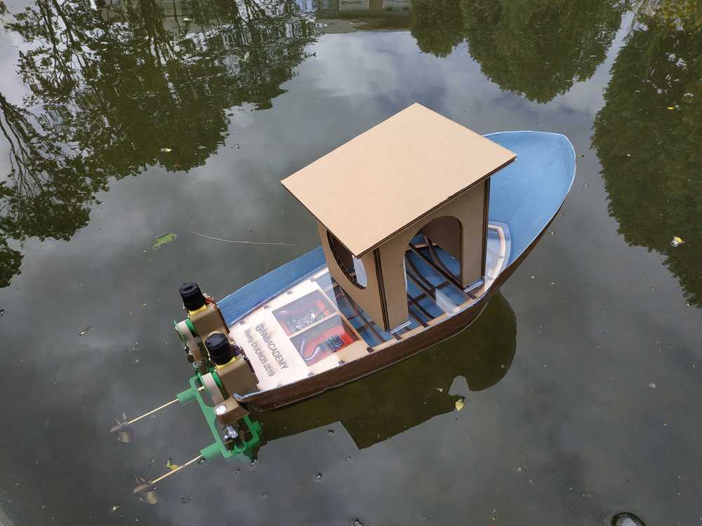
I’m pleased with the result.
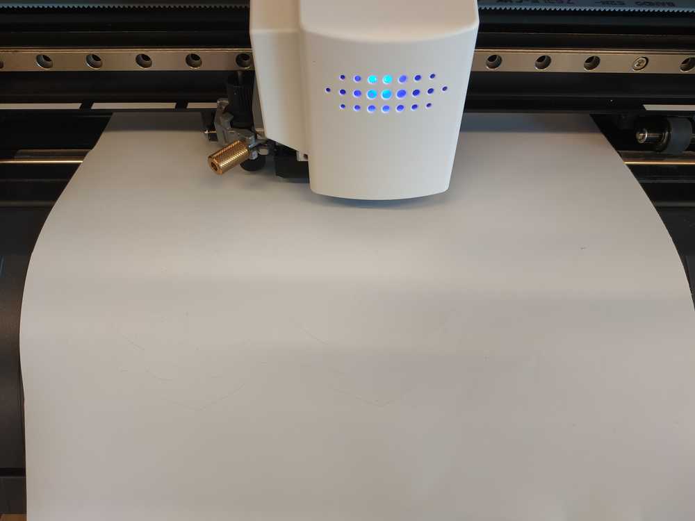
Decoration
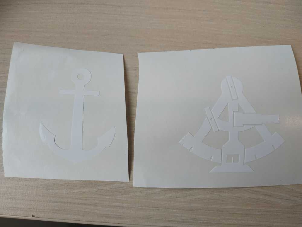
Finally I used the vinyl cutter to do a bit of decoration.
I’ve used white vinyl to cut an anchor and a sextan that I put on the side of my boat.
 |
 |
I placed each sticker on the side of the boat :
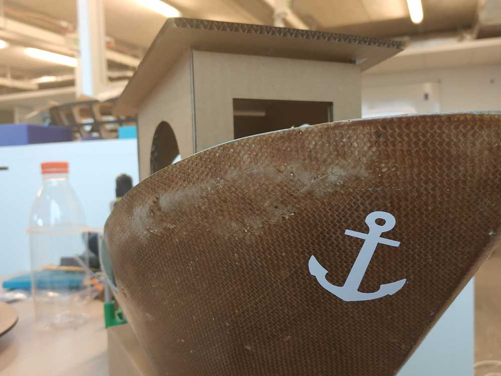 |
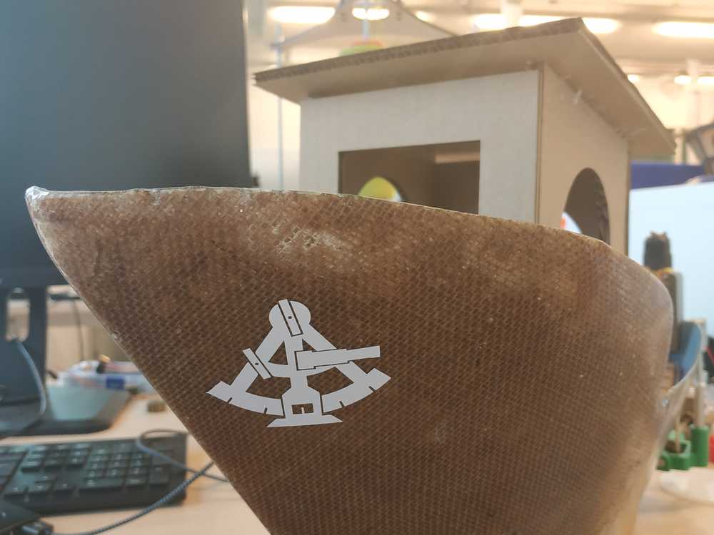 |
I also gave my boat a name and I made a sticker I put on the back of my boat :
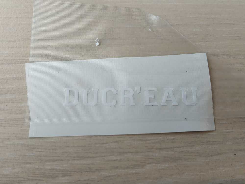 |
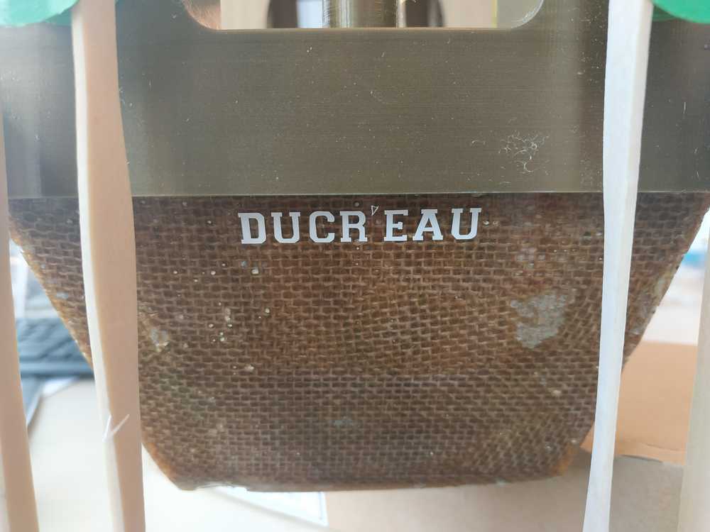 |
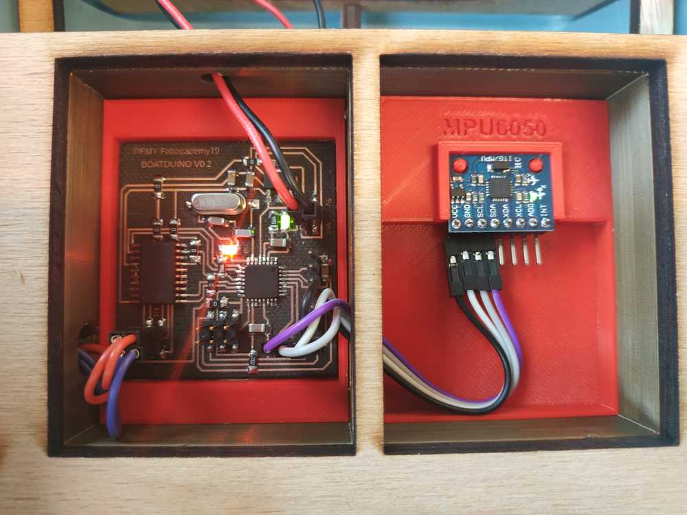
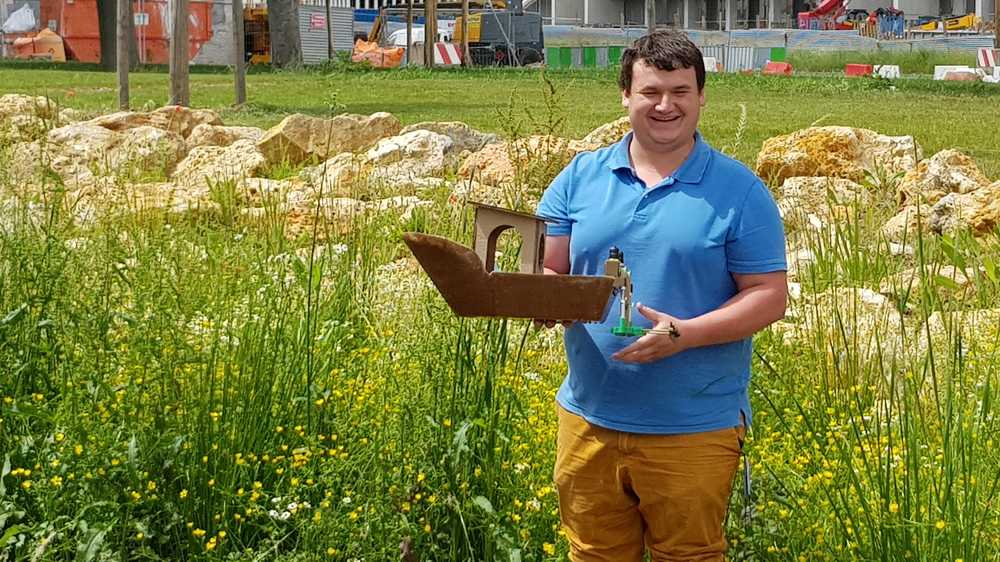
First test on water
After making everything to make it work I decided to do a test on water.
I used the following configuration :
- Boatduino V0.2
- MPU6050
- Low Speed Remote Propulsion System
I’ve made a code to simply switch on and off each motor depending on the yaw angle of the boat. This code can be used with the mosfet PCB as well.
#include <Wire.h>
#include <MPU6050.h>

MPU6050 mpu;

//Initialize Motor 1
const int controlPin1 = 5; // connected to the H-bridge
const int controlPin2 = 12; // connected the H-bridge
const int enablePin = 6;   // connected to the H-bridge
int motorEnabled = 0; // Turns the motor on/off
int motorSpeed = 0; // speed of the motor

//Initialize Motor 2
const int controlPin3 = 9; // connected to pin 7 on the H-bridge
const int controlPin4 = 11; // connected to pin 2 on the H-bridge
const int enablePin2 = 10;   // connected to pin 1 on the H-bridge
int motor2Enabled = 0; // Turns the motor on/off
int motor2Speed = 0; // speed of the motor

// Timers
unsigned long timer = 0;
float timeStep = 0.01;

// Yaw values
float yaw = 0;

void setup()
{
  Serial.begin(115200);

    // initialize the inputs and outputs
  pinMode(controlPin1, OUTPUT);
  pinMode(controlPin2, OUTPUT);
  pinMode(controlPin3, OUTPUT);
  pinMode(controlPin4, OUTPUT);
  pinMode(enablePin, OUTPUT);
  pinMode(enablePin2, OUTPUT);
  pinMode(8, OUTPUT);

  // pull the enable pin LOW to start
  digitalWrite(enablePin, LOW);
  digitalWrite(enablePin2, LOW);


  // Initialize MPU6050
  while(!mpu.begin(MPU6050_SCALE_2000DPS, MPU6050_RANGE_2G))
  {
    Serial.println("Could not find a valid MPU6050 sensor, check wiring!");
    delay(500);
  }

  // Calibrate gyroscope. The calibration must be at rest.
  // If you don't want calibrate, comment this line.
  mpu.calibrateGyro();

}

void loop()
{
  timer = millis();

  // Read normalized values
  Vector norm = mpu.readNormalizeGyro();

  // Calculate Yaw
  yaw = yaw + norm.ZAxis * timeStep;

  // Output
  Serial.print(" Yaw = ");
  Serial.println(yaw);

  // Wait to full timeStep period
  delay((timeStep*1000) - (millis() - timer));

  if (yaw >= -30 && yaw < 30) {
    digitalWrite(8, HIGH);

  // Turn on motor1
    digitalWrite(controlPin1, HIGH);
    digitalWrite(controlPin2, LOW);

  // Turn on motor2
    digitalWrite(controlPin3, HIGH);
    digitalWrite(controlPin4, LOW);

    // PWM the enable pin to vary the speed of both motors
    analogWrite(enablePin, 255);
    analogWrite(enablePin2, 255);
  }
else if (yaw > 30){
      digitalWrite(8, LOW);

  // Turn on motor1
    digitalWrite(controlPin1, HIGH);
    digitalWrite(controlPin2, LOW);

  // Turn on motor2
    digitalWrite(controlPin3, HIGH);
    digitalWrite(controlPin4, LOW);

    // PWM the enable pin to vary the speed of both motors
    analogWrite(enablePin, 255);
    analogWrite(enablePin2, 0);
  }
  else if (yaw < - 30){
      digitalWrite(8, LOW);

  // Turn on motor1
    digitalWrite(controlPin1, HIGH);
    digitalWrite(controlPin2, LOW);

  // Turn on motor2
    digitalWrite(controlPin3, HIGH);
    digitalWrite(controlPin4, LOW);

    // PWM the enable pin to vary the speed of both motors
    analogWrite(enablePin, 0);
    analogWrite(enablePin2, 255);
}
delay(10);
}
I assembled everything and tested the code.
Then I went to a pond to finally try my system. It was very windy and slitghly raining. I didn’t use the water wings as I could see my boat, with the weights of the battery was well balanced.
Here’s the video of the first try.
This first test was a good learning experience.
PRO’S :
- It works !
- The system is powerful enough to move the boat
- The boat didn’t flip around even with the wind
CON’S :
- I have a bad contact with one of my motor
- The boat will change direction with the wind
Anyways I was happy that I didn’t loose everything with this first test.
Second test on water
I fixed my wiring issue and started over my test.
This time it worked well. It was going straight and I’m now confident about putting the boat on water, I know it won’t flip around with this configuration.
During the first test, I could see that with only one motor on, the boat wasn’t turning much as expected. Instead of making a motor stop while the other one goes full speed I tested to reverse the direction of one motor to see if this time the boat would turn.
We can see on the video that it’s working even if it’s going slow. I need to do this modification to let the boat correct its direction.
Control the boat via bluetooth
To go further based on what I have done during the networking and communication week, and my previous tests, I made a code to remotely control the boat.
int val;

const int controlPin1 = 5; // connected to pin 7 on the H-bridge
const int controlPin2 = 12; // connected to pin 2 on the H-bridge
const int enablePin = 6;   // connected to pin 1 on the H-bridge
int motorEnabled = 0; // Turns the motor on/off
int motorSpeed = 0; // speed of the motor

const int controlPin3 = 9; // connected to pin 7 on the H-bridge
const int controlPin4 = 11; // connected to pin 2 on the H-bridge
const int enablePin2 = 10;   // connected to pin 1 on the H-bridge
int motor2Enabled = 0; // Turns the motor on/off
int motor2Speed = 0; // speed of the motor

void setup()
{
Serial.begin(9600);

  pinMode(controlPin1, OUTPUT);
  pinMode(controlPin2, OUTPUT);
  pinMode(controlPin3, OUTPUT);
  pinMode(controlPin4, OUTPUT);
  pinMode(enablePin, OUTPUT);
  pinMode(enablePin2, OUTPUT);

  // pull the enable pin LOW to start
  digitalWrite(enablePin, LOW);
  digitalWrite(enablePin2, LOW);

}

void loop()
{ val= Serial.read();

if(val=='a'){ //Go straight
    digitalWrite(controlPin1, HIGH);
    digitalWrite(controlPin2, LOW);
    digitalWrite(controlPin3, HIGH);
    digitalWrite(controlPin4, LOW);
    analogWrite(enablePin, 255);
    analogWrite(enablePin2, 255);
}

if(val=='b'){ //Go backwards
    digitalWrite(controlPin1, LOW);
    digitalWrite(controlPin2, HIGH);
    digitalWrite(controlPin3, LOW);
    digitalWrite(controlPin4, HIGH);
    analogWrite(enablePin, 255);
    analogWrite(enablePin2, 255);
}

if(val=='c'){ //Turn Right
    digitalWrite(controlPin1, HIGH);
    digitalWrite(controlPin2, LOW);
    digitalWrite(controlPin3, LOW);
    digitalWrite(controlPin4, HIGH);
    analogWrite(enablePin, 255);
    analogWrite(enablePin2, 255);
}

if(val=='d'){ //Turn Left
    digitalWrite(controlPin1, LOW);
    digitalWrite(controlPin2, HIGH);
    digitalWrite(controlPin3, HIGH);
    digitalWrite(controlPin4, LOW);
    analogWrite(enablePin, 255);
    analogWrite(enablePin2, 255);
}

if(val=='e'){ //Do a U turn
    digitalWrite(controlPin1, HIGH);
    digitalWrite(controlPin2, LOW);
    digitalWrite(controlPin3, LOW);
    digitalWrite(controlPin4, HIGH);
    analogWrite(enablePin, 255);
    analogWrite(enablePin2, 255);
}

if(val=='f'){ //STOP
    digitalWrite(controlPin1, LOW);
    digitalWrite(controlPin2, LOW);
    digitalWrite(controlPin3, LOW);
    digitalWrite(controlPin4, LOW);
}
delay(100);

}
I tested it first :
Then tried it on water :
Few lessons learnt during the test :
- I was able to control the direction of the boat via bluetooth (go straight, turn, slow down …)
- As soon there’s wind the boat as a tendancy to follow the wind making the controls much less efficient
Overall, I’ve tested different configurations of the boat and I was able to make them work. Work can be done to improve the overall system but I’m happy with what I’ve done.

Ce(tte) œuvre est mise à disposition selon les termes de la Licence Creative Commons Attribution - Pas d’Utilisation Commerciale - Partage dans les Mêmes Conditions 4.0 International.