12. Output devices
Group assignment
Measure the power consumption of an output device
Individual assignment
Add an output device to a microcontroller board you’ve designed, and program it to do something
| Documentation | |
|---|---|
| 1. MotorPCBAT44A.png | 2. MotorPCBAT44AEagleFiles |
| 3. HBridgePCBEagleFile | 4. BoatduinoV0.2EagleFiles |
This week, I’m going to make my own PCB to control a DC motor using a mosfet.

Measuring the power consumption of the DC motor
To read the power consumption of the motor I wanted to use, I’ve used two methods :
- I plugged directly the motor to a DC power supply and the supply gave me the current consumption
- I plugged an ammeter in series between my motor and the ground and read the value out of it
 |
 |
Here both results gave me the same result. For a power supply of 9V my motor is consuming around 100 mA. Given the formula P=V*I, the motor uses 0.9W. It’s not so much but it’s definitely enough to dammage the micocontroller if I use it to supply directly the motor.
I’ll use an external power supply to power the motor.
Controlling a motor
Component selection
To control the motor and start it when I want I’ll use a Mosfet. This transistor will allow an external power supply to go through the motor while the gate of the component get a voltage. Here with the help of the ATtiny44a I’ll use a pin that I’ll program to turn on and off. As I turn it on, I’ll supply 5V to the Mosfet gate which will allow the 9V to supply the motor. If I connect the pin to the ground, it will not supply the Mosfet gate so it will switch off the motor.
I’ve used a RFD16N05L MOSFET and I’ve been through its datasheet. From the datasheet I’ve seen that the component can handle 50V and 16A which is more than enough as I’m using, 9V and 0.1A. I also check the pinout to plug it correctly.
 |
 |
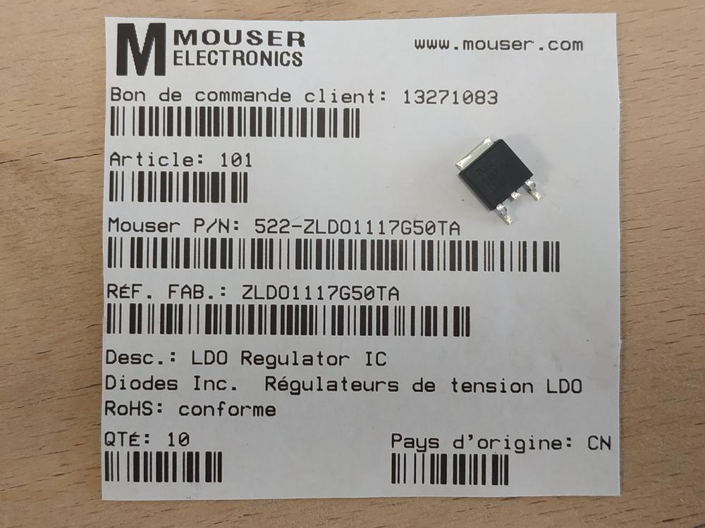
To supply my board, I used a 9V DC power supply. To give 9V directly to the microcontroller would damage it so I needed to regulate the voltage down to 5V. I’ve used a 5V regulator, the NCP1117 and I’ve bben through its datasheet. Here again I’ve learn few important things about the component. It gives a 5V output for inputs upto 20V. I’ve been through the pinout and check the recommended diagrams to make it work. As recommended I put a capacitor of 10uF between the output and the ground to have a proper regulation.
 |
 |
Making the board
I assembled all the components in a board with an ATtiny44 on EAGLE.
 |
 |
NOTE : As usual I put an LED to check if the board is correctly supplied and a diode around the motor to protect the Mosfet as it disconnected.
Then I made the PCB using the lasercutter and I solderred the components.
 |
 |
Programming the board
I made a very simple program to swith on and off the motor every second.
// the setup function runs once when you press reset or power the board
void setup() {
  // initialize digital pin 8 (PB2) as an output.
  pinMode(8, OUTPUT); //PB2 for the ATtin44A
}

// the loop function runs over and over again forever
void loop() {
  digitalWrite(8, HIGH);   // turn the LED on (HIGH is the voltage level)
  delay(1000);                       // wait for a second
  digitalWrite(8, LOW);    // turn the LED off by making the voltage LOW
  delay(1000);                       // wait for a second
}
As usual I used my arduino Uno as ISP and I set the fuses using Atmel Studio.
I then was ready to try my board.
Testing the board
I didn’t plugged everything at once. I first tried if the regulator worked fine. I plugged the 9V power supply and measured the output of my LDO. The voltage was correct.

I then plugged the motor but there was a problem. The motor will not stop as shown in the video.
I checked on the oscilloscope the signal going out of PB2 (the one I controlled from the micocontroller). I got the correct signal.

I measured the voltage of the motor and I found that the voltage wasn’t going from 9V to 0V as expected but from 9V to 5V.

I tried to replace the motor by one consumming less current. It kind of worked but wasn’t consistant.
I thought the problem problaly was the motors, so I put an LED instead of the motors to check and this time it worked well.
At this point, I was pretty sure that my board was good but the motors were making noises that interferred with the signal. I checked Neil’s design and his hello board for the motor and I saw that I needed to add two capacitors between the 9V and the ground to filter the noises from the motors.
I did the adjustments.

Then I tried and it worked.
I tried with another motor.
Final design
Here are the modified elements of my final board :
 |
 |
I then made another board and it worked well this time.

NOTE : To go further, I can use a H-bridge. Using this component I won’t just be able to switch on and off the motor but I will be able to change its direction. Using a PWM pin, I’ll also be able to change the speed of the motor.
H-bridge PCB control
Control of two motors (ON/OFF and rotation)
Designing my boatduino I left some connections to plug to a dual H-bridge. The component I used is a L293D dual H-bridge. Going through its datasheet I saw that it can runs upto 36V and 1.4A. Theses features feet with my need so I’ve been through the pinout and recommended connections and designed my board.
 |
 |
Then I soldered all the components.
 |
 |
I then made a code to rotate the motors to one direction for two seconds then make them rotate to the other direction for two seconds.
//pin definition for motor 1
const int controlPin1 = 5; // connected to pin 7 on the H-bridge
const int controlPin2 = 6; // connected to pin 2 on the H-bridge

//pin definition for motor2
const int controlPin3 = 9; // connected to pin 7 on the H-bridge
const int controlPin4 = 10; // connected to pin 2 on the H-bridge

void setup() {
  // initialize the outputs
  pinMode(controlPin1, OUTPUT);
  pinMode(controlPin2, OUTPUT);
  pinMode(controlPin3, OUTPUT);
  pinMode(controlPin4, OUTPUT);

}

void loop() {

  // change the direction the motor spins by talking to the control pins
  // on the H-Bridge

    digitalWrite(controlPin1, HIGH);  // Turn the motor 1 in one direction
    digitalWrite(controlPin2, LOW);
    digitalWrite(controlPin3, HIGH);  // Turn the motor 2 in one direction
    digitalWrite(controlPin4, LOW);

    delay(2000);                      // Wait two seconds

    digitalWrite(controlPin1, LOW);
    digitalWrite(controlPin2, HIGH);  // Turn the motor 1 in the other direction
    digitalWrite(controlPin3, LOW);
    digitalWrite(controlPin4, HIGH);  // Turn the motor 2 in the other direction

    delay(2000);                      // Wait two seconds
 }
It worked well for one motor, but the second one rotated only in on direction. I checked my wiring and it seems ok. After checking in the microscope it seemed that I had a cold soldering on a pin. I did the soldering again and this time it worked.
It worked so it means that I can control two DC motors at the time (switch on and off and change their direction) I would like to go one step further and control the speed of rotation as well. To do so I need to put a PWM signal on the enable pin of the H-bridge
Control of two DC motors (ON/OFF, rotation and speed)
After the success of my previous test, I’ve decided to make another PCB where I could also change the speed of the motor. For each one, I had to connect a PWM pin of my microcontroller to each motor. The modulation of the signal will permit to control the speed of each motor.
 |
 |
Then I made the board using the lasercutter and soldered the components.
 |
 |
I made a code to control the speed of one motor using a potentiometer.
const int controlPin1 = 9; // connected to pin 7 on the H-bridge
const int controlPin2 = 11; // connected to pin 2 on the H-bridge
const int enablePin = 10;   // connected to pin 1 on the H-bridge
int motorEnabled = 0; // Turns the motor on/off
int motorSpeed = 0; // speed of the motor
int potPin = A5;// Pin of the potentiometer

void setup() {
  // initialize the inputs and outputs
  pinMode(controlPin1, OUTPUT);
  pinMode(controlPin2, OUTPUT);
  pinMode(enablePin, OUTPUT);

  // pull the enable pin LOW to start
  digitalWrite(enablePin, LOW);
}

void loop() {

  // read the value of the pot and divide by 4 to get a value that can be
  // used for PWM
  motorSpeed = analogRead(potPin) / 4;


  // turn on a motor
    digitalWrite(controlPin1, HIGH);
    digitalWrite(controlPin2, LOW);

    // PWM the enable pin to vary the speed
    analogWrite(enablePin, motorSpeed);

}
It worked so now I could integrate this circuit to my boatduino V0.1.
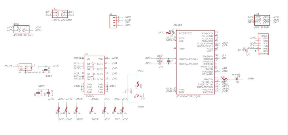
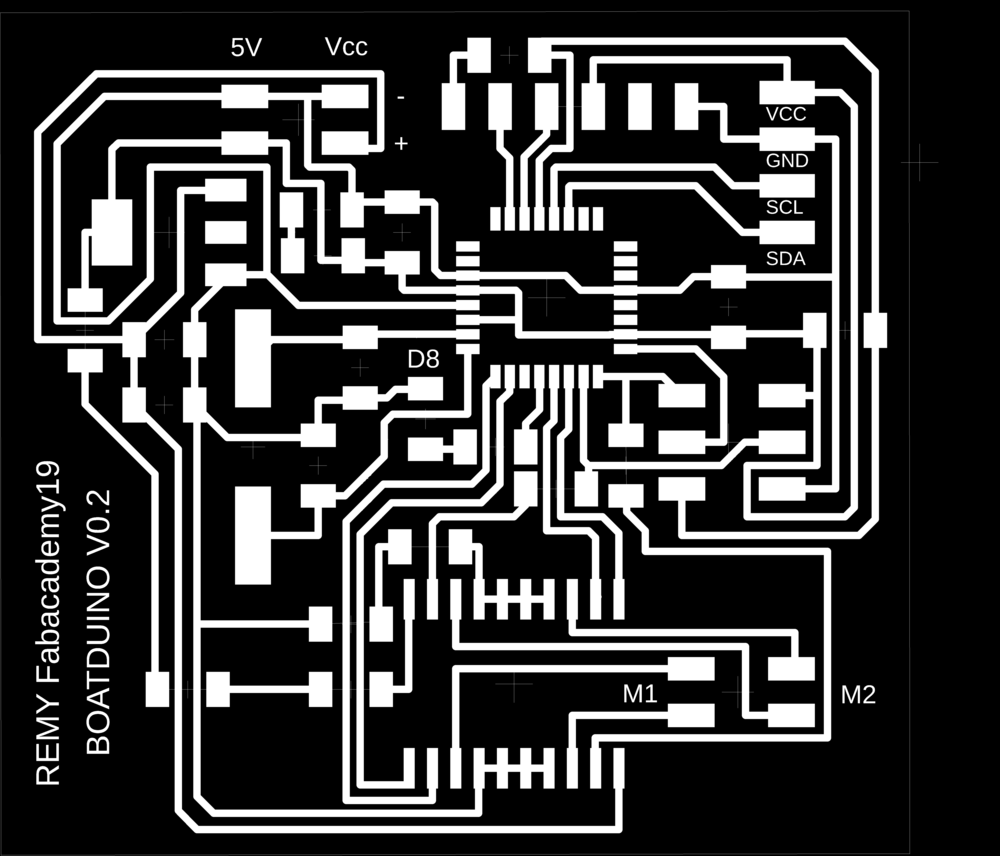
Making of the boatduino V0.2
This board will integrate the motor controls in the board. I’ll have :
- I2C communication pins
- ISP communication pins
- Digital output control
- VCC power supply pin (upto 24V)
- 2 motors connectors
I’ve spent some times in Eagle to merge my Boatduino V0.1 and my Hbridge PCB V2. Here is the result :
 |
 |
Then I made the board using the lasercutter and soldered the components.
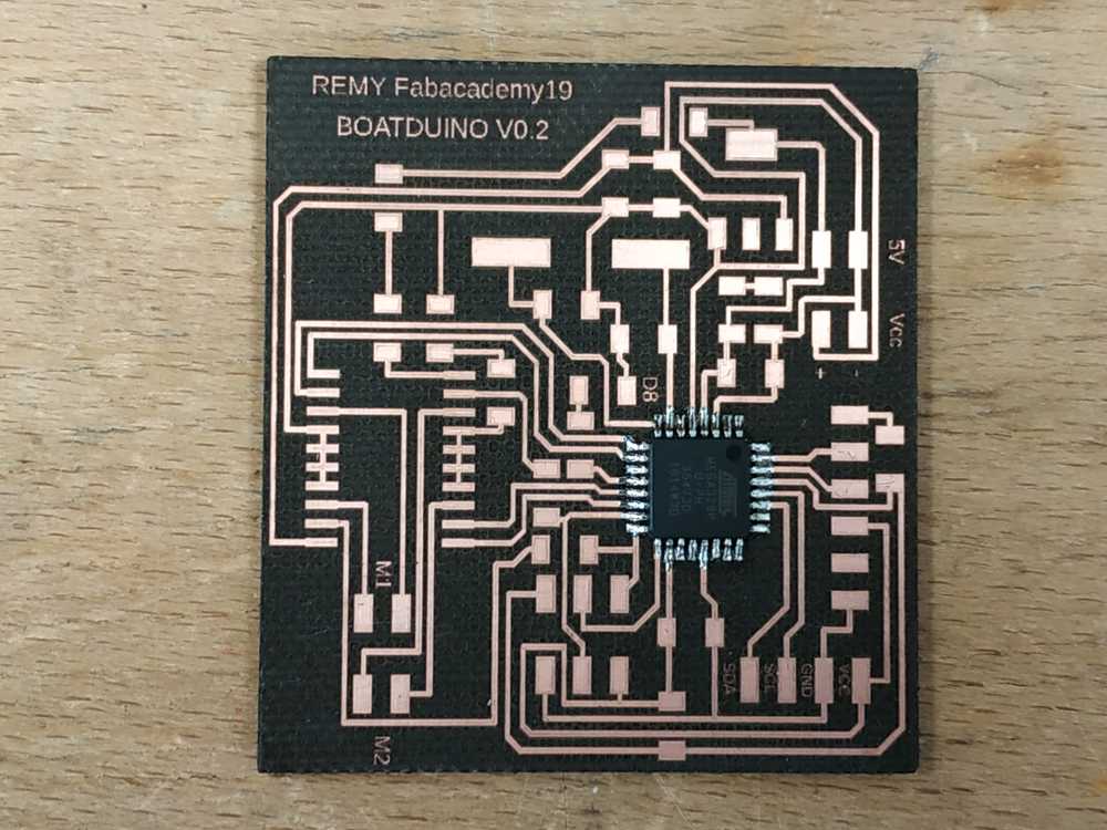 |
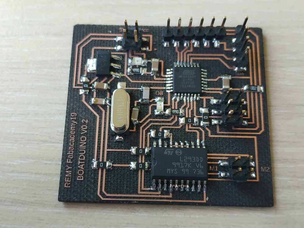 |
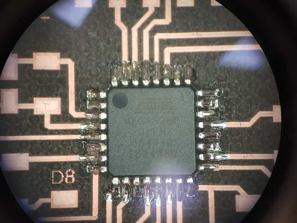
I cheked the connections and soledring using the multimmeter and the oscilloscope.
Everythings semmed good so I plugged it to my arduino board to burn the bootloader.
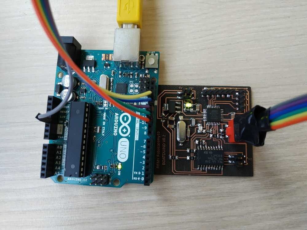 |
 |
Testing the two motors
I then plugged my two motors and uploaded a code to make them behave the way I want with the boat. I simulate the angle of the boat with a potentiometer.
const int controlPin1 = 5; // connected to pin 7 on the H-bridge
const int controlPin2 = 12; // connected to pin 2 on the H-bridge
const int enablePin = 6;   // connected to pin 1 on the H-bridge
int motorEnabled = 0; // Turns the motor on/off
int motorSpeed = 0; // speed of the motor

const int controlPin3 = 9; // connected to pin 7 on the H-bridge
const int controlPin4 = 11; // connected to pin 2 on the H-bridge
const int enablePin2 = 10;   // connected to pin 1 on the H-bridge
int motor2Enabled = 0; // Turns the motor on/off
int motor2Speed = 0; // speed of the motor

int potPin = A5;// Pin of the potentiometer

void setup() {
  // initialize the inputs and outputs
  pinMode(controlPin1, OUTPUT);
  pinMode(controlPin2, OUTPUT);
  pinMode(controlPin3, OUTPUT);
  pinMode(controlPin4, OUTPUT);
  pinMode(enablePin, OUTPUT);
  pinMode(enablePin2, OUTPUT);

  // pull the enable pin LOW to start
  digitalWrite(enablePin, LOW);
  digitalWrite(enablePin2, LOW);
}

void loop() {

  // read the value of the pot and divide by 4 to get a value that can be
  // used for PWM
  motorSpeed = analogRead(potPin) / 4;
  motor2Speed = - (motorSpeed -255);

  // turn on a motor
    digitalWrite(controlPin1, HIGH);
    digitalWrite(controlPin2, LOW);

    digitalWrite(controlPin3, HIGH);
    digitalWrite(controlPin4, LOW);

    // PWM the enable pin to vary the speed
    analogWrite(enablePin, motorSpeed);
    analogWrite(enablePin2, motor2Speed);
}
Evertyhing worked fine :
Testing the two motors with the sensor
Making a dolly
To test my electonics, as I don’t have my boat yet and as I don’t have a huge amount of water available at all times in the Lab, I’ve decided to make a dolly.

I’ve made it the same setup than my boat with two motors to control the direction of the dolly. I’ve made it using cardoard, added a freewheel on front of it. I made a very simple design to place all the components on it. Here are the files/components I used :
| 1 | Dolly.svg |
| 2 | Motors and wheels |
| 3 | Freewheel |
| 4 | 9V battery holder |
I put all the components on the dolly and moved on with the code.
Testing the code
I’ve plugged a breakout board with a MPU6050 communicating using I2C with my boatduino board. To make it work I used the MPU6050 library from @jarzebski (great documentation). I modified the previous code to automatically change the speed of the motors according to the yaw angle. I’ve added the fact that the in-built LED swithes on when the boat goes straight.
#include <Wire.h>
#include <MPU6050.h>

MPU6050 mpu;

//Initialize Motor 1
const int controlPin1 = 5; // connected to the H-bridge
const int controlPin2 = 12; // connected the H-bridge
const int enablePin = 6;   // connected to the H-bridge
int motorEnabled = 0; // Turns the motor on/off
int motorSpeed = 0; // speed of the motor

//Initialize Motor 2
const int controlPin3 = 9; // connected to pin 7 on the H-bridge
const int controlPin4 = 11; // connected to pin 2 on the H-bridge
const int enablePin2 = 10;   // connected to pin 1 on the H-bridge
int motor2Enabled = 0; // Turns the motor on/off
int motor2Speed = 0; // speed of the motor

// Timers
unsigned long timer = 0;
float timeStep = 0.01;

// Yaw values
float yaw = 0;

void setup()
{
  Serial.begin(115200);

    // initialize the inputs and outputs
  pinMode(controlPin1, OUTPUT);
  pinMode(controlPin2, OUTPUT);
  pinMode(controlPin3, OUTPUT);
  pinMode(controlPin4, OUTPUT);
  pinMode(enablePin, OUTPUT);
  pinMode(enablePin2, OUTPUT);
  pinMode(8, OUTPUT);

  // pull the enable pin LOW to start
  digitalWrite(enablePin, LOW);
  digitalWrite(enablePin2, LOW);


  // Initialize MPU6050
  while(!mpu.begin(MPU6050_SCALE_2000DPS, MPU6050_RANGE_2G))
  {
    Serial.println("Could not find a valid MPU6050 sensor, check wiring!");
    delay(500);
  }

  // Calibrate gyroscope. The calibration must be at rest.
  // If you don't want calibrate, comment this line.
  mpu.calibrateGyro();

}

void loop()
{
  timer = millis();

  // Read normalized values
  Vector norm = mpu.readNormalizeGyro();

  // Calculate Yaw
  yaw = yaw + norm.ZAxis * timeStep;

  // Output
  Serial.print(" Yaw = ");
  Serial.println(yaw);

  // Wait to full timeStep period
  delay((timeStep*1000) - (millis() - timer));

  // Map the value of the sensor with the speed of the motors
  motorSpeed = map(yaw, -90, 90, 0, 255);
  motor2Speed = - (motorSpeed -255);

  // Turn on motor1
    digitalWrite(controlPin1, HIGH);
    digitalWrite(controlPin2, LOW);

  // Turn on motor2
    digitalWrite(controlPin3, HIGH);
    digitalWrite(controlPin4, LOW);

    // PWM the enable pin to vary the speed of both motors
    analogWrite(enablePin, motorSpeed);
    analogWrite(enablePin2, motor2Speed);

// Swith on the led if the boat is straight
  if (yaw >= -10 && yaw < 10) {
    digitalWrite(8, HIGH);
  }
  else{
digitalWrite(8, LOW);
  }
delay(10);
}
In this first video, we can see that the code is working as planned.
In this second video we can see that the dolly wants to go back to its initial position if we put it off tracks.

Ce(tte) œuvre est mise à disposition selon les termes de la Licence Creative Commons Attribution - Pas d’Utilisation Commerciale - Partage dans les Mêmes Conditions 4.0 International.