9. Embedded programming
Group assignment
Compare the performance and development workflows for other architectures
Individual assignment
Read a microcontroller data sheet program your board to do something, with as many different programming languages and programming environments as possible
| Documentation | |
|---|---|
| 1. ArduinoShieldISP.PNG | 2. ArduinoShieldISP.cdr |
| 3. ArduinoShieldISP.fzz | 4. ISPConnector.stl |
This week, I will learn how to make my own code and upload it into a microcontroller. I’m going to try different ways to make it work.
The microcontroller datasheet
I’ve been through a microcontroller datasheet. There are many chapters defined, it gives all the important informations we may need to understanding the functioning of the part and its subsystems.
There are according to me, and at my level of understanding of the microcontroller three essential informations in the datasheet :
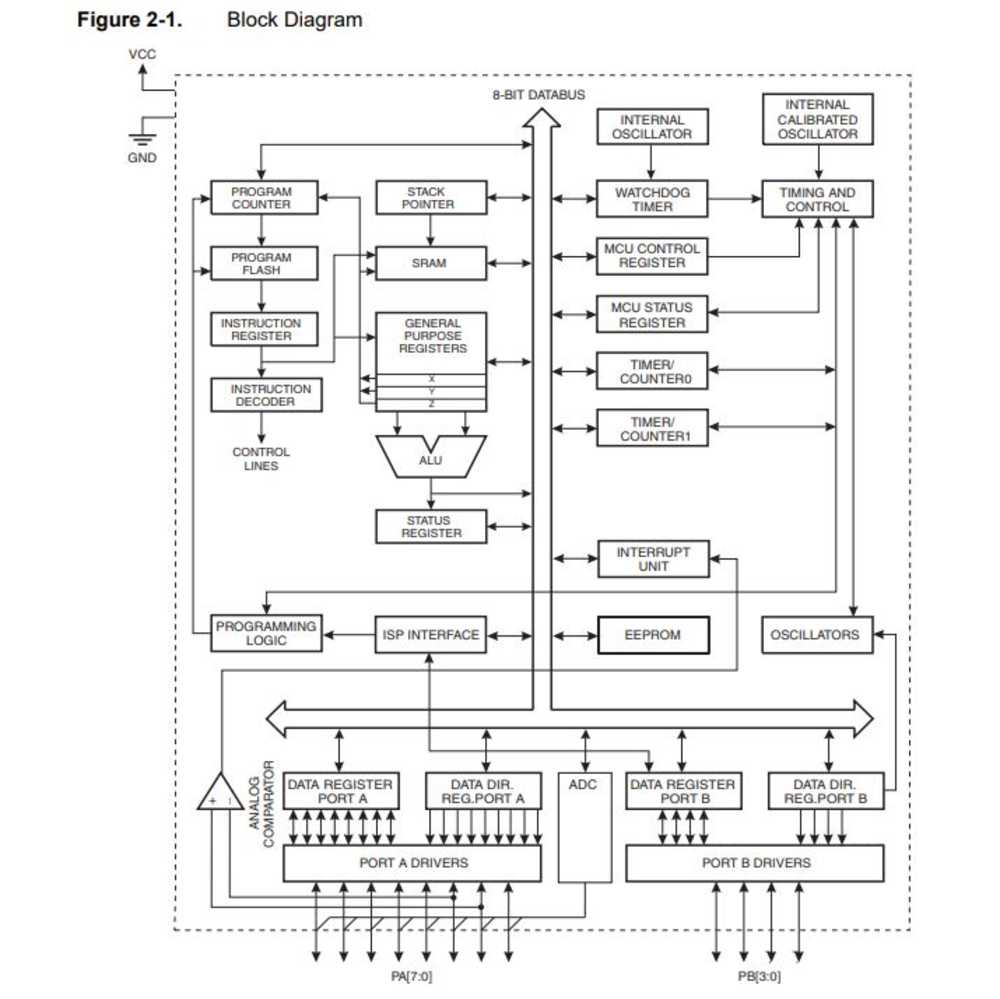
- The Block Diagram where we can see all the subsystems of the microcontroller
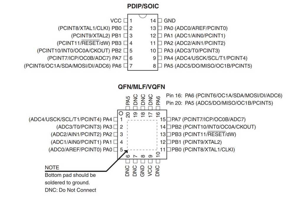
- The Pin out to understand how the pins can be used
- The Absolute maximum rating to understand what are the components we can use with the microcontroller
 |
 |
 |
Using the block diagram we can understand that the microcontroller has registers/memory … It also has the hability to count/set time and do some logical/boolean operations. There are of course much more in the datasheet but these informations are enough for me to get started with.
This week I had to program my hello board. There are three important steps involved in this process :
- Making the code (to get the board do what I want)
- Flashing the code (to transfer the code from my computer to the microcontroller)
- Setting the fuses (to define some important register, such as the clocks)
I tested diferent environment and ways to make these three steps. I’m going to detail those here.
Programming with Atmel Studio
First I used Atmel Studio and Atmel Ice to program my board.
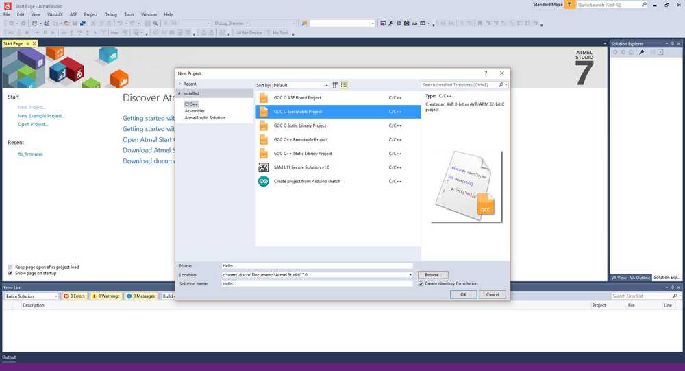
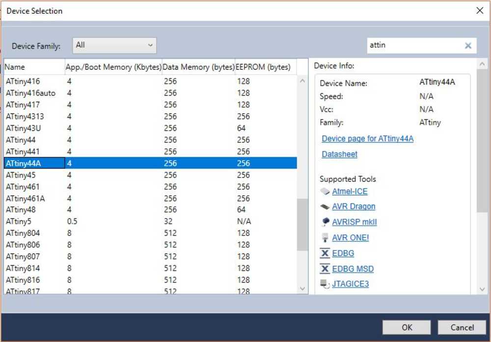
Setting the environment
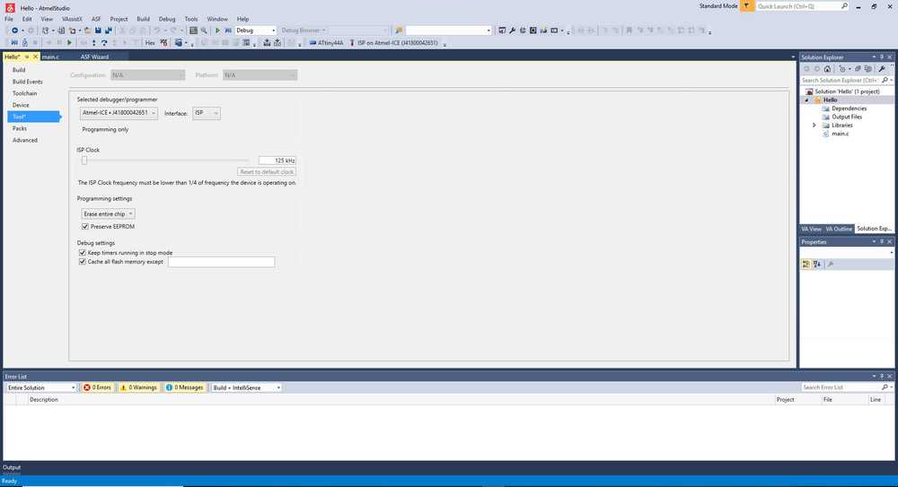
When you start a new project you open a new GCC C Executable Project then select the microcontroller you are using (for me the ATtiny44A). Then by pushing the hamer icon, you have to define the type of ISP you’re using and the communication protocole you are using (here the Atmel Ice and the ISP protocole)
 |
 |
 |
Once this is done, you can make the code for your board
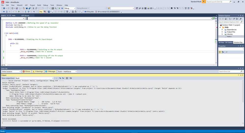
Making the code
In the project, there’s a main.C file. This is where we put the code. We have to code using C language. We can use libraries to call functions to simplify the code. Here’s the code I’ve made just to blink the LED.
/*
 * Hello.c
 * Created: 14/03/2019 13:42:46
 * Author : ducros remy
 */

#define F_CPU 20000000 //Defining the speed of my resonator

#include <avr/io.h>
#include <util/delay.h> //Allow to use the delay function

int main(void)
{
   DDRA = 0b10000000; //Enabling the PA Input/Output

     while (1)
     {
                PORTA = 0b10000000; //Switching on the PA output
                _delay_ms(1000); //Wait for 1 second
                PORTA = 0b00000000; //Switching off the PA output
                _delay_ms(1000); //Wait for 1 second
     }
        return (0); //Compulsory to make the code work
}
NOTE : DDRA = 0b10000000 is a command to fix a register at 10000000. We have in the microcontroller register of 8 bits and each bit defines a pin (PA0, PA1, PA2 …). Here settings 0 means that the pin will be an input and 1 an output. For example here by difning the register DDRA = 0b10000000 I have :
| PA0 | INPUT |
| PA1 | INPUT |
| PA2 | INPUT |
| PA3 | INPUT |
| PA4 | INPUT |
| PA5 | INPUT |
| PA6 | INPUT |
| PA7 | OUTPUT |
EXTRA : To check the state of a pin (Low or High), we have to check a register where the value of all the pins are defined (using 0 as low and 1 as high) then we have to make a boolean operation with the register we used to define the input/output. According to the result of this operation we can define the state of a pin and start an action accordingly (for example while I push a button, I can switch on a LED)
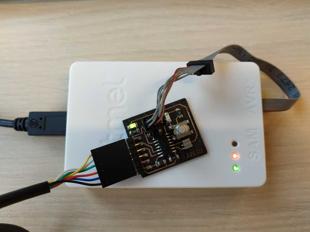
Flashing the code with Atmel Ice
To flash the program you have to connect the ISP of your board with the atmel ice. The board also needs an externe power supply to run (here I used my FTDI cable).
If your settings and your program are good, then by clicking on Start without Debugging it will upload your code. You’ll see if a message informing you that everything went on well.
 |
 |
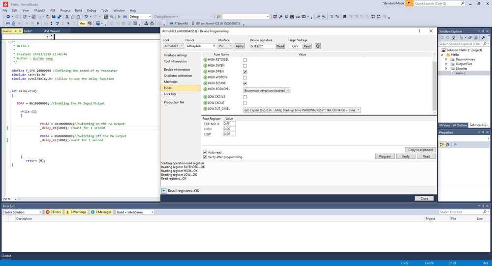
Setting the fuses
After flashing the board, the LED was blinking but the timing were off. The system was in fact using the 8MHz in build resonator to mesure the time and not the 20MHz resonator, I’ve added to the board. To modify that, I went directly to the fuses section of the software. Here I changed two of them :
- I disabled LOW.CKDIV8 which divided the time by 8
- I changed the LOW.SUT_CKSEL so it was not using the interal clock but my external resonator. Also in my code I
#define F_CPU 20000000so the delay library will understand what to use as reference for the time.
This is a complete workflow to program my board. Here’s a video of it working :
Programming with arduino environment
The arduino environment is a complete workflow as well (harware and software) to make embedded programming. Here I’m going to use the IDE to make my program and the Arduino Uno as an ISP to flash my program into my board.
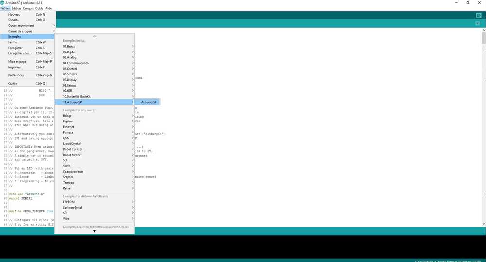
Setting the environment
First you have to upload a code into the arduino so it behave as an ISP. To do so, just go to file/example/11.ArduinoISP and flash the ArduinoISP program to the board.
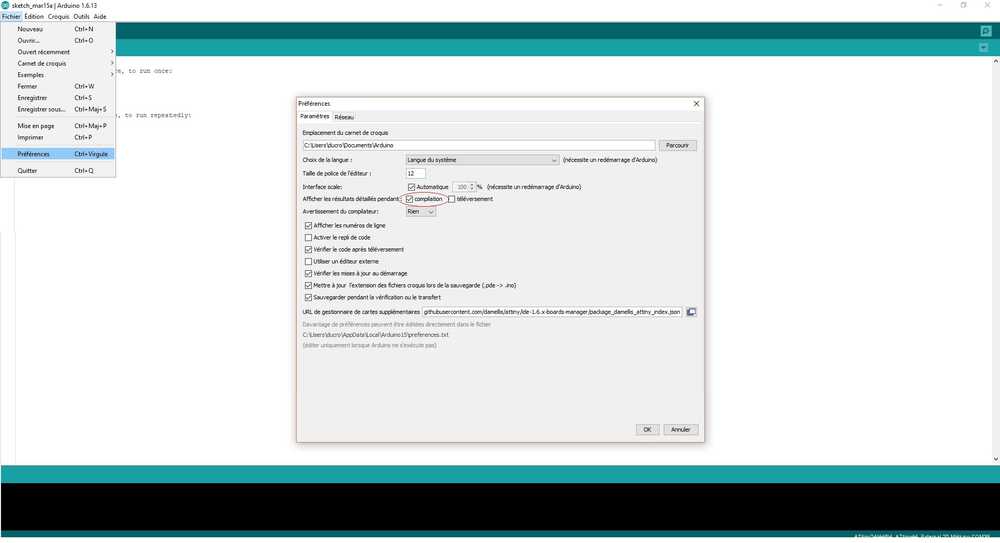
Then go to file/preferences and do the following :
- Select the option to get the detailed results while compiling. It will allow us to see what’s going on during the compilation process
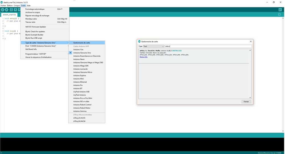
- Add the URL
https://raw.githubusercontent.com/damellis/attiny/ide-1.6.x-boards-manager/package_damellis_attiny_index.jsonto manage extra boards to use the ATtiny family.
 |
 |
Then you can go to the board manager and install the ATtiny package to be able to use microcontroller from the ATtiny family. Once this is done you can define in the Tool section, the Family of microcontroller you are using (ATtiny), the board you are using (ATtiny44), the external clock you are using (20MHz). Then it’s also important to define the Arduino as ISP.
 |
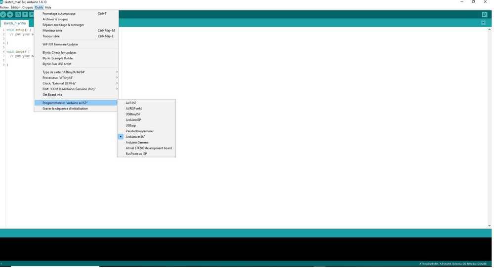 |
Once everything is done, we can make our own program.
Making the code
Her we code using the Aduino language, which is a simplified version of C-code. Here also we can use libraries to simplify the code. However, while we are defining the pins we are using, we have to be careful to use the correct ones as the pins for the arduino and the Attiny are not the same. Hopefully we can find very handy diagrams to help us out :
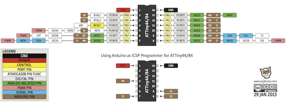
I made a code to blink my LED :
// the setup function runs once when you press reset or power the board
void setup() {
  // initialize digital pin 7 (PA7) as an output.
  pinMode(7, OUTPUT);
}

// the loop function runs over and over again forever
void loop() {
  digitalWrite(7, HIGH);   // turn the LED on (HIGH is the voltage level)
  delay(1000);                       // wait for a second
  digitalWrite(7, LOW);    // turn the LED off by making the voltage LOW
  delay(1000);                       // wait for a second
}
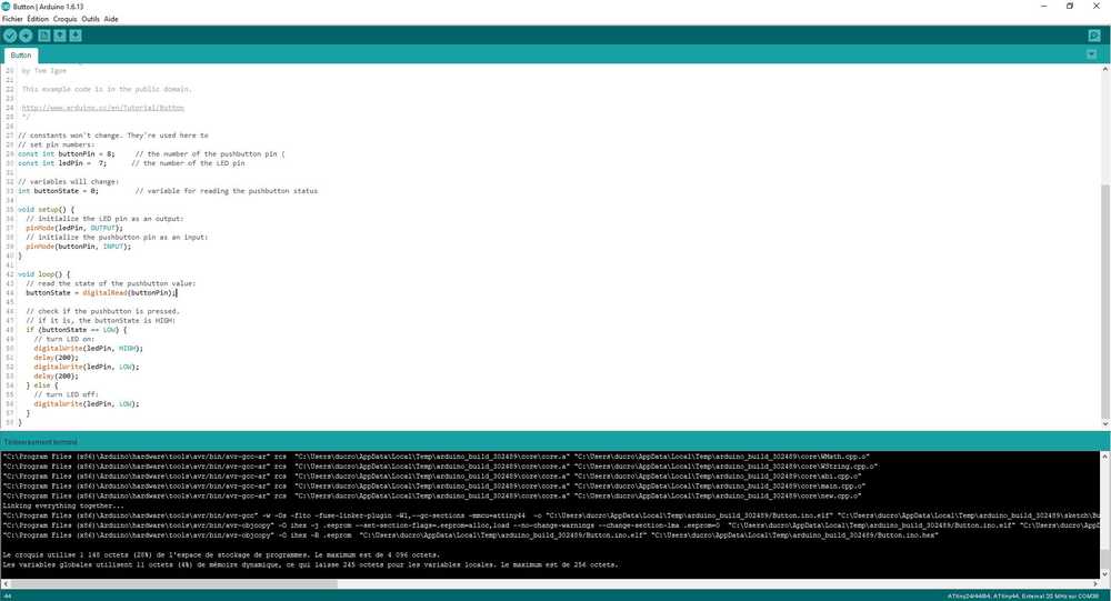
And another one to make the LED blink while pushing the button :
// constants won't change. They're used here to
// set pin numbers:
const int buttonPin = 8;     // the number of the pushbutton pin (PB2)
const int ledPin =  7;      // the number of the LED pin (PA7)

// variables will change:
int buttonState = 0;         // variable for reading the pushbutton status

void setup() {
  // initialize the LED pin as an output:
  pinMode(ledPin, OUTPUT);
  // initialize the pushbutton pin as an input:
  pinMode(buttonPin, INPUT);
}

void loop() {
  // read the state of the pushbutton value:
  buttonState = digitalRead(buttonPin);

  // check if the pushbutton is pressed.
  // if it is, the buttonState is HIGH:
  if (buttonState == LOW) {
    // turn LED on:
    digitalWrite(ledPin, HIGH);
    delay(200);
    digitalWrite(ledPin, LOW);
    delay(200);
  } else {
    // turn LED off:
    digitalWrite(ledPin, LOW);
  }
}
Here’s a video of it working :
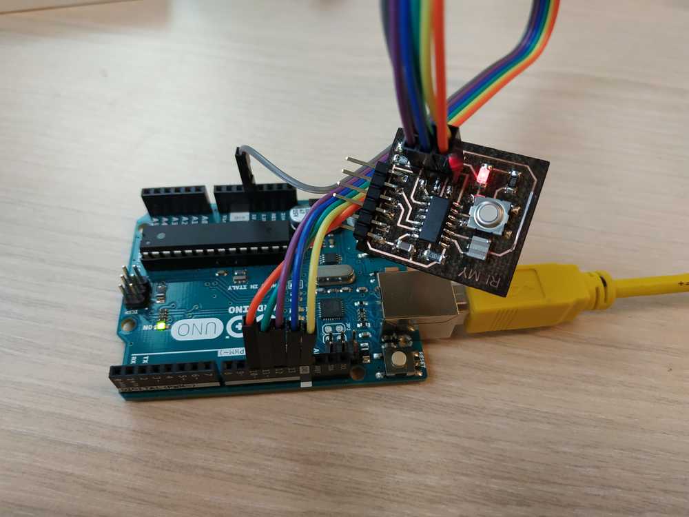
Flashing the code
To flash the ATtiny, I connected the pins 10 to 13 and the 5V and GND to the ISP port of my board. Then if all the previous settings are correctly made, we can upload the code. If everything went on well, the code is in the board and we can test it.
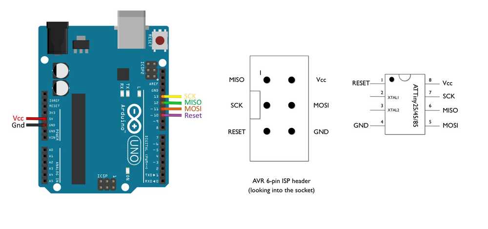 |
 |
 |
NOTE : Here my board doesn’t need an external power supply as it will come directly from the arduino board itself. I also didn’t set the fuses in this environement but it’s not a problem as I can do it using AVR dude or Atmel Studio.
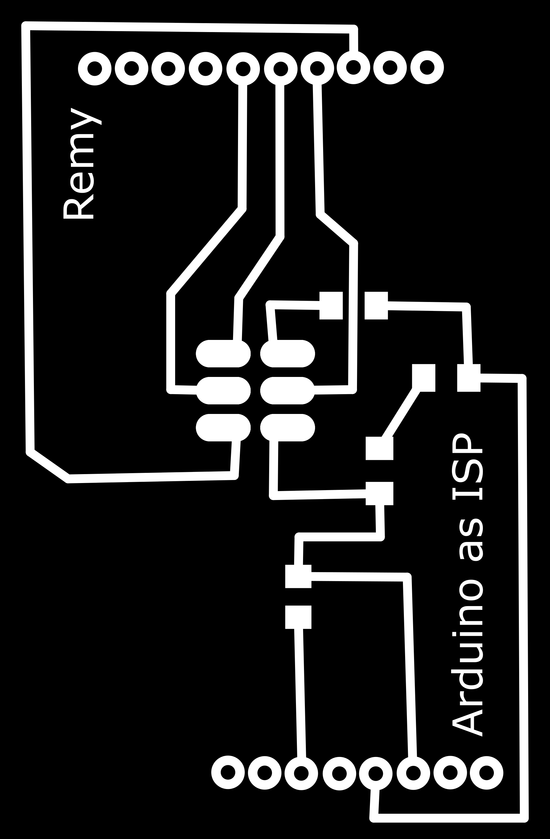
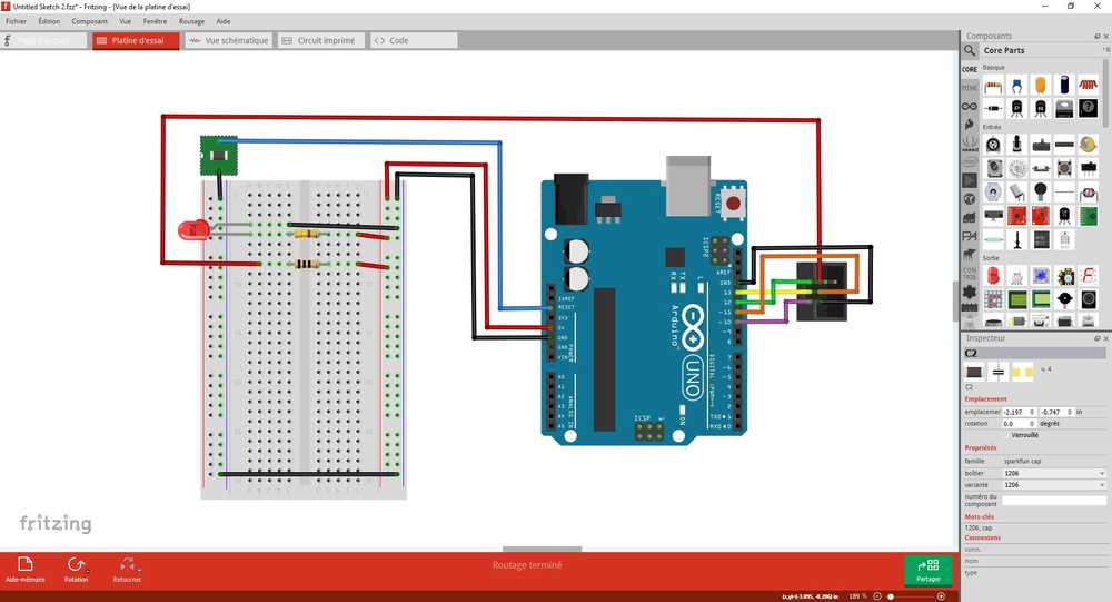
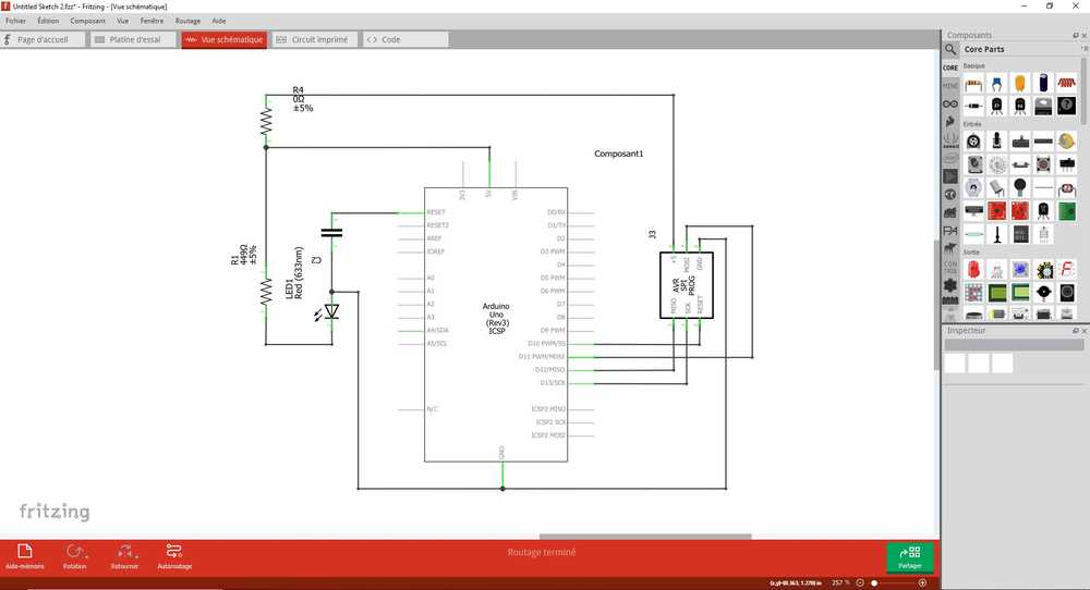
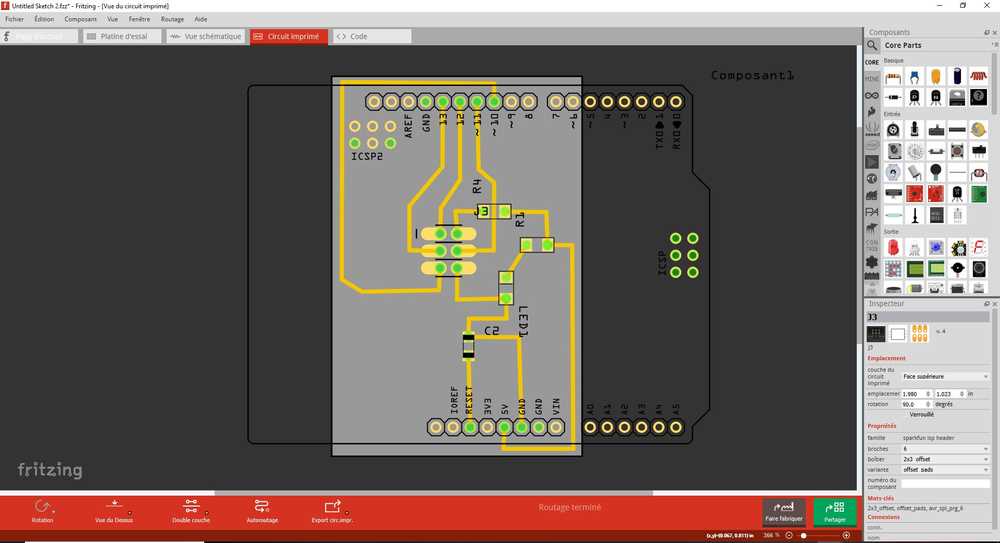
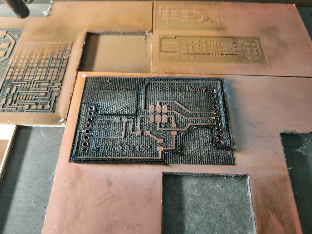
Making an Arduino as ISP Shield
I like the fact that I can use the Arduino environment to make my codes as I’m used to it but having to pin some wires is not very handy so I decided to go for my version of a shield to connect directly to ISP male connector. As I used Eagle during the electronic design week, I’ve decided to try Fritzing this time. I made my board, added a LED to make sure the shield is connected properly then, I saved the file as an SVG.
 |
 |
 |
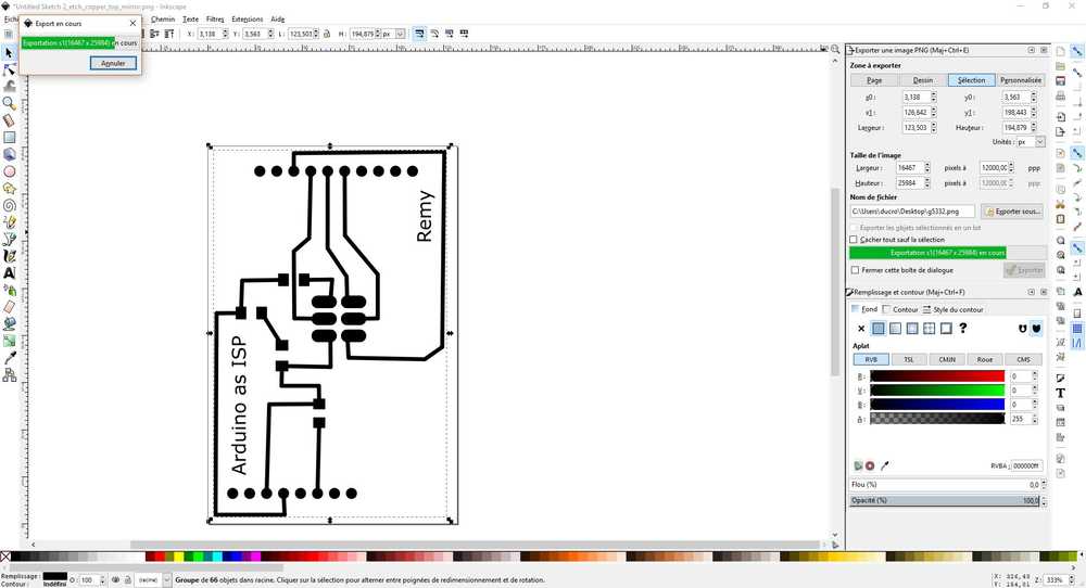
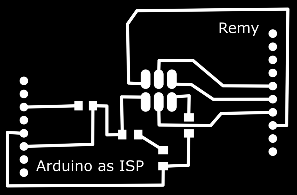
Then I used Inkscape to make some adjustment, modifying some jonctions, adding some text. Then I made a negatif of the image, and raster it in the lasercutter.
 |
 |
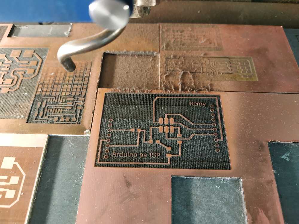 |
I used Coreldraw to make the contour then I cut the board. I cleaned it an solder the components.
 |
 |
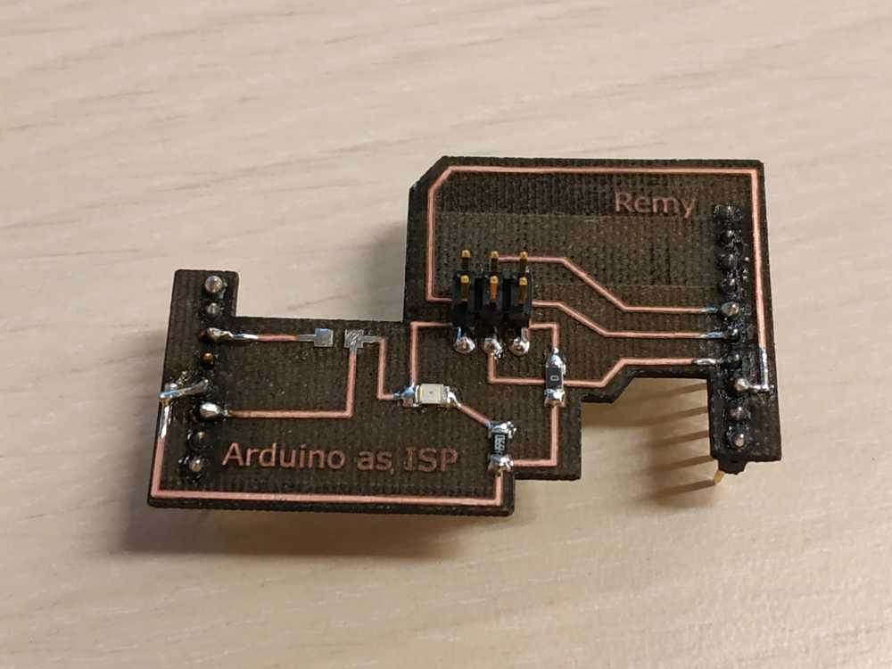 |
NOTE : Mistakes were made. I cut to much and it damaged some paths, so I tried to solder the pins but I needed to had a pin header to make a connection. The file I’m sharing (at the top of this page) is modified accordingly.
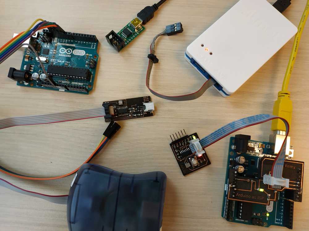
Then I just have to plug my hello board to make some more tests :
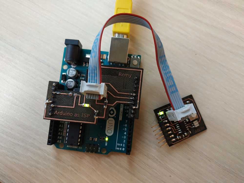
NOTE : The shield is working fine to supply the board but I didn’t managed (yet) to use it as an ISP. I checked my connections and modified one, I removed the capacitor (I didn’t use it in my previous test and it was working well). I have two options to test yet :
- Removing the LED (maybe it uses too much current)
- Make some wire connection were I damaged the paths
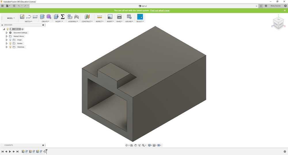
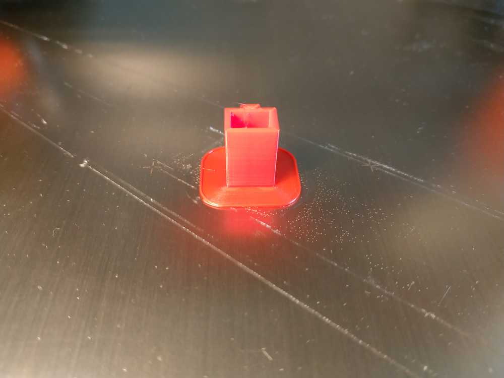
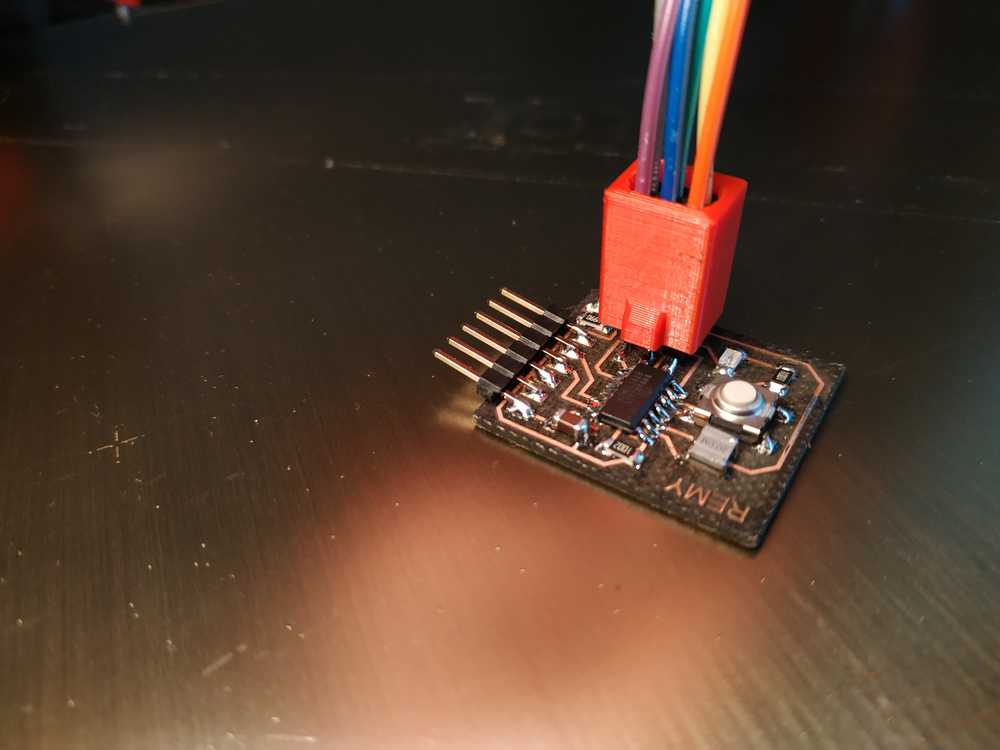
Waiting to make it work, I designed a plastic part I 3D printed, to hold the wires together with an indicator so I plug my ISP connector the correct way.
 |
 |
 |
Flashing using AVR dude
To use AVR dude, there’s a whole toolchain to configure first. I documented this during my Week05. Assuming everything works well we can now move on and use AVR dude.
Making the code
There are two ways to make the code :
- Writing it in plain C and saving it in a file.
- Writing the code in arduino IDE
Flashing the code
To flash the code we need an .HEX file because the microcontroller only understand Hexadecimal.
If we made a C file we need to transform it in HEX file before flashing. We can use AVR dude for that and I’ve documented the process during my Week07.
Using the arduino IDE when we compile the code (and if we set everything properly) we can see some GCC compilation being made and when it’s all done, we can see that the software created an HEX file and it gives us where it’s stored in the computer.
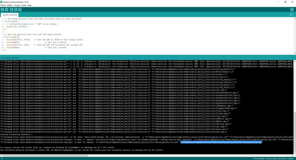
NOTE : The file is stored in a hidden folder, to access it, the easiest way is to search for %appdata% in cortana.
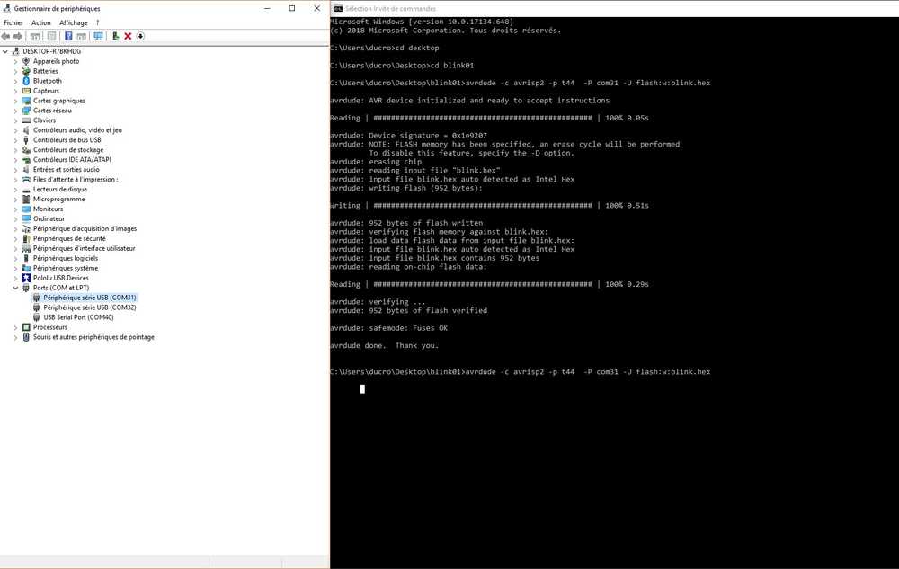
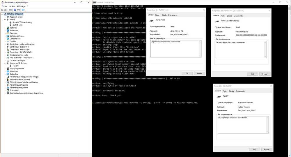
Once we have the Hex file we have to plug any ISP to the board we want to connect. Then we have to check in which COM, the ISP is pluggeg in and get the AVR code so the ISP is identified by AVR dude.
Then we have to run the command : avrdude -c avrisp2 -p t44 -P COM31 -U flash:w:blink.hex
If everything runs properly, we have a succesful upload message and the code runs in the microcontroller.
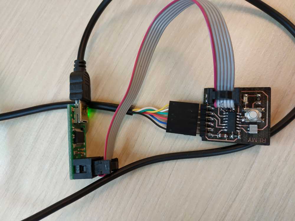
NOTE : For this test I tried different ISP :
- PoluluISP
- My fabISP
- MKII ISP
- Atmel ICE
Here I can get the COM only with the Polulu so I could make it work only with this ISP.
 |
 |
 |
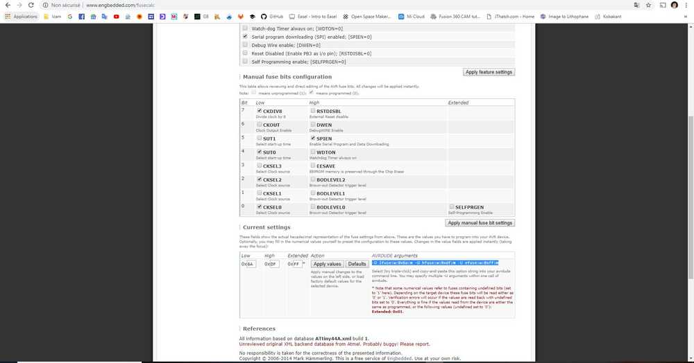
Setting the fuses
To set the fuses we can use this online calculator. It’s helping us in a visual environment to get the fuses the way we want and it provides the AVRdude command we have to run.
Pros and Cons
Overall there are many ways to program a microcontroller. Here are my thoughts on what I’ve experimented :
ATMEL STUDIO
| Visual environment | Need an expensive ISP to run |
| Low level of integration | Uses C code |
| Uses C code | We need extra power suply to program the board |
AVR DUDE
| Low level of integration | Not a visual environment |
| Works with many ISP | Need a complicated toolchain to run (on windows) |
| Uses C code | Uses C code |
| We need extra power suply to program the board |
Arduino
| Visual environment | Not a low level of integration |
| Works with an arduino as ISP | Doesn’t support the fuses well |
| Uses Arduino code | Doesn’t uses C code |
| No need extra power suply to program the board |
NOTE : I put the fact to use C code as a good thing as we have a whole control on it and nothing’s hidden. I put it as a bad thing as well, because I don’t know how to code well enough in C while I’m used to the arduino code. I’m aware that the arduino code is less efficient and that my program may run slower but for the level of design I’m making, it will be more then enough. If not I can go deeper into C code as I know it exists.
After doing all these tests I found the most efficient way for me to work is :
- Making the code using arduino
- Flashing the code using arduino as ISP
- Using Atmel studio to visualize how my microcontroller is running and to set the fuses
I know it’s definetly not the most efficient way to work but it is for me, my need, and the time I could spend on this project.

Ce(tte) œuvre est mise à disposition selon les termes de la Licence Creative Commons Attribution - Pas d’Utilisation Commerciale - Partage dans les Mêmes Conditions 4.0 International.