 Erwin Kooi
Overview
My final project is a puzzle box.
Basically an inverted escape room where the purpose is to solve all the puzzles and get to the treasure inside. The puzzles have a relation to each other so they have to be solved in sequence.
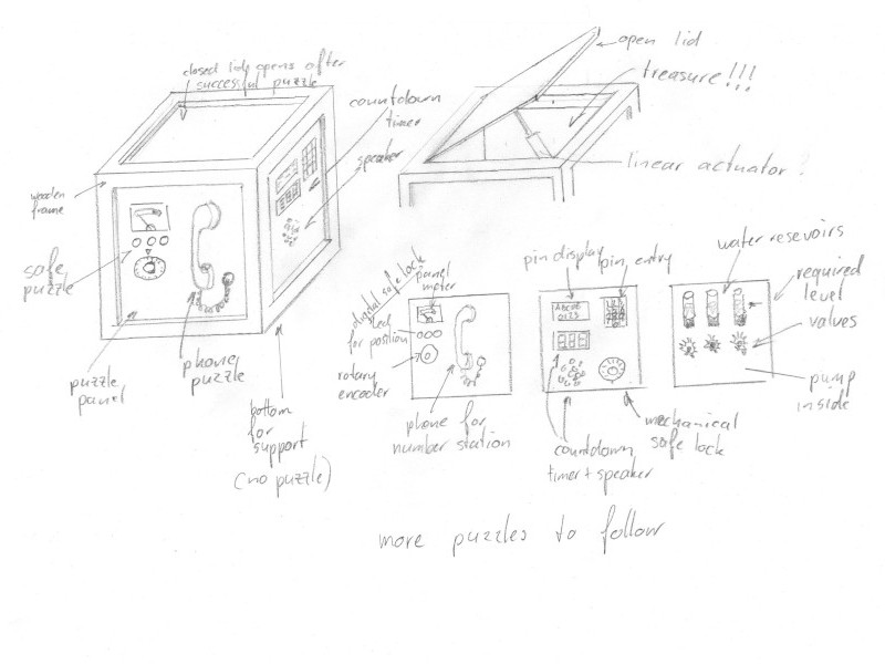
The first ideas were drafted in week 1.
One of my main inspriations was on the Youtube channel of Chris Ramsay. He basically can make a living by solving other people’s puzzles and people send him the boxes they designed.

There is not much on the design of the inner workings, as this would spoil a lot of the game play. Most of the things have to be worked out by myself.
After a life-long quest, you have finally found it!
At the top of an old tower in the hidden lab of a crazy scientist, you have found this misterious box.
Some rumours say it will end the world, other rumours say it will prevent the end of the world. It is up to you to find out and make the final decision.
There are six faces on a box. The bottom will not be used for a puzzle. The top will contain the start button. That leaves four sides for puzzles.
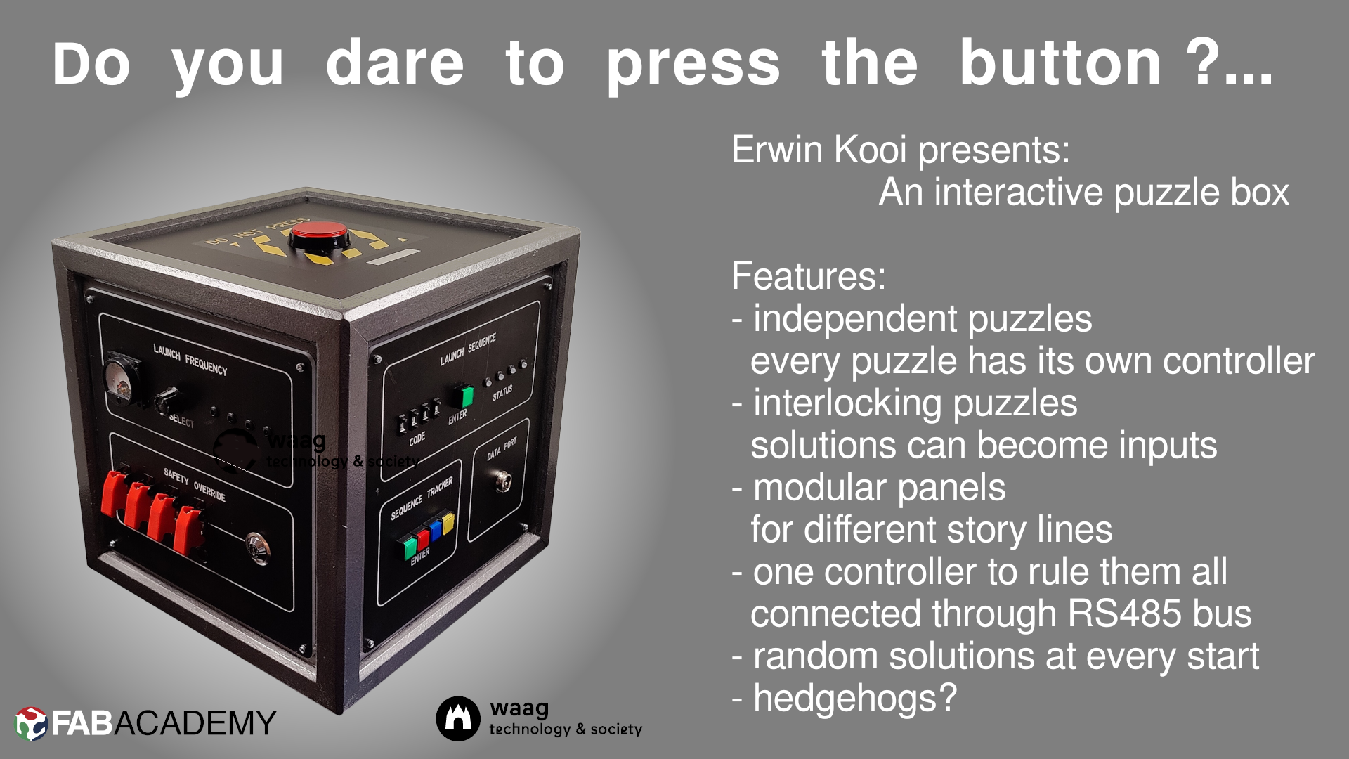
Possible themes are “old lab equimment”, “old radio equipment” or “steampunk”. I really like the steampunk, but that would be very time consuming. I will use “rocket launch panel” for now. The infrastructure of the puzzle can easily be adapted for other types of puzzles.
The frame is designed in FreeCAD (as reported in week 2) and made from left-over wewd from a carpenter. He makes window sills and has all kinds of scraps laying around. The frame panels are made from 5 mm plywewd.
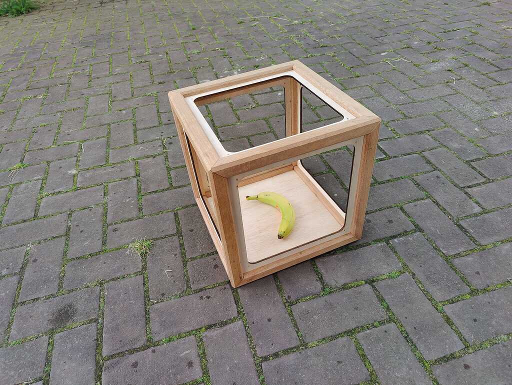
(Banana for scale.)
There is a dedicated page on the construction of the frame.
The puzzle panels are are designed in InkScape (as reported in week 3) and made from 4mm white acrylic that is painted black and then engraved with a laser cutter.
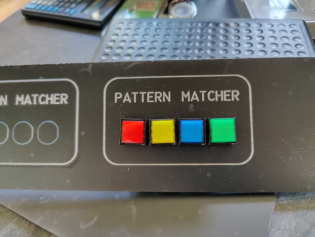
There is a dedicated page on the construction of the panels.
The main reason for not fixating the puzzle panels to the frame is modularity. It is now possible to exchange panels and make a different story line.
The electronics are designed in KiCAD (as reported in week 6) and made from FR1 PCB blanks in a CNC mill (as reported in week 4).
Each puzzle has its own PCB with a generic part for communication and a dedicated part for the puzzle interface. This makes designing a PCB for a new puzzle relatively easy.


There are dedicated pages on the design and construction of each puzzle.
All electronic components are sourced from DigiKey.
The switches are mostly scavenged from old panels. The other switches are sourced from two small electronics shop that focus on makers, Kiwi-electronics and TinyTronics.
Since each puzzle has its own microcontroller, each puzzle has its own code (as reported in week 8). It leans strongly on the different types of inputs (as reported in week 10) and outputs (as reported in week 12).
Just as the PCB’s have generic parts for commuication and dedicated parts for the puzzle, the code also has generic parts for communication and dedicated parts for the puzzle. This is documented in the code.
The code is written using the native control registers of the attiny3216. THere are no 3rd party libraries used. This gives great flexibility, especially when writing the communication part. It also gives a very small code size. The largest code (for the Launch Sequence) fits easily in an attiny412.
This is an interesting avenue to research, using an attiny412 (because I can) and a PCA9555D i2c port expander…
The code for the puzzles is included on the dedicated puzzle pages.
The central controller needs to communicate with the individual puzzles.
This is done using an RS485 network. The attiny’s have a special RS485 mode, where the microprocessor switches the RS845 tranceiver in send- or receive-mode, depending on wether it has to send or receive data. One of the pins is marked XDIR in the datasheet and can be set to this function using a control register. Unfortunately I discovered this after I had created the PCB’s and I had selected a different pin for this function. Now I have to solve this in software.
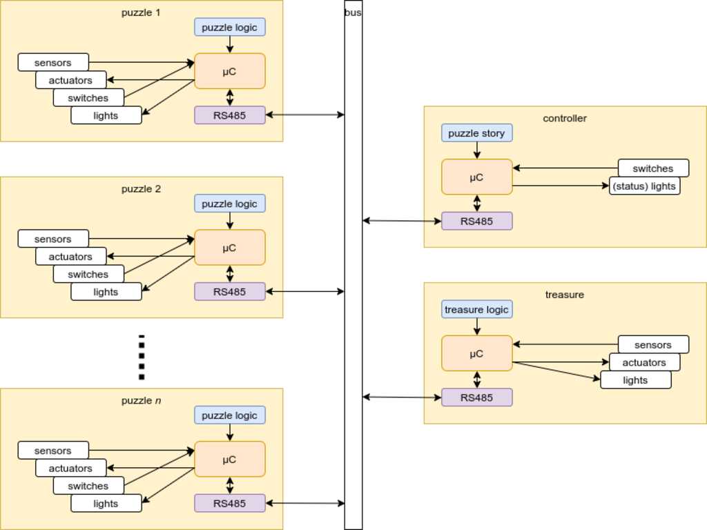
The protocol uses the special 9-bit MPCM mode of the attiny microcontroller (as reported in week 13). The hardware of the attiny will detect if the received frame is an address or data and if it is not addressed, completely ignore the data. This will not generate any interrupt for the microcontroller that will continue its program if no data has passed on the wire.
Solving the puzzle will lead you to the treasure. This has not been implemented yet.
Neil gave a very good idea, based on the foam crawler by Daniel Meyer. It has a reflective side that will become translucent when the internal light is turned on, showing the insides of the box.
This is something to research further.
Adding it is relatively easy, as the treasure will be controlled by the central controller like any other puzzle.
The modularity of the design allowed for a very spirally approach.
Each puzzle can be a spiral, after the mimimal set has been made to show the succesfull operation.
The parts for the digital safe puzzle (Launch Frequency) have already been constructed, but I didn’t have enough time to integrate them in the panel. This is future work.
I think I have documented my work well, so anyone with an interest can reproduce it. I have linked to the various skills taught by FabAcademy that were used to conceive, design and create this project.
- 2d design? check, in the puzzle panels.
- 2d construction? check, laser cutting the puzzle panels.
- 3d design? check. in the frame construction.
- 3d construction? check, in the frame construction and the 3d-printed knob on the digital safe puzzle. ;-)
- pcb design? check, in the various pcb’s of the puzzles.
- embedded programming? check, in the various microcontrolelrs of the puzzles.
- interfacing? check, in the MPCM communication protocol between the puzzles.
- Inputs and outputs? check, in the various knobs, dials and LED’s of the puzzles.
- packaging? check, the box is a complete (but still expandable) work that is compelling to play. Wires are routed cleanly between the componentes and flatcable is used between boards.
I would like to continue expanding this puzzle and donate it to the node. It can be an eye-catcher on open days, hopefully intrigue prospecting students to start their journey with FabAcademy.
Trying to combine FabAcademy with a full time dayjob and a life at a farm can be very challenging at times. The available time, the assignment and my drive to get the most out of it lead to some cut corners in other parts of my life.
I am very fortunate to have understanding and supporting colleagues and especially fortunate to have an understanding and supporting wife. Without her I would not have been able to complete FabAcademy in time. <3