 Erwin Kooi
Soldering exercise
Bootcamp is here!
This is a great way to get up to speed with some basic skills you will use throughout FabAcademy.
One of these skills is soldering. Using tiny bits of molten metal to bind elektrical components together, typically on a printed circuit board. Skills are developed with practice, so I created a small board that will help you practice and will give you a fun nametag in the end.
Don’t worry if you do not understand the text below, it will all become clear when you progress in FabAcademy.
NOTE
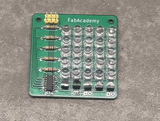
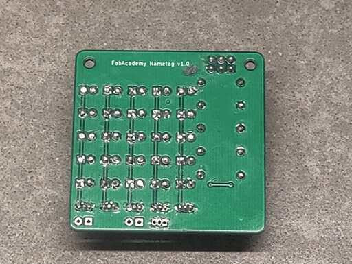
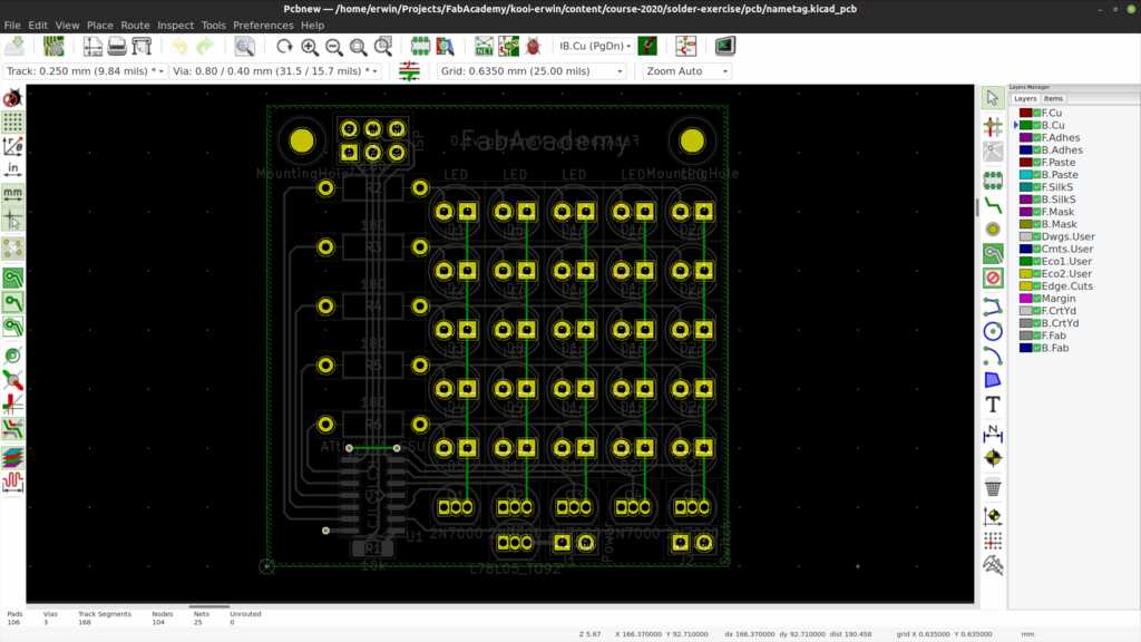
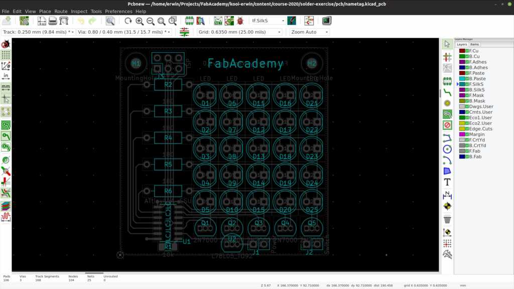
These pictures are from the 1.0 version, the 1.1 version has added capacitors.
Functionally, there is no difference
The design is based on an AVR ATtiny44 microcontroller. This is the older version of the ATtiny series, but there are still plenty available at the FabLab and this a good use for them.
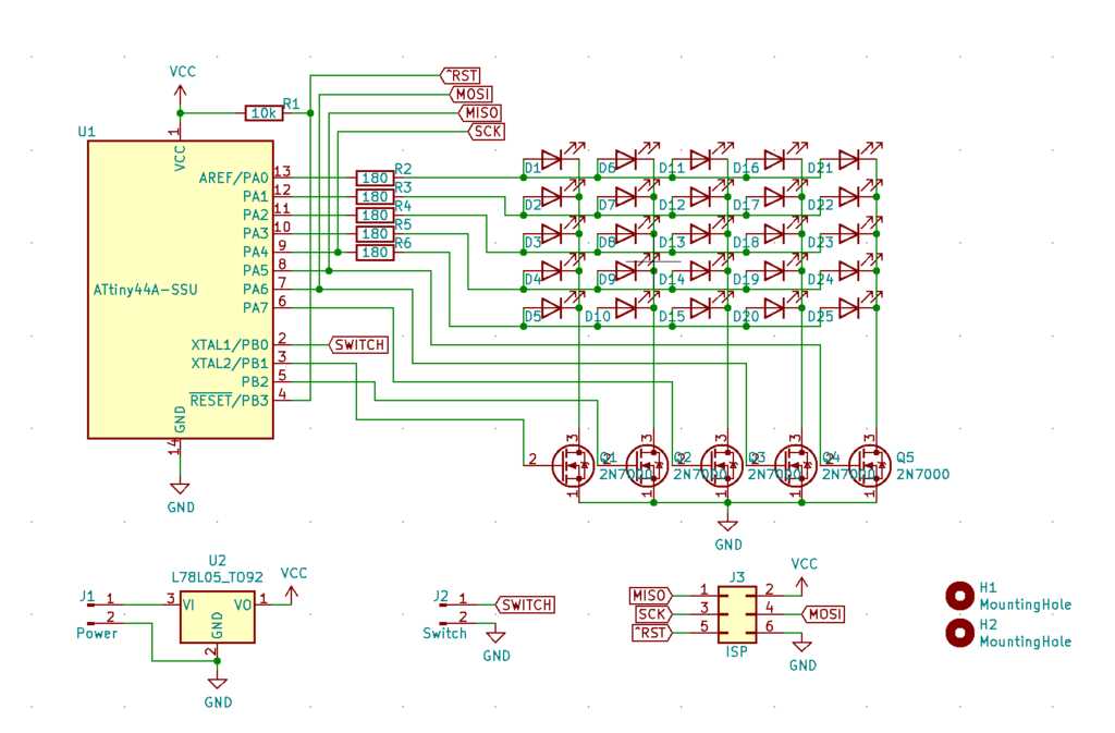
The LEDs are placed in a matrix. The microcontroller drives one of the FETs HIGH, selecting a column of LEDs. The rows are then lit, depending on which pixels should be shown in that column.
By strobing the columns very quickly, the human eye will perceive the columns as always lit.
A FET is used, because these LED can draw (5V - 1.8V) / 180Ohm = 18mA. One microcontroller pin can drive 50mA, so lighting an entire column would require the pin to handle 90mA. The FET can handle this higher current without a problem.
A 78L05 is used to provide a steady 5V power, even if a 9V battery is connected to the power input.
Programming is done via the ISP connector. This connector expects the programmer to supply it with 5V!
One I/O pin of the ATtiny44 is free and it is routed to a “switch” connector. This can be used in the future to expand the functioning of the nametag.
The Bill of Materials (BoM) for the required components is listed below:
| Reference | Type | Value |
|---|---|---|
| R1 | Resistor | 10k |
| R2 - R6 | Resistor | 180 |
| C1 - C2 | Capacitor | 100n |
| D1 - D25 | LED | red 5mm |
| Q1 - Q5 | N MOSFET | 2N7000 |
| U1 | Microprocessor | ATtiny44A |
| U2 | Voltage regulator | L78L05 |
| J1 - J2 | Connector | PinHeader 1x2 |
| J3 | Connector | PinHeader 2x3 |
The program is based on two important loops.
- One loop to update the columns of the matrix so fast that our eyes perceive the complete matrix to be on all the time. This is called Persistence of Vision (PoV).
- One loop to shift the contents of the matrix so the text appears to be scrolling.
The PoV loop is managed by having hardware timer1 generate interrupts. This timer is configured as a Clear-Timer-on-Compare (CTC) mode. This is done by setting the correct bits in the TCCR1B control register.
In this mode, the timer will increment an internal counter (tick) and will trigger an interrupt when this counter reaches a pre-set number.
This number is stored in register OCR1A. It can be calculated by the formula F_CPU / PreScaler * seconds. So in this case, 1000000 / 64 * 1 = 15625 ticks per second, or 16 ticks per millisecond.
OCR1A is set to 32, meaning an interrupt every 2 milliseconds. Since the matrix has 5 columns, this will result in a complete cycle of 10 milliseconds, or 100 Hz.
  TCNT1 = 0;                        // count from zero
  OCR1A = 16 * MATRIX_POV_TIME;     // count up to this value for PoV effect 16 = 1ms
  TCCR1B |= _BV(WGM12) |            // set counter to CTC mode
            _BV(CS11)  | _BV(CS10); // set clock divider to 64 = 15625 ticks per second
  TIMSK1 |= _BV(OCIE1A);            // enable interrupt on CTC mode for OCR1A
When the interrupt is triggered, a number of things occur. First the next active column is set.
ISR(TIM1_COMPA_vect) {                    // a timer interrupt has occurred
  ledMatrixPtr++;                         // select the next active column
  if (ledMatrixPtr >= MATRIX_NUM_COLS) {  // check if we are at the last column
    ledMatrixPtr = 0;                     // start again at the first column
  }
Then all columns are switched off, the matching row-data is loaded and only the correct column is switched back on.
  ledMatrixShiftCtr++;                    // increment the matrix shift timer

  PORTA &= 0b00000000;                    // clear port A
  PORTB &= 0b11111001;                    // clear port B
  PORTA |= ledMatrixArray[ledMatrixPtr];  // load character line

  if (ledMatrixPtr == 0) {                // Set active column 0 (right)
    PORTA |= 0b00100000;
    PORTB |= 0b00000000;
  }
  if (ledMatrixPtr == 1) {                // Set active column 1
    PORTA |= 0b01000000;
    PORTB |= 0b00000000;
  }
  // etcetera
}
The interrupt in the PoV loop increments a counter, so every 2 ms an increment occurs. After 50 increments (= 100 ms), the matrix loop is triggered.
ledMatrixShiftCtr++; // increment the matrix shift timer
This is done in the main part of the program. If the counter reaches the specified amount, the content of all columns is shifted one position to the left and new content is inserted in the most-right column. This content is taken from the next column of the currently displayed character.
    if (ledMatrixShiftCtr >= MATRIX_SHIFT_CTR) {          // shift the matrix in time
      ledMatrixShiftCtr = 0;                              // reset the counter

      ledMatrixArray[4] = ledMatrixArray[3];
      ledMatrixArray[3] = ledMatrixArray[2];
      ledMatrixArray[2] = ledMatrixArray[1];
      ledMatrixArray[1] = ledMatrixArray[0];
      ledMatrixArray[0] = pgm_read_byte(&fontArray[(fontPtr * FONT_CHAR_WIDTH) + fontCharPtr]);
If there are no more columns in the character, the next character is selected for display.
      fontCharPtr++;                                  // increment to get the next row in the character
      if (fontCharPtr >= FONT_CHAR_WIDTH) {           // check if we are done with this character
        fontCharPtr = 0;                              // start again from the first row

        namePtr++;                                    // get the next character
If there are no more characters to display, the first character is selected again. Because the number of characters depend on the name being displayed, the size is calculated on the fly using the sizeof() function.
        if (namePtr >= (sizeof(nameArray)/sizeof(char))) {// check we are at the last character
          namePtr = 0;                                    // start again from the first character
        }
When a new character is selected, a quick check is done to see if this character can be displayed. At this moment, only uppercase characters are in the font. Any non-uppercase character will be replaced with a space (the 27th character in the font). The uppercase A has decimal number 65 in the ascii table, so 65 is deducted from each character to get its correct position in the font definition.
        if (pgm_read_byte(&nameArray[namePtr]) >= 65 && pgm_read_byte(&nameArray[namePtr]) <= 91) { // validate input character
          fontPtr = pgm_read_byte(&nameArray[namePtr]) - 65;// process correct character
        } else {
          fontPtr = 26;                               // replace incorrect character with space
        }
Throughout the program, you will see PROGMEM in the array definition and thepgm_read_byte() function. These allow the static arrays to be kept in the Flash (program-)memory so they don’t have to be moved to the limited available RAM memory. Now the program only requires 11 bytes to store various pointers to characters and column. If we didn’t use PROGMEM, the font array and name array would also be loaded into RAM and would cost at least another 130 bytes of RAM.
With PROGMEM:
RAM:   [          ]   4.3% (used 11 bytes from 256 bytes)
Flash: [==        ]  18.0% (used 738 bytes from 4096 bytes)
Without PROGMEM:
RAM:   [======    ]  59.8% (used 153 bytes from 256 bytes)
Flash: [==        ]  18.0% (used 738 bytes from 4096 bytes)
Because the PROGMEM uses a different memory space, it has to be addressed differently. The pgm_read_byte() function will take the pointer to the RAM memory and translate it to the correct location in the Flash memory.
The current program fits without PROGMEM, but with PROGMEM you have so much more space to add additional functionality (like other texts being displayed after closing the spare button pins).
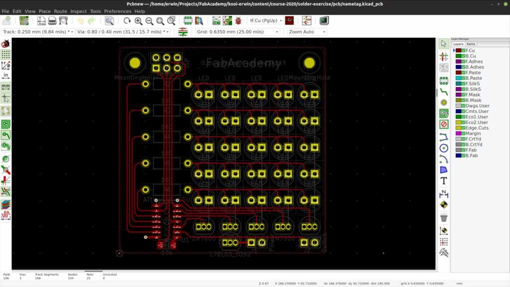
The KiCAD project file can be found here.
The KiCAD schematics file can be found here.
The KiCAD pcb file can be found here.
The source code main.c file can be found here.
The source code main.h file can be found here.
The source code font.h file can be found here.
- The voltage regulator was soldered in reverse. This made it very hot very quickly. I fixed this by removing the regulator after cooling my fingers under the running tap for at least 5 minutes…
- Clear LEDs are great for a head-on view, but not so great for an angled view.
- Not much. I would use diffuse LEDs.