 Erwin Kooi
Master mind
This puzzle is based on the game of Mastermind.
Get four digits in the correct position.
A code is generated each time the game is powered on.
The player enters four digits using BCD (Binary Coded Decimal) wheels. After setting these numbers, the player presses “Enter” and the four LEDs will indicate if the digit is correct and in the right place (green), correct but in the wrong place (red) or wrong (off). If all LEDs are green, the puzzle is solved.
  graph LR
    BEGIN(INIT) -- receive solution --> A2[READY]
    A2-- receive start -->A3[RUNNING]
    A3-- button pressed --> A4[Read next BCD wheel]
    A4-->Q1{Check solution}
      Q1-- number correct -->A5[Increase counter]
      A5-->Q2{Last BCD wheel}
        Q2-- yes -->A7
        Q2-- no -->A4
      Q1-- position correct -->A6[Increase counter]
      A6-->Q2
    A7[Update LEDs]-->Q3{all positions correct}
      Q3-- yes -->END(END)
      Q3-- no -->A3
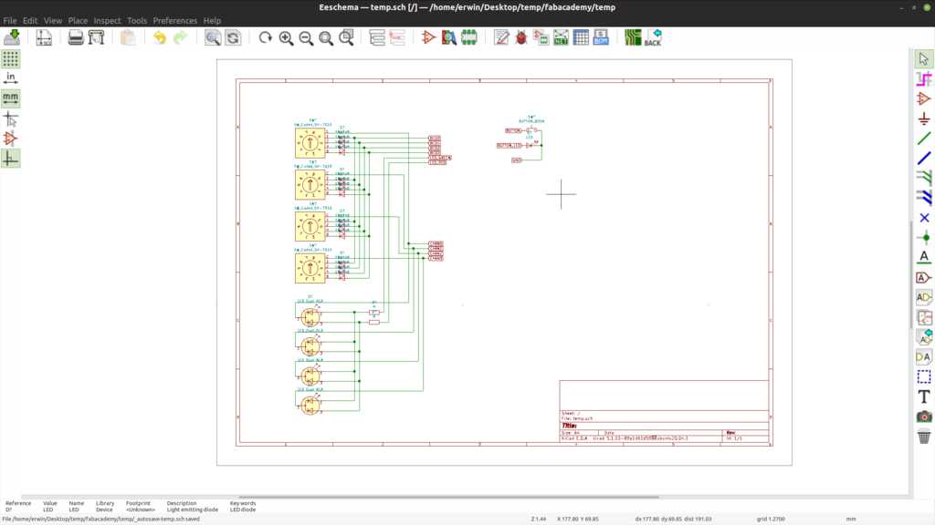
The BCD wheels have a 4-bit output each. This would require 16 I/O pins if we connect all wheels individually. We can however multiplex the signals, so we only need 4 bits for addressing and 4 bits for input. The 4 address bits can even be brought down to 2 if we use a multiplexer, but 8 bits in total is a nice round number. :-)
Note that the input lines of the wheels are all connected together. This can cause unwanted mixing of signals, so each line needs a diode to prevent unwanted voltages of unselected wheels to reach the input pins.
The LEDs are bi-color LEDs which have three pins. One for the red anode, one for the green anode and one common cathode. This would require 8 I/O pins in total if we connect all LEDs individually. Just like the BCD wheels, we can multiplex the signals and use persistence of vision when strobing the LEDs. This will make them appear lit al the time, even when we are strobing them at a high enough frequency. This will require 6 bits.
The Enter button requires 1 bit.
The button LED requires 1 bit.
In total, we need 12 I/O pins in the microprocessor. An Atmega328p wiil fit nicely and will also provide serial communication to the overall puzzlebox controller.
4 x BCD code wheel (“common cathode”)
16 x 1n4148 diode (4 per BCD wheel)
1 x button (square green with LED)
4 x duo LED 5mm common cathode
1 x resistor 330 Ohm
1 x resistor 330 Ohm
1 x PCB
1 x Attiny3216
1 x MAX485
1 x 1206 resistor 0 Ohm
1 x 1206 resistor 330 Ohm
1 x 1206 capacitor i uF
1 x 1206 LED (red)
2 x 01x02 pinheader SMD (for UPDI, switch)
2 x 01x04 pinheader SMD (for serial and channel)
1 x 01x07 pinheader SMD (for BCD wheels and LEDs)
1 x 02x03 pinheader SMD (for RS485)


The PCB can be found here:
The code can be found here: