 Erwin Kooi
04 - Electronics Production
This week focusses on electronics and Printed Circuit Board (PCB) production. Instead of sending designs to a big PCB farm, the focus is on milling them with a CNC.
The project this week is to build your own In System Programmer (ISP). I already have a bunch of these, including the AVR Dragon.
But since the acquisition of Atmel by Microchip, new ATtinys have emerged. They are pretty powerful and rival some of the old ATmega’s. They use a different Universal Programming and Debugging Interface (UPDI) and I am planning to build that one.
The assignments for this week are two-fold:
-
Group assignment
- Characterize the design rules for your PCB production process: document feeds, speeds, plunge rate, depth of cut (traces and outline) and tooling.
- Document your work (in a group or individually)
-
Individual assignment
- Make an in-circuit programmer by milling and stuffing the PCB, test it, then optionally try other PCB fabrication process.
- I have a strong background in electrical engineering, but expect that I will be revisiting a lot of fundamentals this week.
- I work with KiCAD a lot.
- Working with a CHC is new. It is another X/Y tool, but has its own quirks to work on.
- I participated in a group-buy of a desktop CNC machine. This will be great for prototyping. Building the components will help me understand the finer details of CNC tuning.
- Setting up the CNC requires focus and attention for details.
- The CNC is a great tool for building prototype PCB’s before ordering them in batches from a big PCB production facility. This will be very useful for my final project.
The group assignment will get us up to speed with the functioning and operation of the CNC mill. This knowledge will be used to finish the individual assignment, create a microprocessor programmer.
There are quite a number of different ways of programming a microcontroller, depending on the brand, type and age.
In the old days… microprocessors (like the Intel 80C196KC I worked on in 1995) did not have program memory and a separate EPROM had to be used. Programming required a ZIF socket and an UV lamp for erasing.
Nowadays microprocessors have lots of internal program memory and can be programmed while they remain embedded in the circuit. Programming is done via an ISP (In System Programmer), JTAG (Joint Test Action Group) or Universal Programmer and Debugger Interface (UPDI).
This week I will be making a UPDI.
PCB’s are typically created with FR4 (glass fiber) boards.
The machine at the lab is an MDX-20 and has a step-accuracy of 0.006 mm. That is 6 microns. o_O
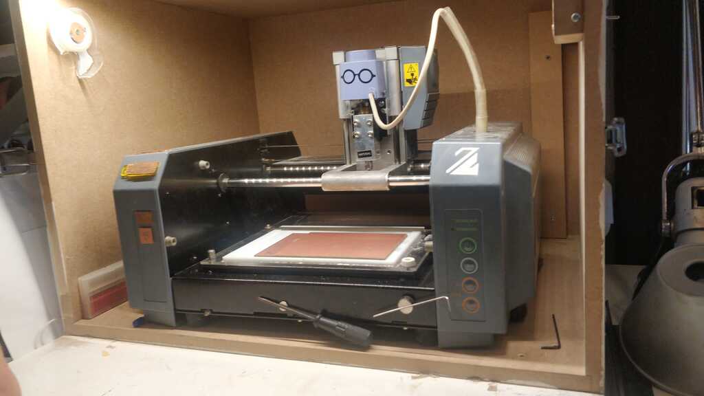
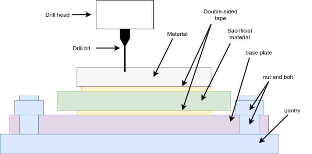 The material to be milled must be placed carefully on a number of layers.
First on top a a sacrifical layer using double-sided tape. This sacrificial layer will protect the lower layers if the mill bit will go through the material.
Then on top of a solid build plate using (you guessed it) double-sided tape. This build plate will give stiffness to the layers and will make sure the material remains flat.
Finally on top of the machine's gantry using nuts and bolts. The bolts must be tigntened equally, so the material is flat.
The material to be milled must be placed carefully on a number of layers.
First on top a a sacrifical layer using double-sided tape. This sacrificial layer will protect the lower layers if the mill bit will go through the material.
Then on top of a solid build plate using (you guessed it) double-sided tape. This build plate will give stiffness to the layers and will make sure the material remains flat.
Finally on top of the machine's gantry using nuts and bolts. The bolts must be tigntened equally, so the material is flat.
Warning
Make sure not to overlap the double-sided tape, as this will cause unevenness in the stack.
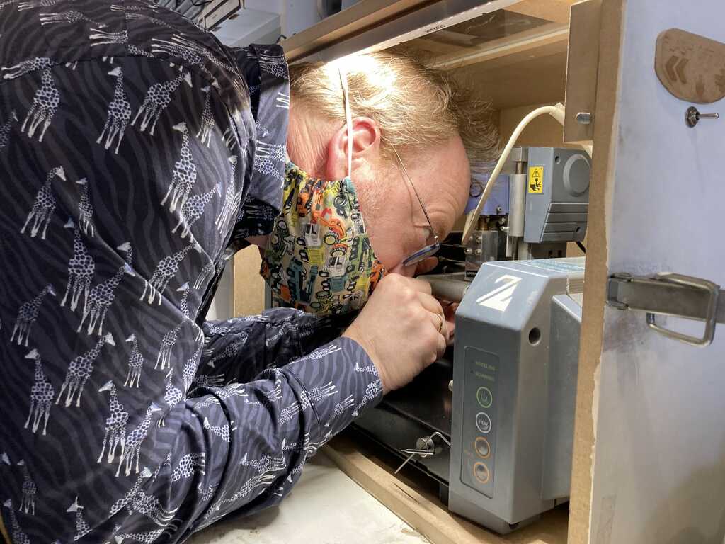
Placing the mill bit is done in a specific sequence:
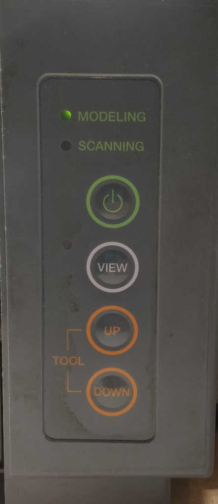
- Press the “View” button will move the head and gantry to a position where the mill bit can be accessed.
- Raise the head using the buttons on the machine
- Open the mill bit holder with the allen key in the green grub nut
- Insert the mill bit very high up in the head
- If the LED on the “View” button is lit, press it to bring the machine to a ready state
- Move the head to the position that you want to cut using the software by entering the numbers into the “Origin” section.
- Lower the head all the way down using the buttons on the machine
- Raise the head a little bit again (3mm) using the buttons on the machine
- Open the green nut and gently lower the mill bit onto the surface
- Tighten the green nut while lightly pushing the bit down on the surface
The machine is now ready to operate and will remember the Z-position of the head as the zero-position.
Hint
Record the X and Y origin as set in the software. We will need these numbers after we change the mill bit.
The software for operation is MODS.
For this particular cnc mill, a workflow is defined with sensible defaults. The machine is connected through the serialserver.js module, not the serialserver.py module.
For milling traces, the presets are:
- Load a file (black areas will be milled)
- Load the 1/64 inch presets
- tool diameter 0.4 mm
- cut depth 0.003 inch
- max cut depth 0.003 inch
- speed 1 mm/s
- 4 traces
- offset stepover .5
- direction Climb
- path merge 1
- Record the X/Y origin coordinates
- Calculate the toolpath
- Check the tool path
- Send the file to the mill
Warning
Do not forget to insert the correct mill bit into the machine before sending the file to the mill.
For milling outlines, the presets are:
- Load a file (black areas will be milled)
- Load the 1/32 inch presets
- tool diameter 0.8 mm
- cut depth 0.5 mm
- max cut depth 1.55 mm
- speed 4 mm/s
- 1 trace
- offset stepover .5
- direction Climb
- path merge 1
- Check the recorded origin X/Y coordinates
- Calculate the toolpath
- Check the tool path
- Send the file to the mill
Warning
Do not forget to insert the correct mill bit into the machine before sending the file to the mill.
Resetting the machine
When a file is sent to the machine, it is in its memory and processed from there. The software has no longer control over it. If an error occurs, the file has to be flushed from the mill.
- press “View” (the machine will pause)
- press “Up” and “Down” simultaneously for 10 seconds (the machine will clear its memory)
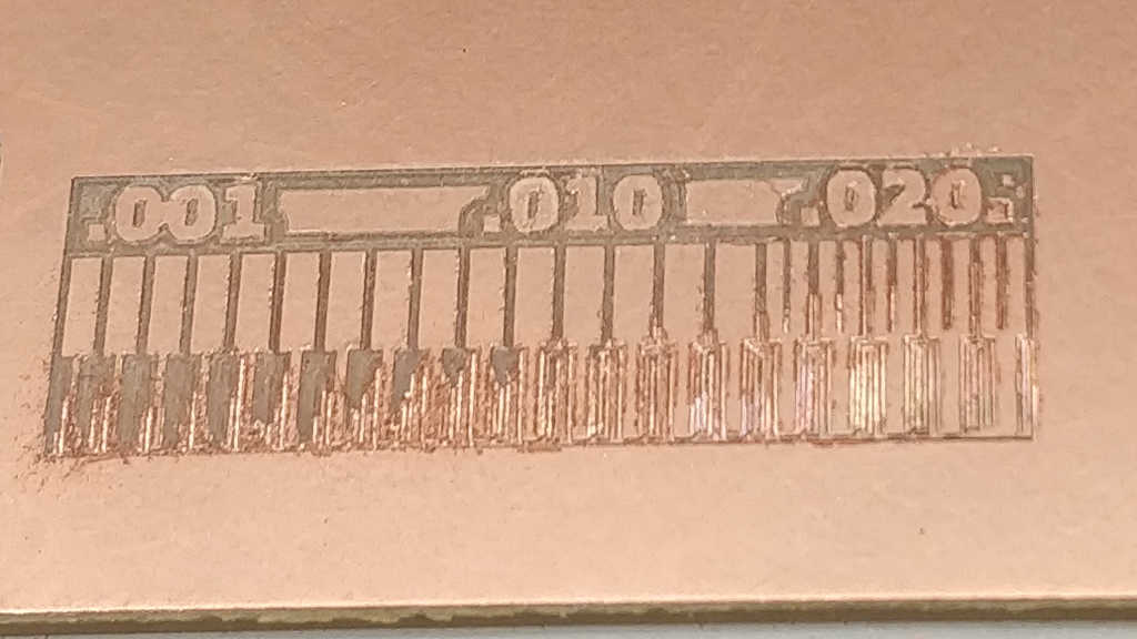
The group assignment is to make measurements to determine the smallest slot and smallest trace the mill can produce. This depends on a number of variables, like step size and mill bit diameter.
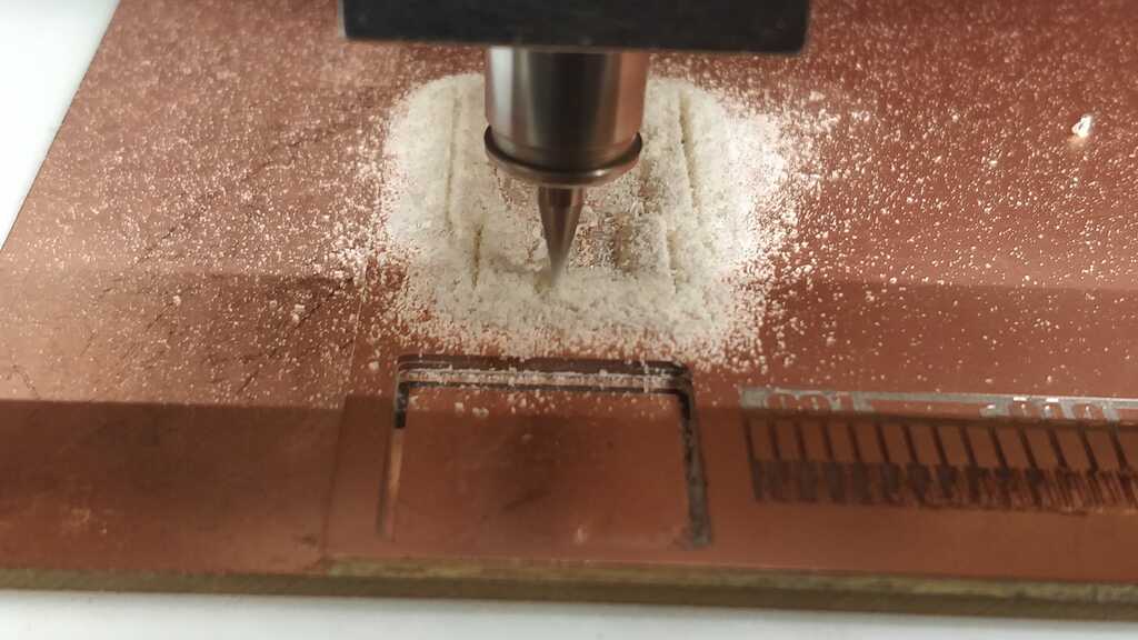
On the first try, the heapng went all the way to the top and started milling in the air. Turns out we used the software to adjust the Z-axis and that does not affect the Z-calibration of the mill. It will simply lower the head, but remember that its zero-point was all the way at the top.
After using the buttons on the machine, this was fixed and we could continue to our second try.
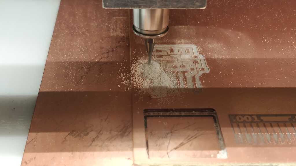
On the second try, the machine started milling, but it was very uneven.
On the left side there is still copper where there shouldn’t be any. Turns out that tightening the green nut will slightly raise the mill bit a few microns. Enough to give an uneven result.
After re-inserting the mill bit and lightly pushing it down on the material while tightening the green nut, we could continue to our third try.
On the third try, we had success.
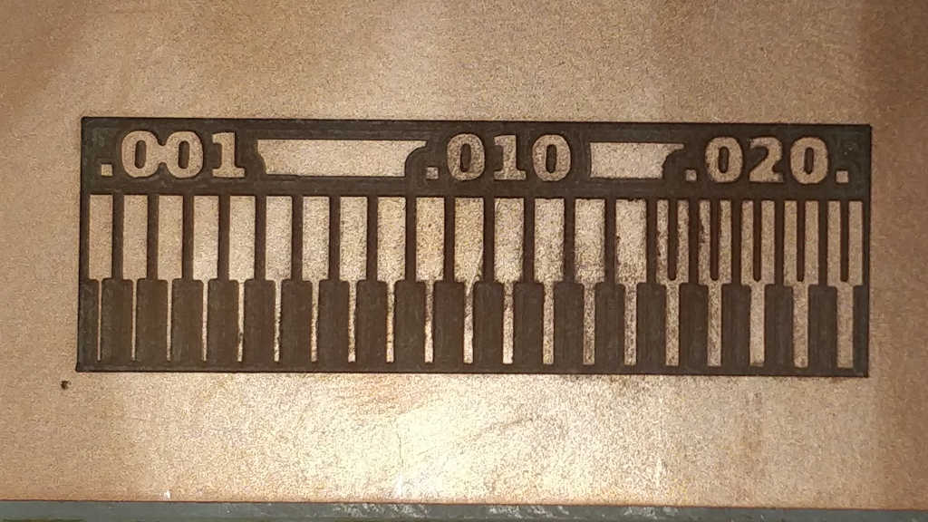
This looks as expected. We then proceeded to change the mill bit to mill an outline and remove the board.
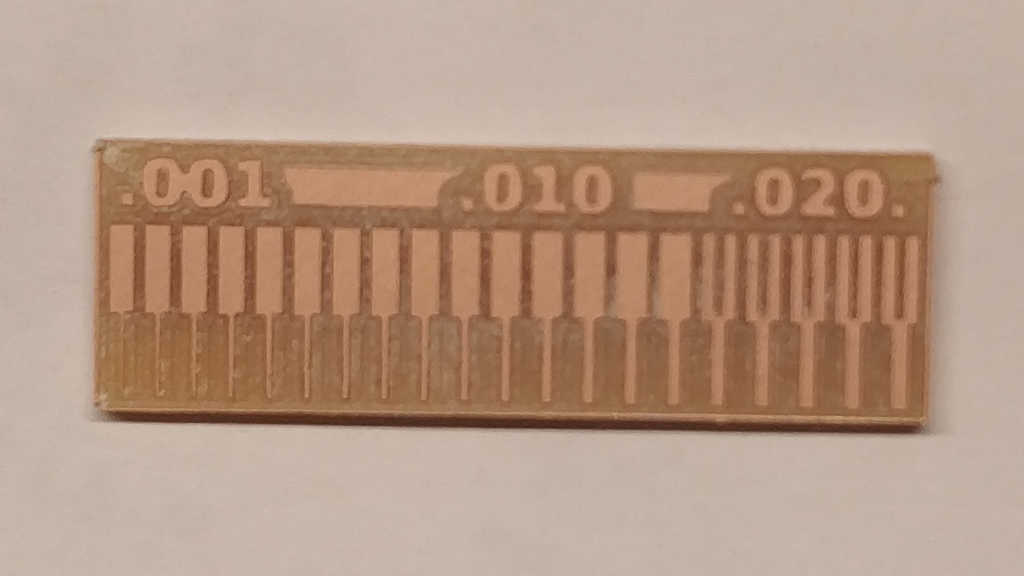
This shows that the mill is capable of leaving traces of .001 inch (0.0025 mm) and slots of 0.16 inch (0.4 mm). Turns out that the software is using the entered mill bit diameter and not bothering milling slots that would be smaller than the mill bit.
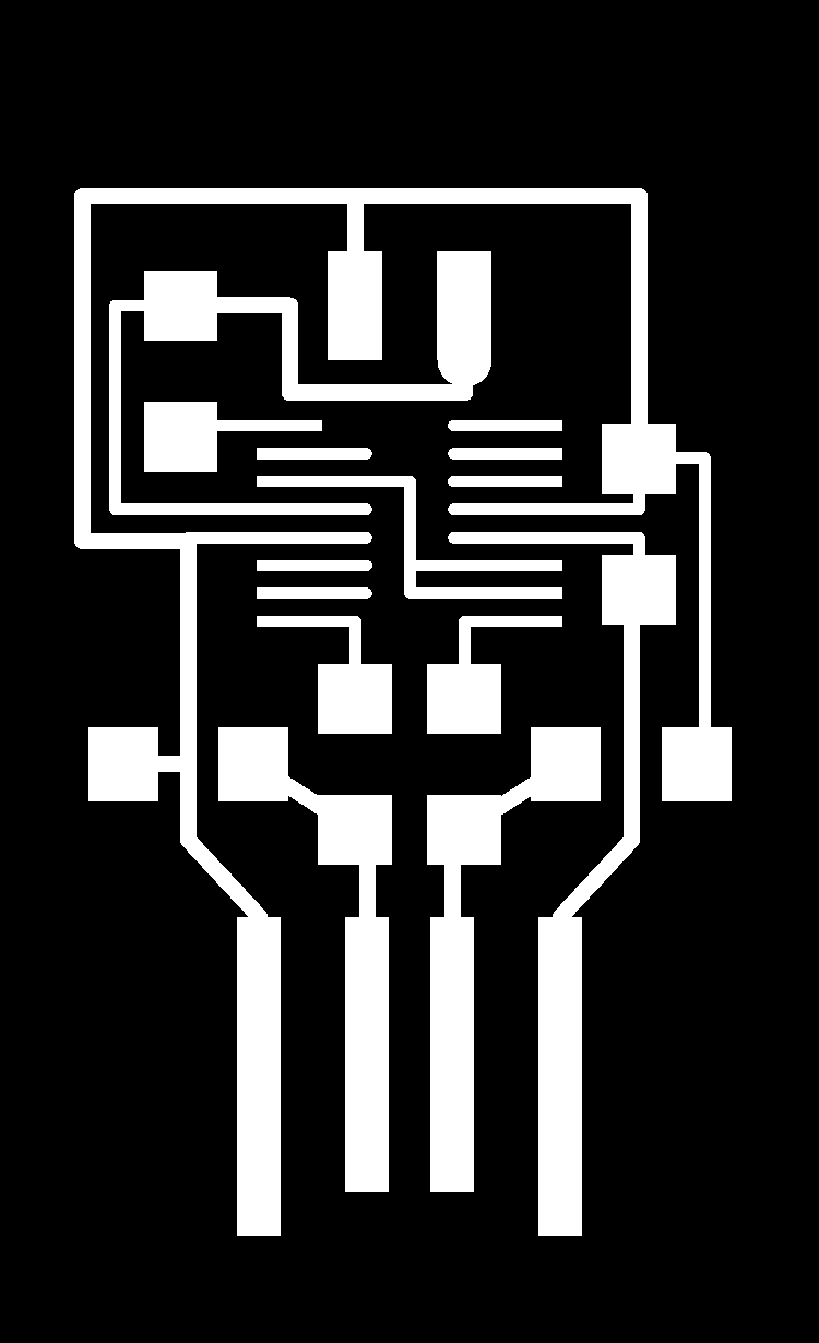
The files for the UPDI programmer are provided by FabAcademy. It is wise to mill the traces first and then cut the outline. After changing to the correct bit for traces and loading the presets, off we went:
This looks fine, so after changing the bit for the outline and loading the presets, off we went again:
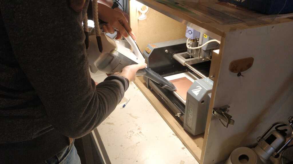
And don’t forget to vacuum after the mill is done…
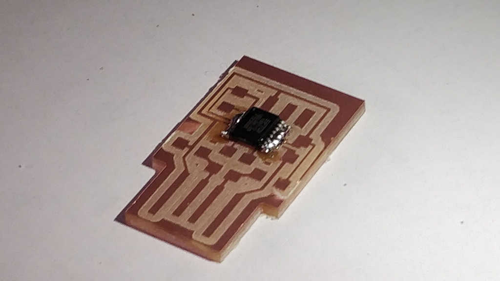
The IC on the board has a .1 inch spacing between the legs. This is a good example where drag-soldering can help (if you do not have a wave-solder station or a smd stencil with solder paste and a smd oven).
Since solder loves to stick to traces and component feet, but not to the FR1 board material,we can put a glob of solder on the pins. Then re-heating the solder and sucking away the excess solder will leave a perfectly soldered component.
The other components are soldered by first applying solder to one pad on the pcb, putting the component on top, reheating it and let the component sink into the solder. Then the other side of the component can be soldered to the pcb, while the first solder connection will keep the component in place.
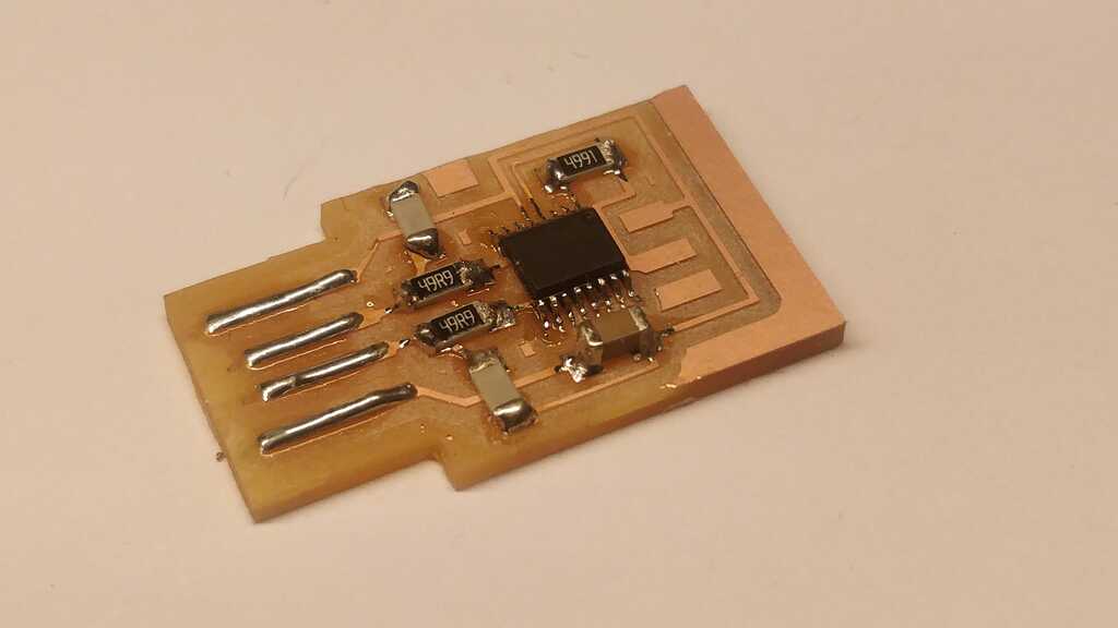
The copper at the edge was removed using a sharp knife, otherwise it would short the USB port. Since my USB port is very well used, I added a bit of solder to the USB traces so they will make better contact to the springs inside the USB port.
To test the programmer, I inserted it into a computer and recorded the syslog output.
After inserting:
kernel: usb 1-2: new full-speed USB device number 23 using xhci_hcd
kernel: usb 1-2: New USB device found, idVendor=0403, idProduct=6015, bcdDevice=10.00
kernel: usb 1-2: New USB device strings: Mfr=1, Product=2, SerialNumber=3
kernel: usb 1-2: Product: FT230X Basic UART
kernel: usb 1-2: Manufacturer: FTDI
kernel: usb 1-2: SerialNumber: D308HTPS
kernel: ftdi_sio 1-2:1.0: FTDI USB Serial Device converter detected
kernel: usb 1-2: Detected FT-X
kernel: usb 1-2: FTDI USB Serial Device converter now attached to ttyUSB0
After removing:
kernel: usb 1-2: USB disconnect, device number 23
kernel: ftdi_sio ttyUSB0: FTDI USB Serial Device converter now disconnected from ttyUSB0
kernel: ftdi_sio 1-2:1.0: device disconnected
The programmer is successfully identified as a FTDI serial converter and attached to a tty port on my computer.
Unfortunately, the connectors for attaching it to a UPDI microprocessor were not available. This will be corrected in one of the following weeks.
Traces can be found here.
Board outline can be found here.
- The operating of MODS went fine. I installed it also on my computer.
- The setup of the cnc mill was very precise. We managed to have the mill bit disappear into the head, over-tighten the green nut (so it became almost unreachable), drop the mill bit into the machine and mis-align the Z-axis so the mill started milling into the air. By retracing our steps and discussing them with the Node instructor, we managed to fix them.
- Not much. It was a very instructive week.
- I would add a VCC pin to the UPDI programming header with a jumper to enable/disable it. This will allow powering of a board-under-test with only the UPDI.
- I will update this site to move all machines in a dedicated section where I can document the required setup. This will make it much easier to find the steps quickly again.
Control is also done using MODS. Not by selecting a machine, but by selecting the g-code generator for 2D pcb.