 Erwin Kooi
12 - Output devices
This week is all about motors, lights and displays! Yay! A vital part of a control loop.
-
Group assignment:
- Measure the power consumption of an output device
- Document your work (in a group or individually)
-
Individual assignment:
- Add an output device to a microcontroller board you’ve designed and program it to do something
- I already know how to add a display to a microcontroller using i2c or spi
- Can I fit the code in an attiny?
As a group we were interested in measuring the power needed to drive a motor and to see the noise it generates on the VCC line.
The voltage drop (potential difference to be precise) across a component can be measured with a Volt meter. This is a meter that will be connected parallel to the device.
The current through a component can be measured with an Ampere meter. This is a meter that will be connected in series with the device. This meter is also a volt meter that measures the voltage drop over a very small known resistor. Using Ohm’s law I = V / R, the current can be calculated.
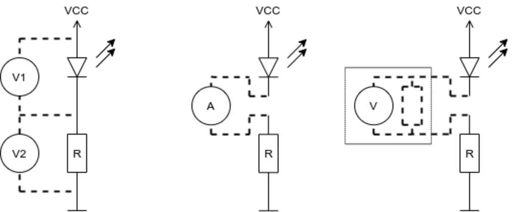
Instead of the LED in the diagram above, we will measure motors.
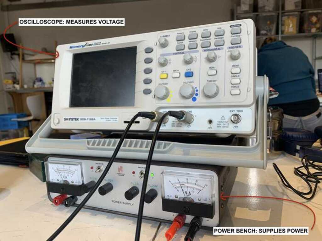
We created a test-setup with a power supply, an oscilloscope and multi-meter.
(I am still somewhat proud of the power supply, as it was a project from my BSEE in 1994 and it has never failed me.)
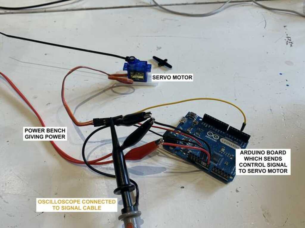
First we attached a servo to a pwm pin of an Arduino and wrote a little sketch.
#define PIN_PWM 5

void setup() {
  pinMode(PIN_PWM, OUTPUT);
}

void loop() {
  analogWrite(PIN_PWM, 0);
  delay(1000);
  analogWrite(PIN_PWM, 127);
  delay(1000);
  analogWrite(PIN_PWM, 0);
  delay(1000);
  analogWrite(PIN_PWM, 255);
  delay(1000);
}
This will move the servo to the left, wait a second, move the servo half-way, wait a second, move the servo to the left, wait a second and finally move the servo all the way to the right (and wait a second before starting over).
Using the oscilloscope we determined the correct PWM signals were generated. However, the servo’s we connected reacted in strange ways. It sounded like the gear-box/position sensor was not aligned with the output shaft. We were able to measure the (1 second) noise that was generated on the VCC line of the motor.
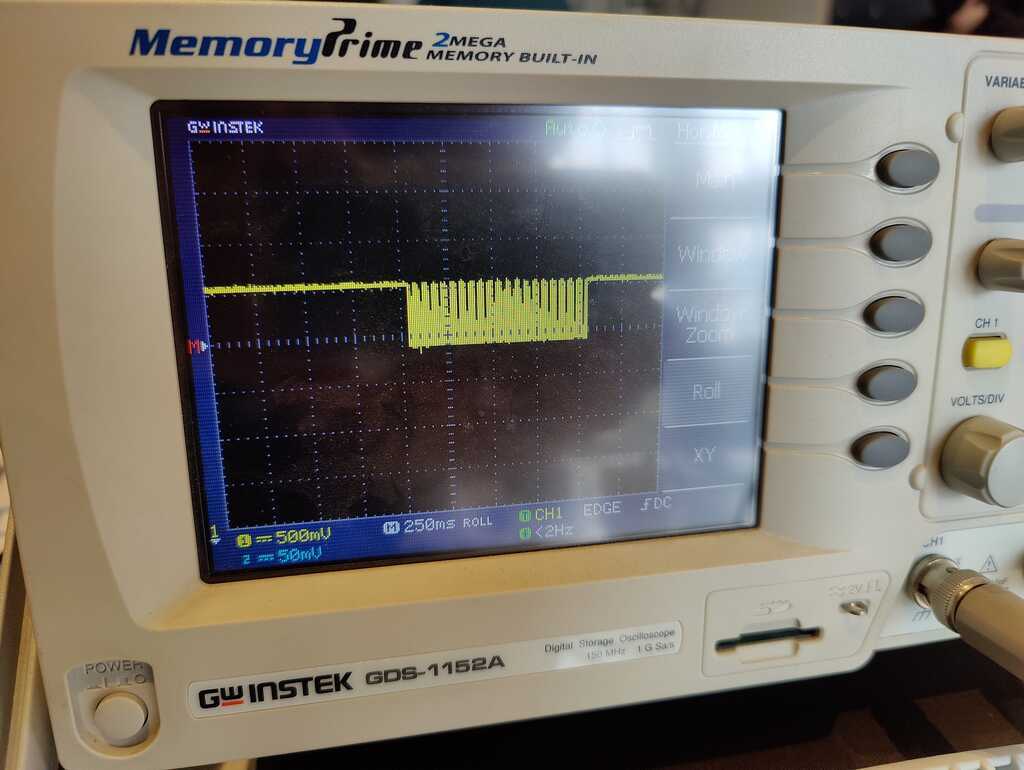
The noise is 0.5 volt in the frequency of the pwm signal. Looking at the signal, there are 20 spikes in one second, which translate to a frequency of 20 Hz. A smoothing capacitor can greatly reduce this noise by acting as a low-pass filter.
Then we proceeded to measure DC motors.
We set the power supply to 5 Volt and measured the current draw. This was around 120 mA.
Measuing the voltage, we noticed that it had dropped to 4.85 Volt. This means that there is a drop of 150 mV across the motor. The DC motor is basically a big coil inside, so this will give a resistance of 1.25 Ohm.
This was with a free-running motor. Applying a force on the rotor shaft, raised the current draw quickly to 600 mA as more power was needed to spin the shaft.
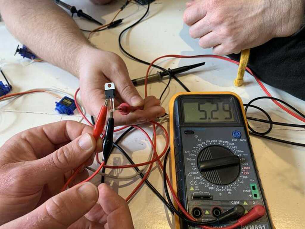
We also measured a 7805 voltage regulator to see its response to various supply voltages.
It is capable of supplying a steady 5 Volt and 1.5 Ampere from an input voltage up till 30 Volt.
It turns out that the 7805 requires at least 1V to operate, so supplying 6 Volt or higher will let it provide the steady 5 Volt output.
If more volts are supplied, they need to be dropped. Supplying 9 Volt means that 3 Volt needs to be dropped. This will be done by heat. Therefor, the 7805 can be attached to a heat sink. If we take the maximum specs (30 Volt and 1.5 Ampere), this means that 24 Volt * 1.5 Ampere = 36 Watt needs to be shedded. This can become hot very quickly…
As individual assingment I will add an i2c display to the sensor board of week 10. Please read this week on why it is taking a long time to get it finished… Most of the work for this week is also done for week 10.
It turns out that I made an error in connecting the SDA and SCL lines to the microcontroller. This was fixed with jumper wires.
The display is a small 0.91 inch OLED display with a ssd1306 controller. This is a very well known and often used controller for this type of displays. The screen itself has 128x32 pixels.
The vl53l0x and ssd1306 display are both connected to the same i2c bus. Because they have different addresses (0x52 and 0x53 for the sensor, 0x3c for the display), there is no conflict when addressing either one of them.
Addressing the display using the Adafruit library is pretty straight forward. Because these libraries are made by one company and made to work together, there is also no conflict between two different methods of communicating with the i2c bus.
Initialize a display-object in your code, give it a few parameters like text-size and of you go.
Contrary to LCD displays, When you want to write multiple lines, you explicitly have to specify which y coordinate the new characters should start.
  display.clearDisplay();       // Clear the screen
  display.setCursor(0,0);       // Set the cursor to top-left
  display.print("Distance:");
  display.setCursor(0,16);      // Set the cursor to halfway-left
  display.print(measure.RangeMilliMeter);
  display.print(" mm");
  display.display();            // Update the pixels on the display
Note
Do not forget to call the.display()function after writing information to the display. This function will make sure something appears on the screen itself instead of just in its buffer.
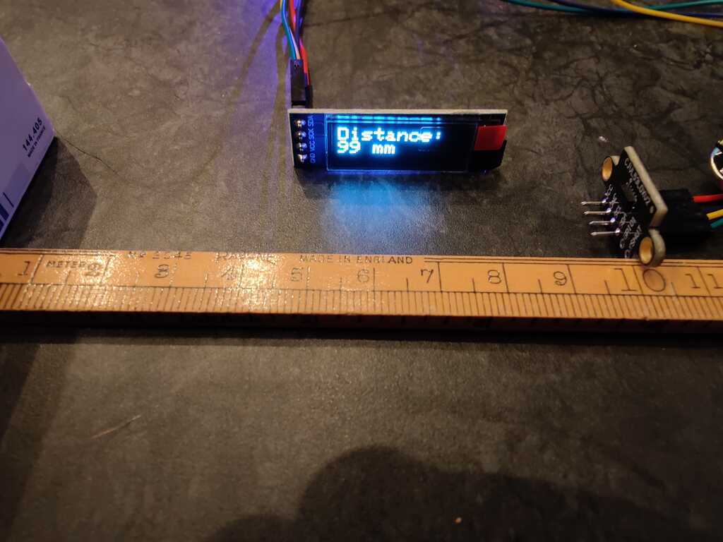
The sensor is pretty accurate. Holding the PCB at exactly 100 mm gives a value of 99 mm. This is because the sensor is 1mm thick and the measuring surface is at 99 mm when the PCB is at 100 mm.
The software is pretty straight forward and leans heavily on the code written in week 10.
  graph LR
    BEGIN([Initialize])-->A1[Read sensor]
    A1-->A2[Update LEDs]
    A2-->A3[Update Display]
    A3-->A4[Update Serial]
    A4-->A5[Delay]
    A5-->A1
// Declare a global display object
Adafruit_SSD1306 display(SCREEN_WIDTH, SCREEN_HEIGHT, &Wire, OLED_RESET);

void setup() {
  // Other code removed for clarity
  if(!display.begin(SSD1306_SWITCHCAPVCC, SCREEN_ADDRESS)) {
    Serial.println("SSD1306 allocation failed");
    while(1); // Don't proceed, loop forever
  }
  display.display();
  delay(2000);                  // Wait for the display to settle

  display.clearDisplay();       // Clear the screen
  display.setTextSize(2);       // Increase text size
  display.setTextColor(SSD1306_WHITE);
  // Other code removed for clarity
}

void loop() {
  // Other code removed for clarity
  display.clearDisplay();       // Clear the screen
  display.setCursor(0,0);       // Set the cursor to top-left
  display.print("Distance:");
  display.setCursor(0,16);      // Set the cursor to halfway-left
  display.print(measure.RangeMilliMeter);
  display.print(" mm");
  display.display();            // Update the pixels on the display
  // Other code removed for clarity
}
Moving the sensor closer to an object shows the different LEDs lighting up and the display showing the value in millimeters.
The source code can be found here.
…
- Measuring output devices is very well possible with a multi-meter as long as the supplied signal is DC.
- Measuring the motors gave some valuable information for our final projects.
- The servo’s did not function as expected, but this was caused by the gear box.
- The SDA and SCL lines on my new Week 10 board were swapped. This was fixed by using jumper wires.
- Triple-check and compare the labels on the schematics with the pinout in the datasheet of the microcontroller.