 Erwin Kooi
Digital safe lock
This puzzle is based on the rotary combination lock on a safe. *** add picture here ***
Find the four correct numbers and put them in the right order. These numbers can be found in another puzzle.
Rotate the knob till the ammeter displays the correct value, push the button to lock this number. A green led will indicate the successful entry. Then move to the next number. If all numbers are found, the puzzle is solved.
Since Additive production methods must be part of the final project, I opted for a 3d printed knob for the rotary encoder. Not much, granted. :-) The FreeCAD file can be found below.
1 x Ammeter
1 x rotary encoder + knob
4 x duo LED 5mm common cathode
1 x resistor 330 Ohm
1 x resistor 330 Ohm
1 x PCB
1 x Attiny3216
1 x MAX485
1 x 1206 resistor 0 Ohm
1 x 1206 resistor 330 Ohm
1 x 1206 capacitor i uF
1 x 1206 LED (red)
3 x 01x02 pinheader SMD (for UPDI, ammeter and LED)
3 x 01x04 pinheader SMD (for serial, channel and rotary encoder)
1 x 02x03 pinheader SMD (for RS485)
The ammeter will be driven by a PCM signal from the microcontroller. A capacitor will be used to smooth the PCM level into a voltage. This voltage level will drive the needle in ten steps (pointing at 10 digits).

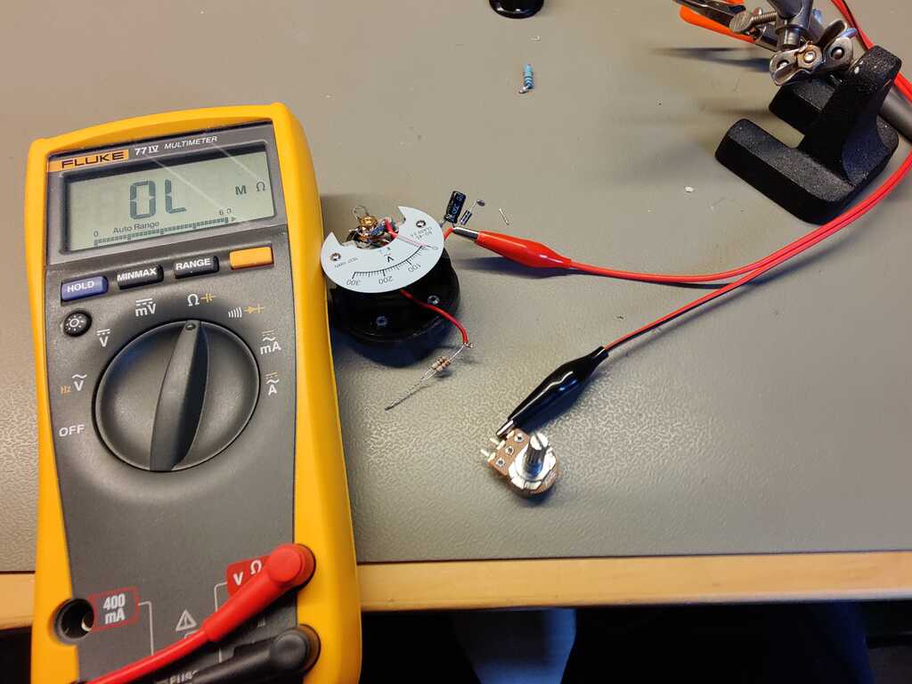
The used meter is for measuring 300V. It uses a resistor of 100k to limit the voltage. This means that a resistor of 100k/300V*5V=1k7 Ohm will give a full swing at 5V. The closes “standard” resistor in the E24 series is a 1k8 Ohm resistor. I also want to use a diode to prevent wrong polarity, so an additional voltage drop of 0.6 has to be accounted for.
I used a 10k potentiometer as resistor and turned the knob till the needle reached its max value. Measuring the potentiometer gave a resistor of 2k4 Ohm. A fixed 2k2 and 220 Ohm resistor in series gives the perfect (2200+220=2420) value.
A smoothing capacitor will be used to remove the ripple from the PCM signal. The value is calculated with the formula
C = I / (2 * f * Vpp)
Where
C = capacitance
I = current (1 mA)
f = frequency (1000 Hz as per attiny3216 data sheet)
Vpp = max allowed voltage drop (the ripple 0.01 V)
This leads to a capacitance of 50 uF (or 47 uF in the E24 scale). There was a capacitor of 47 uF installed. For typical operation, this would lead to 47 uF = 0.001 / (2 * 50 * Vpp), which gives a Vpp of 0.2 Volt (on a 300V scale).


The FreeCAD knob can be found here:
The InkScape panel meter gauge can be found here:
The PCB can be found here:
The code is not available yet.