 Erwin Kooi
03 - Computer-controlled cutting
This week focusses on cutting material using the computer. The primary focus is on laser cutters and vinyl cutters.
The assignments for this week are two-fold:
- As a group
- determine the parameters of your laser cutter like focus, power, speed, rate, kerf, and joint clearance
- Individually
- Design, lasercut, and document a parametric press-fit construction kit, which can be assembled in multiple ways and account for the lasercutter kerf
- Cut something on the vinylcutter
- I have played with the laser cutter at our local hackerspace. This was a heavily customized K40 model. I created some tabbed boxes and engraved cookies.
- I want to work with the vinyl cutter, as this can create intricate designs with sharp edges in paper that are not burned.
- The laser cutter is very powerful. It can handle all kinds of material. Foam inlays will be next on my list. It is great for prototyping. After dialing it in, it is basically fire-and-forget (BUT DO KEEP AN EYE ON IT).
- The vinyl cutter is underrated. It can create very detailed cuts, leaving no marks on the material. It is great for creating beautiful things. The movement of the head is mesmerizing.
- For my final project, I will be using the laser cutter for construction designs, I will be using the vinyl cutter for decoration designs.
- https://cuttle.xyz is a very interesting tool for creating beautiful shapes that can be cut on the laser cutter or the vinyl cutter.
One of the assignments is to create a press-fit construction. Therefor we need to know how much material the laser cutter is removing (the kerf) when cutting and what power and speed setting must be used. The design will have to compensate for this, as a tolerance of 0.1 mm is already too loose.
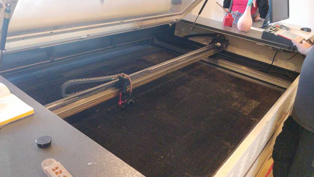
The laser cutter is an old BRM and it is being upgraded and modded. It recently got a Ruida controller and that enables much smoother prints and LightBurn as control software. Awesome!
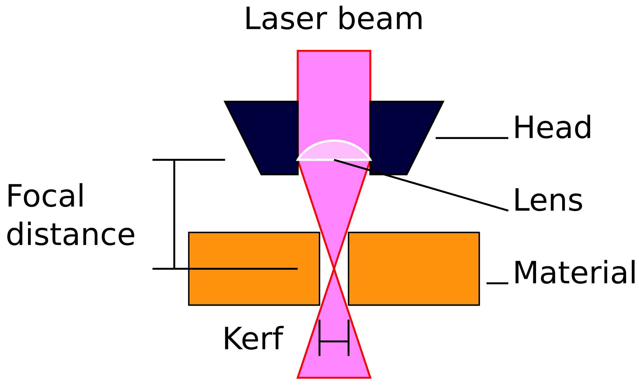 A laser cutter shoots a highly concentrated beam of monochromatic light through a lens that focusses the beam to a single point. At this point, the material is burned away, leaving a hole in the material.
The focal distance is the distance between the lens and the focal point of the laser beam. This point should ideally be placed in the middle of the material, so the focussed beam enters and leaves the material symmetrically. In practice, the focal point is placed at the top of the material and for thin material, this does not matter too much for the asymmetry of the top and bottom. When cutting thick material, this effect should be taken into account and multiple passes with different focal settings should be considered.
The width of the resulting beam is called the kerf. This is a non-zero amount of material that is burned away and must be taken in to consideration when designing for laser cutters.
A laser cutter shoots a highly concentrated beam of monochromatic light through a lens that focusses the beam to a single point. At this point, the material is burned away, leaving a hole in the material.
The focal distance is the distance between the lens and the focal point of the laser beam. This point should ideally be placed in the middle of the material, so the focussed beam enters and leaves the material symmetrically. In practice, the focal point is placed at the top of the material and for thin material, this does not matter too much for the asymmetry of the top and bottom. When cutting thick material, this effect should be taken into account and multiple passes with different focal settings should be considered.
The width of the resulting beam is called the kerf. This is a non-zero amount of material that is burned away and must be taken in to consideration when designing for laser cutters.

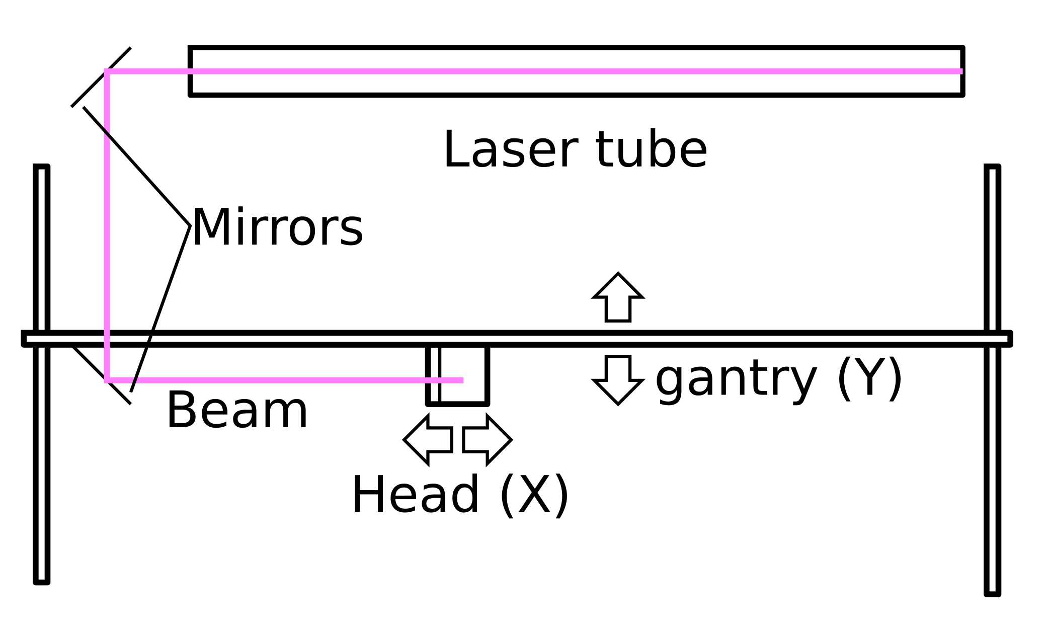 By moving the head in the X/Y plane, the beam is moved in the X/Y plane. Now a line can be cut.
The beam is generated by a laser tube, mounted in the X direction and mirrors reflect and direct the generated beam to the head. The first mirror is stationary and reflects the beam along the Y axis. The second mirror is attached to the gantry and will move with the Y movement of the gantry. It will make sure that the beam is reflected along the X axis to the head. The third mirror is attached to the head and will move with the X movement of the head. It will make sure that the beam is reflected down towards the lens.
By moving the head in the X/Y plane, the beam is moved in the X/Y plane. Now a line can be cut.
The beam is generated by a laser tube, mounted in the X direction and mirrors reflect and direct the generated beam to the head. The first mirror is stationary and reflects the beam along the Y axis. The second mirror is attached to the gantry and will move with the Y movement of the gantry. It will make sure that the beam is reflected along the X axis to the head. The third mirror is attached to the head and will move with the X movement of the head. It will make sure that the beam is reflected down towards the lens.

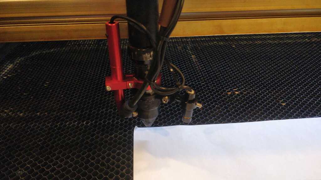
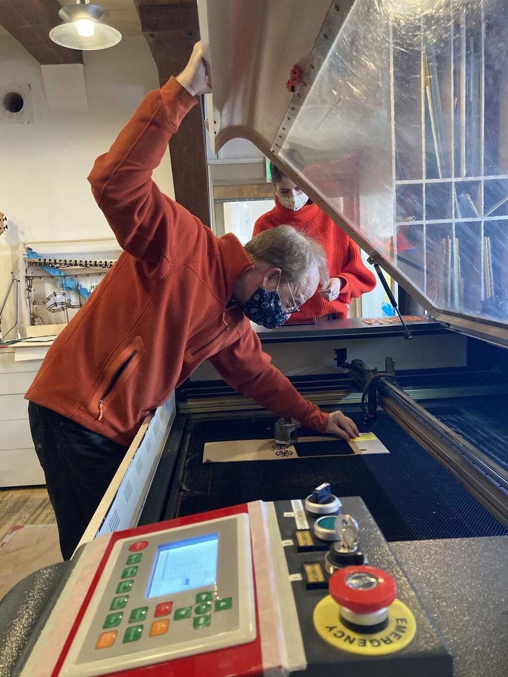
**Safety** The laser is a dangerous machine that will try to set fire to itself (as the FabLab Wapi in the picture found out the hard way (fortunately, nobody was seriously injured)). The laser at the Waag lab is placed on a raised floor. When in operation, there must always be someone at the controls monitoring the machine.
In case of a fire:
- Hit the emergency stop on the machine
- Turn of the extractor fan
- If possible, leave the lid closed to starve the fire from oxygen
For cutting a vector-based design is required, as the head will travel along the path of the vector.
For engraving a raster-based design is required, as the head will put each laser dot on the material like a dot-matrix or inkjet printer.
Inkscape and Gimp are good tools to use.
The laser is controlled by LightBurn. A versatile program specifically for laser controllers. It will optimize the design before sending it to the laser. Like engraving first, then cutting.
The file can be fully prepared and then loaded into LightBurn.
Per layers you can set the speed and power of the laser, so you can tune how much material will be removed. For a cut, you use low speed with high power. For an engraving, you use fast speed with low power.
DO NOT FORGET TO TURN ON THE EXTRACTOR FAN BEFORE TURNING ON THE LASER!
Because the kerf is a sub-millimeter dimension, measuring the kerf can be tricky. A good strategy is cutting nine strips with 10 mm dimension in the CAD software (which will mean 10 cuts), cut them, place them right next to each other and measure the total length. The kerf is then calculated as (designed length - measured length) / number of cuts.
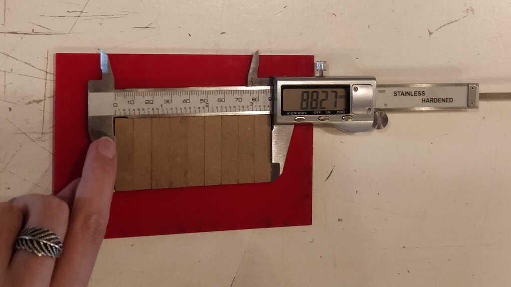
For this laser cutter it is (90.0 - 88.3) / 10 = 0.17 mm. This number will be used in all other designs.
The power of the laser can be controlled using Pulse-Width Modulation (PWM). The total amount of power is equal to the surface under the graph of the PWM signal. By varying the duty-cycle, the amount of power is contolled.
ON__   ____      ____      ____
      |    |    |    |    |    |
OFF_  |    |____|    |____|    |____ Duty Cycle =  50$

ON__   __        __        __
      |  |      |  |      |  |
OFF_  |  |______|  |______|  |______ Duty Cycle =  25%

ON__   _________ _________ _________
      |         |         |
OFF_  |         |         |          Duty Cycle = 100%
The speed also determines the amount of power that is delivered to a single spot. Faster movement delivers lower power to a single spot. Finding a good balance between power and speed is important because
- the time spent on the laser cutter can be minimized
- the details of the cut can be increased
- the burn marks on the material can be minimized
- the risk of burning the project (and the laser cutter) is minimized
If the speed is too high and the power too low, the duty cycle can be seen in the cut as an artefact. Instead of a straight line, the cut will consist of consecutive dots with the diameter of the kerf.
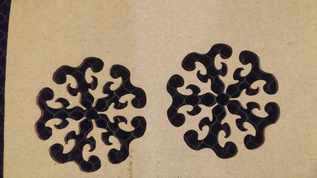
These shapes clearly show the difference in detail on high speed (left) and lower speed (right).
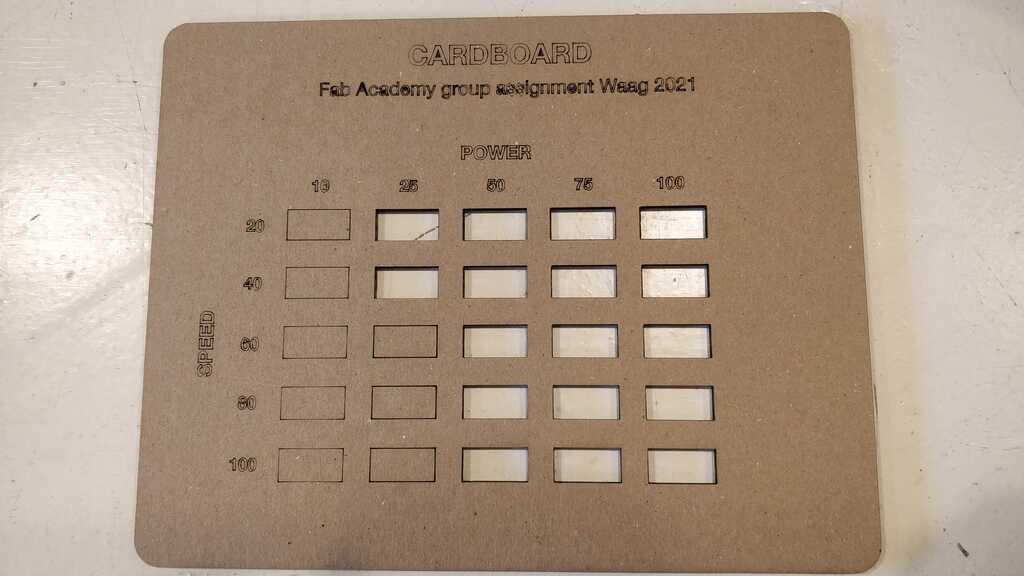
For cutting, power 50 and speed 100 works very well.
The photo for the wood power and speed measurements was corrupted on my phone. o_O
The results were between the settings for cardboard and acrylic.
For cutting, power 75 and speed 80 works very well.
 For cutting, power 75 and speed 40 works very well.
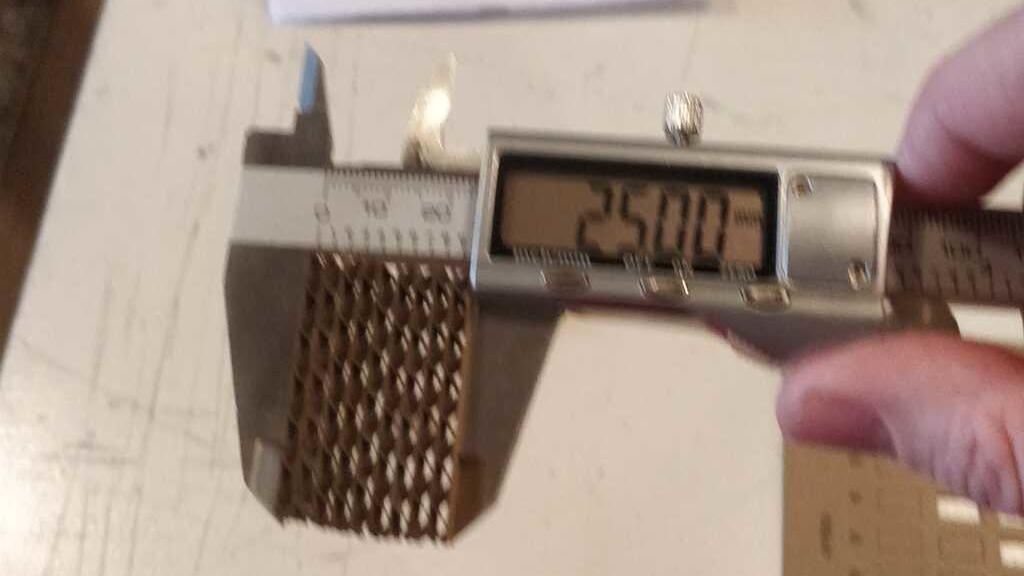
The thickness of the material is also an important factor. This is measured in the same way as the kerf. By stacking the strips, the thickness of the material is calculated by (total thickness)/(number of strips). In this case it is 25 / 9 = 2.8 mm.
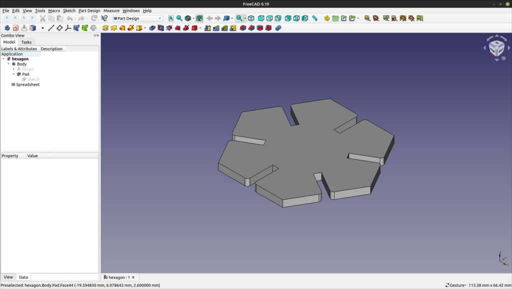
The measurements from the previous chapter will be used to create the press-fit design assignment that will survive the “Henk-test” (vigorous shaking).
I will be creating multiples of this shape, that can be combined in 60 degree angles in a perpendicular plane.
Every dimension of the design is parametric, using the measurements and calculations from the previous chapter.
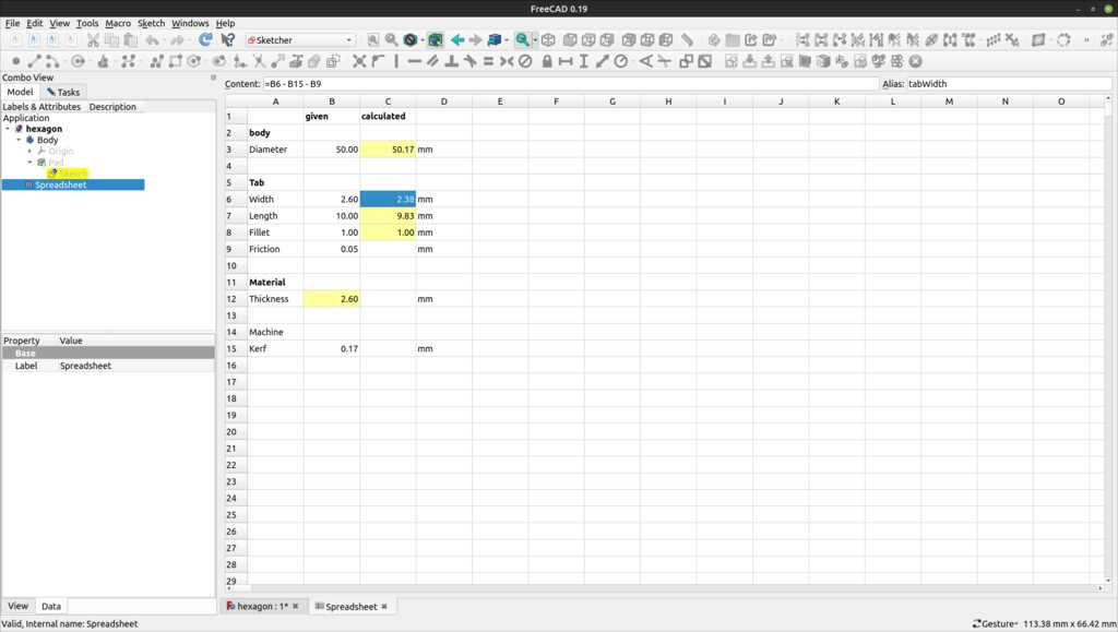
These dimensions are used in the sketch, that is fully constrained.
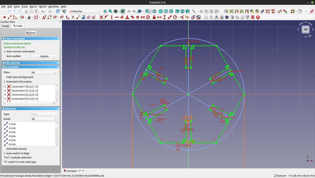
And exported to the laser cutter in a dxf format.
Note
FreeCAD cannot export a single sketch. It has to be converted to a body (eg. by padding it) before it can be exported.
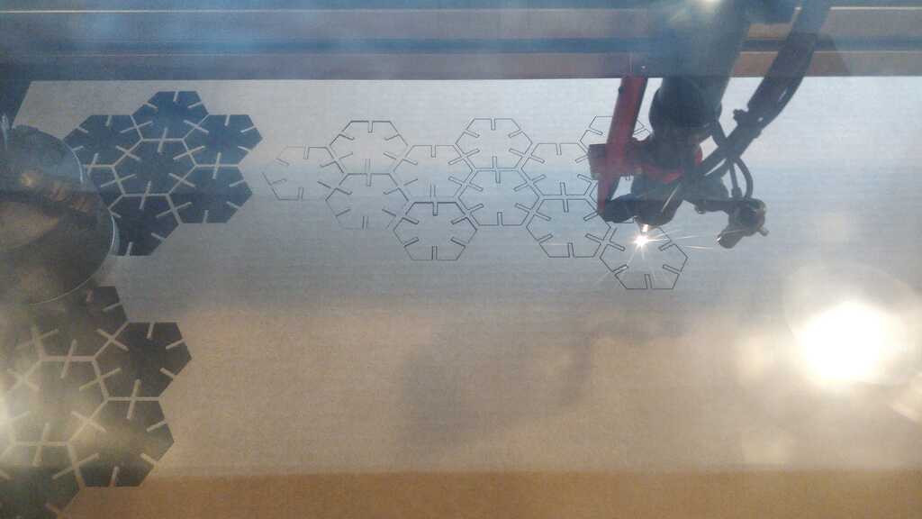
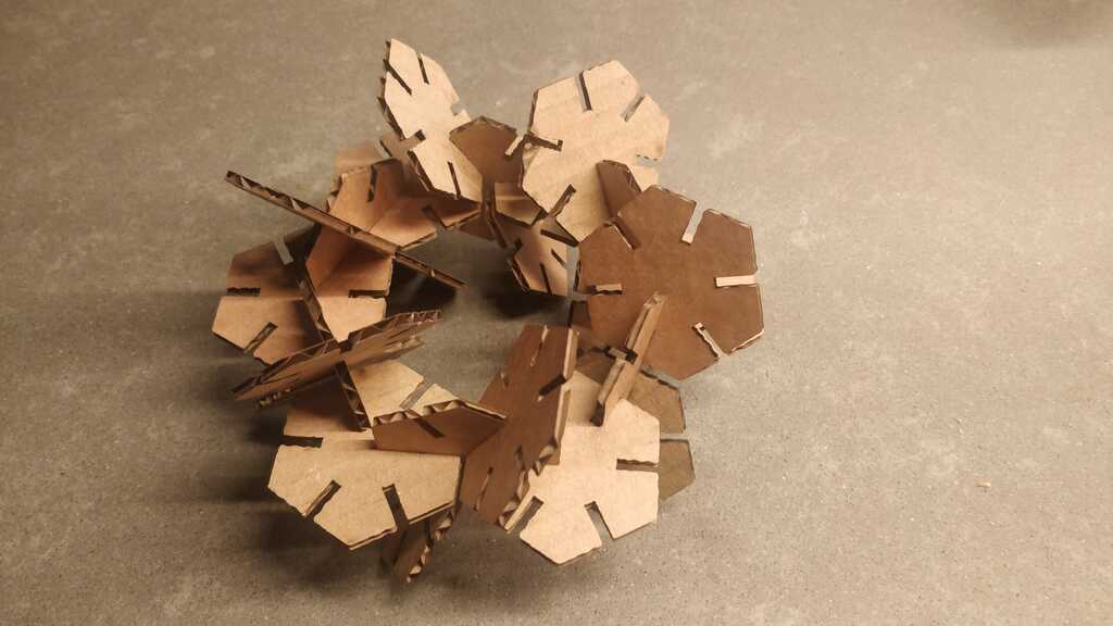
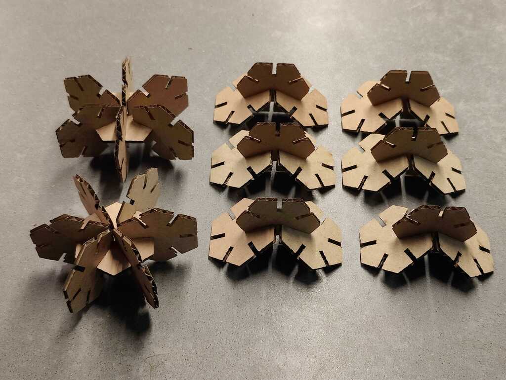
These shapes turned out great and they can be used to construct all kind of fun shapes.
Like a snowflake:
Or a plane:
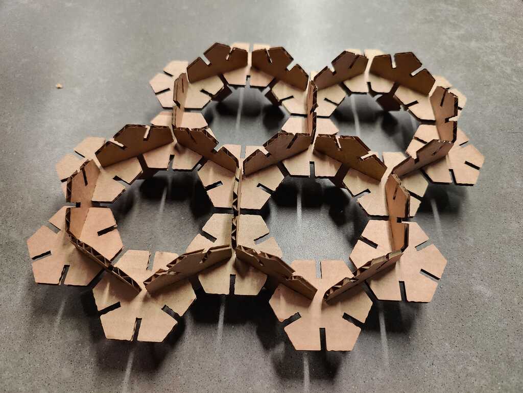
Or a ball (with its components)
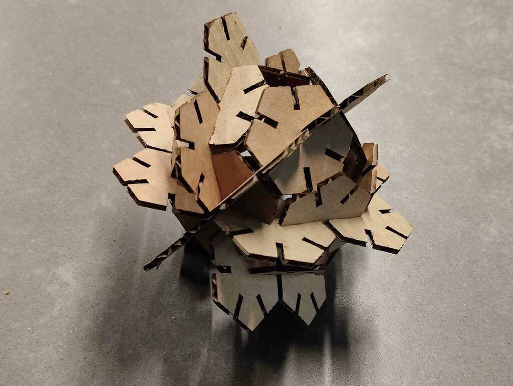
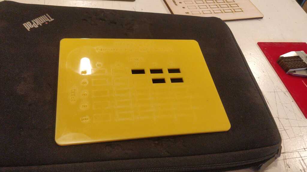
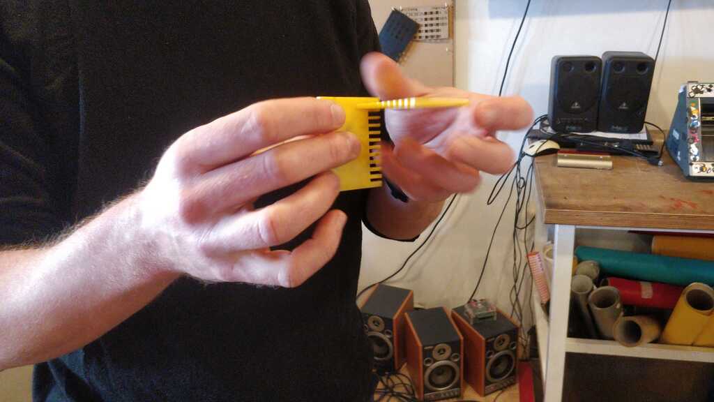
Another way of finding the parameters for a press-fit is creating a design with slots in varying sizes. By fitting them together, you can see which dimension in the CAD tool will work in real life.
The kerf-tool can be found here.
The power-speed-tool can be found here.
The press-fit measuring tool can be found here.
The FreeCAD hexagon can be found here. It survived the Henk-test (vigorous shaking)!
A vinyl cutter drags a sharp knife across a surface. This can be vinyl, vinyl stickers or paper. It can create very delicate cuts without burned edges.
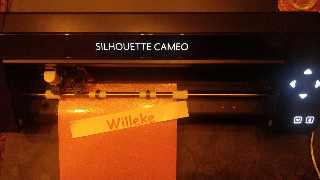
The vinyl cutter is a Roland GS-24 and can be controlled using mods. We had a brief introduction on it. I borrowed a Cameo Sillouette 4 that I will use to experiment with over the weekend.
It is equipped with an auto-blade, a knife that can be adjusted by the machine in height. It can be used to create specific cut-profiles for different types of media.
(Make sure to lock the blade into the holder, otherwise the blade will come loose and not cut.)
For cutting a vector-based design is required, as the knife will travel along the path of the vector.
Inkscape is a good tool to use. FabLab Neurnberg created an Inkscape plugin for this cutter. This allows the cutter to be controlled from within Inkscape.
There are two steps to prepare the cut:
- Path > Object to path (so every line is a vector)
- Extentions > Export > Send to Silhouette…
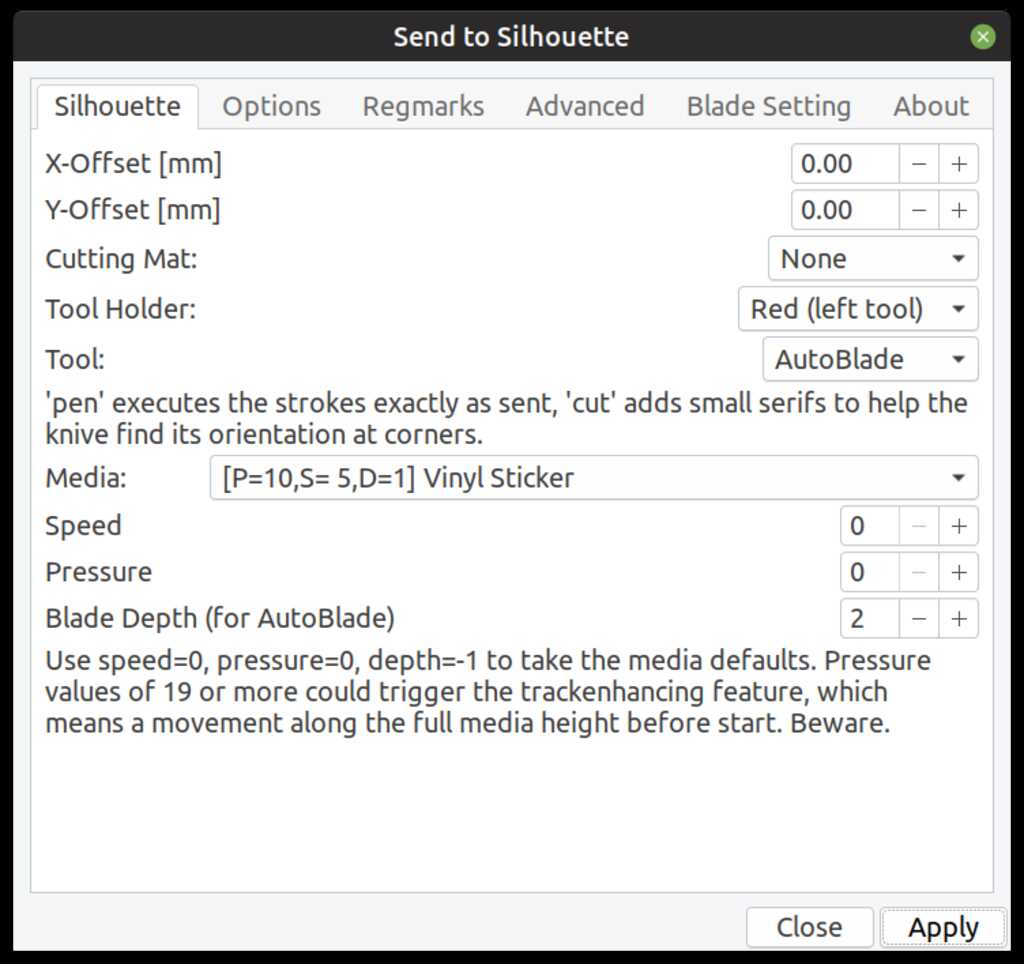
The blade can be set to depths between 0.1 mm and 1.0 mm in steps of 0.1 mm. For most material, this is a bit trial and error.
Vinyl typically has a cover on the back and the vinyl should be cut, not the back (or the cutter itself).
Paper does not have a cover and a cut mat has to be used.
The cutter came with a nice sheet of pink sparkly vinyl sticker (…) A cut of 0.1 mm did not completely cut through the material. A cut of 0.2 mm worked perfectly.
What better thing to cut than a sticker with your wife’s name?…
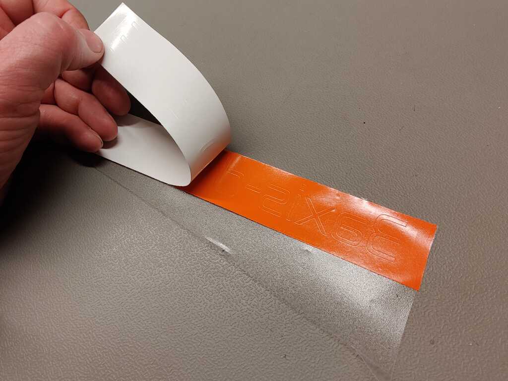
I also created some stickers for the company I am planning to set up. The characters are pretty small, so they need to be weeded from the decal.
First, apply a foil to transfer the cut-but-still-in-the-decal characters to:
![]()
Then remove the paper backing:
Then weed the not-needed material:
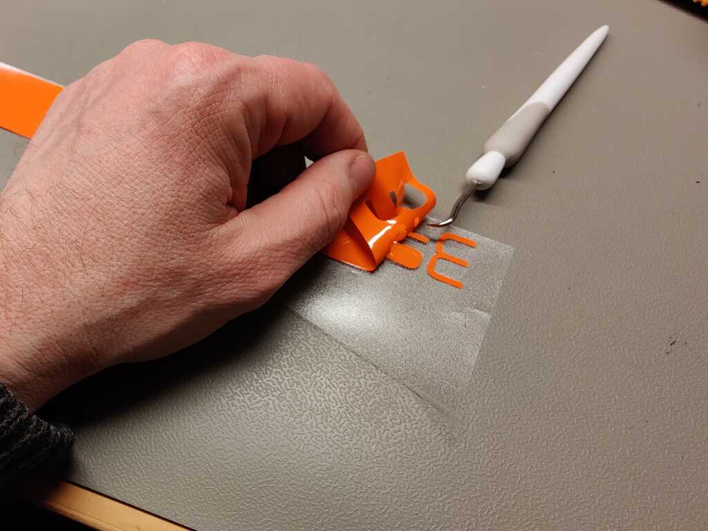
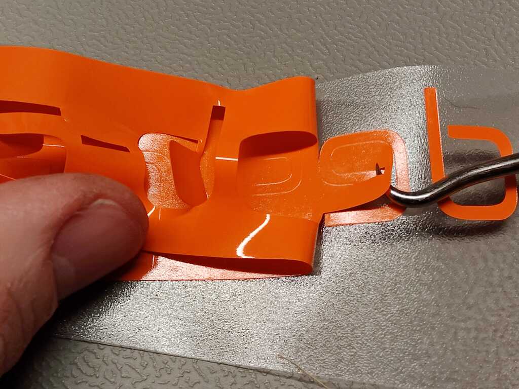
And end up with just the characters on the foil:
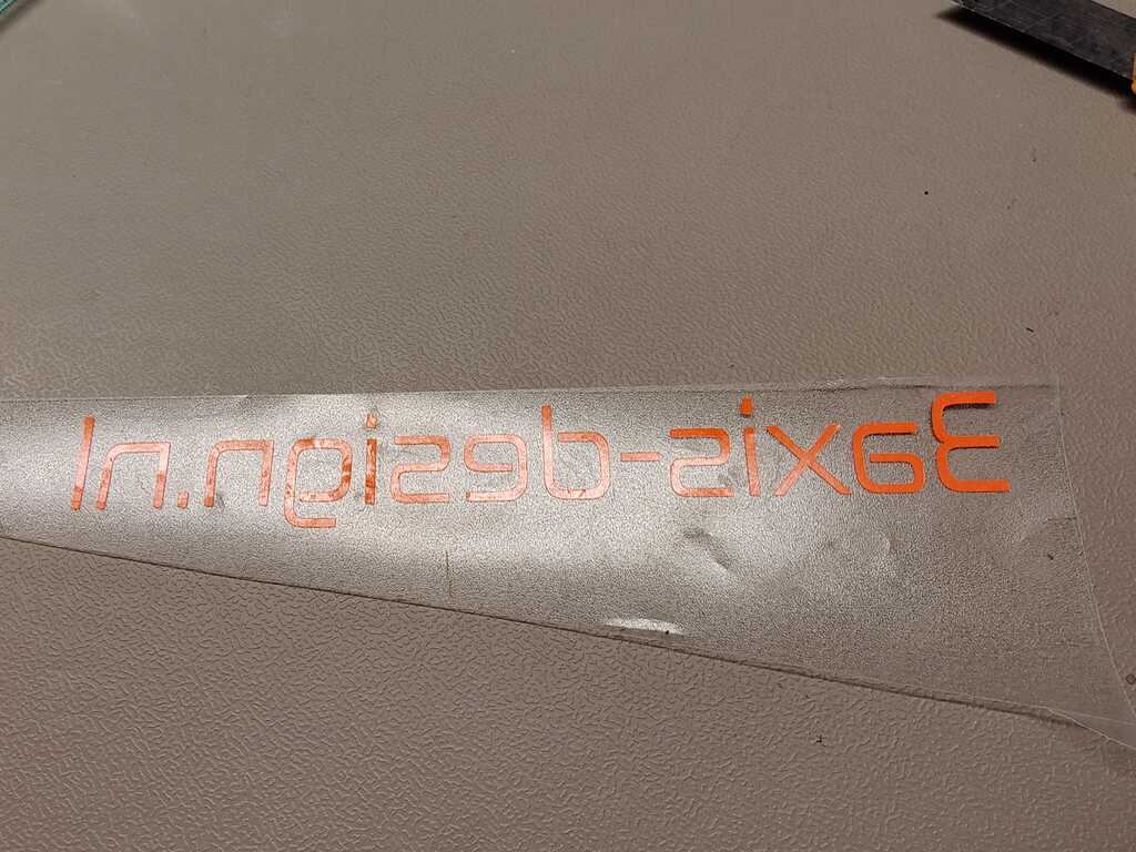
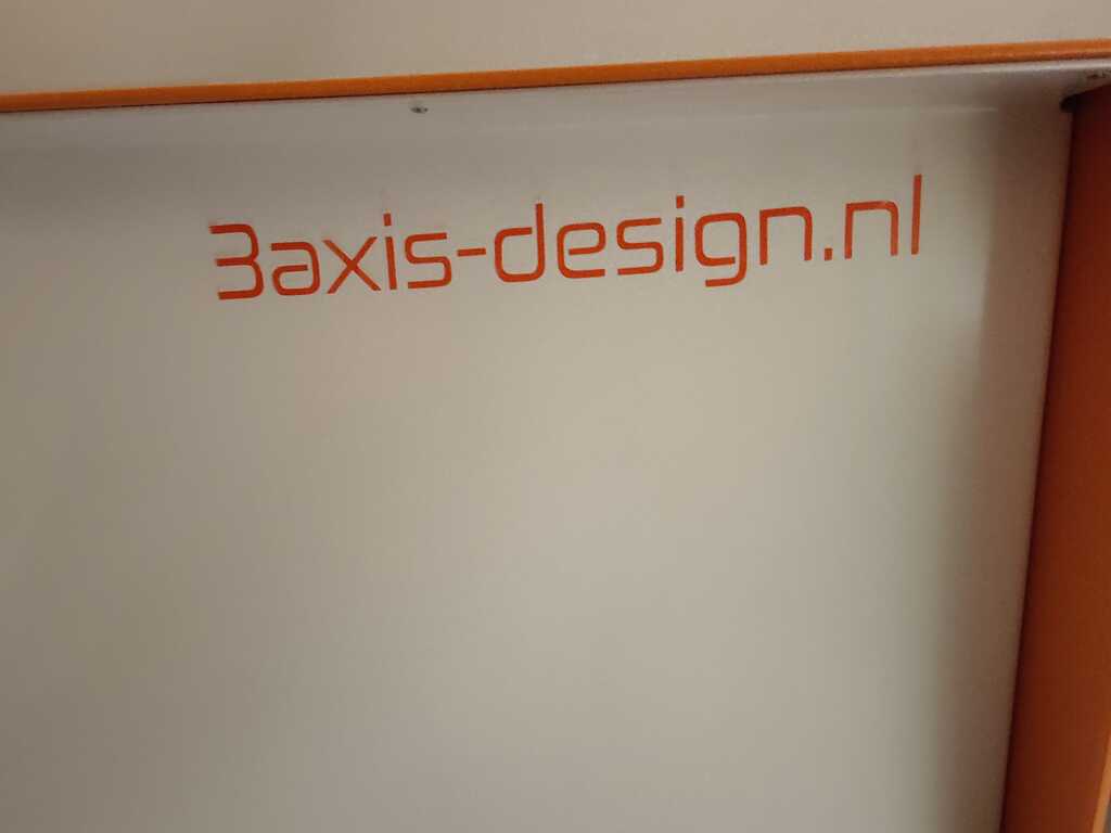
And finally apply the characters to their final destination and carefully remove the foil.
The vinyl file can be found here.
- Having played with a laser cutter before helped greatly in grasping the basic operations and safety instructions.
- The vinyl cutter is underrated, because it has no LAZORZ!!!
- The hexagons did not form a good press-fit. Turns out the second batch of cardboard was 2.6 mm instead of 2.8 mm.
- The vinyl cutter did not cut. Turns out you have to lock the blade into the machine.
- FreeCAD cannot export a sketch as dxf file. You have to turn it into a body first.
- + in LightBurn duplicates a shape, but it often creates doubles of shapes you didn’t intend. So the laser cutter will go over each shape multiple times (because it sees multible shapes.) + and + gives more control over the shapes to duplicate.
- Not much. The week went pretty much as expected. #HappyCamper