12. Outputs
I. Group Assignment
Please refer to Adrian Laveau’s documentation for this week’s group assignment
II. Individual Assignment
Disclaimer
This week’s documentation page mainly documents part of my final project’s board as I wasn’t able to produce any work during the output’s week.
My final project utilises a NEMA14 stepper motor driven by a TMC2208 breakout board produced by FYSTEC. The TMC2208 was selected as it operates the motor with little to no noise emitted.
A. Electronics Design
1. TMC2208 Driver
FYSTEC’s 2208 has a total of 16 IO pins described below.
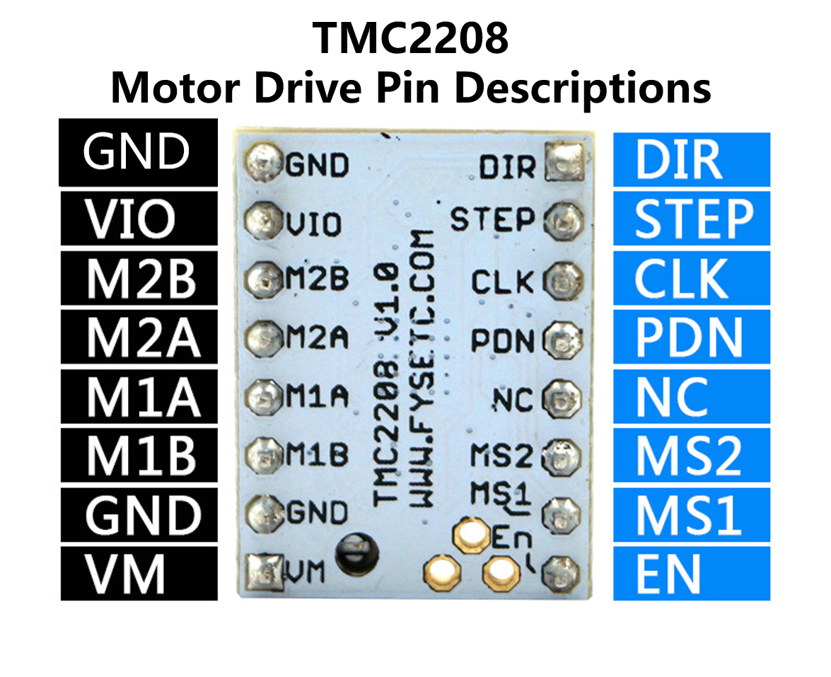
FYSTEC's TMC2208 IO Pins
Pin Descrption
| Pin | Function |
|---|---|
| Power Supply | |
| GND | Ground |
| VM | Motor Supply Voltage |
| VIO | Logic Supply Voltage |
| Motor Outputs | |
| M1A | Motor Coil 1 |
| M1B | Motor Coil 1 |
| M2A | Motor Coil 2 |
| M2B | Motor Coil 2 |
| Control Inputs | |
| STEP | Step-Signal Input |
| DIR | Direction-Signal Input |
| TMC2208 | |
| EN | Enable Motor Outputs: GND=on, VIO=off |
| MS1 | Step-Configuration |
| MS2 | Step-Configuration |
| PDN | UART and Auto Power Down Control: GND=on, VIO=off |
| CLK | Clock Input |
| DIAG | Diagnostics Output |
| INDEX | Index Output |
| VREF | Analog Reference Voltage |
These need to be wired as shown in the below diagram. Furthermore, the Step configuration pins can be connected to VIO to enable micro-stepping through any of four combinations
| MS1 | MS2 | Step | Interpolation | Mode |
|---|---|---|---|---|
| GND | GND | 1/8 | 1/256 | stealthchop2 |
| VIO | GND | 1/4 | 1/256 | stealthchop2 |
| GND | VIO | 1/2 | 1/256 | stealthchop2 |
| VIO | VIO | 1/16 | 1/256 | stealthchop2 |

Wiring Diagaram for TMC2208
2. Board
Taking into consideration the parameters outlined in section A and using the BARDUINO CNC shield as reference, I designed the board in KiCAD. The NEMA14 has a voltage rating of 12V. It is therefore not possible to power it simply using an FTDI connection. The Barcelona lab had a couple of AC/DC power adapters capable of providing a DC Voltage of 12V at 6A. The adapter’s output is given through a barrel jack. As such, a female barrel jack connector was added to the board. Moreover, the copper tracks linking the power source to other components needed to be wider than 0.4 mm in order to allow for a proper heat dissipation and, in extension, prevent the breaking of tracks. The optimal width was calculated to be 2.0 mm on the calculator available at 4PCB.com. Because of this increase in heat, a larger, polarised capacitor of 47uF was used for the driver. Furthermore, I added a 3.3V/1A voltage regulator, allowing me to use the power jack to power the ATTiny1614 microchip. Finally, Jumper Connectors were added to connect the stepping configuration pins to the VIO.
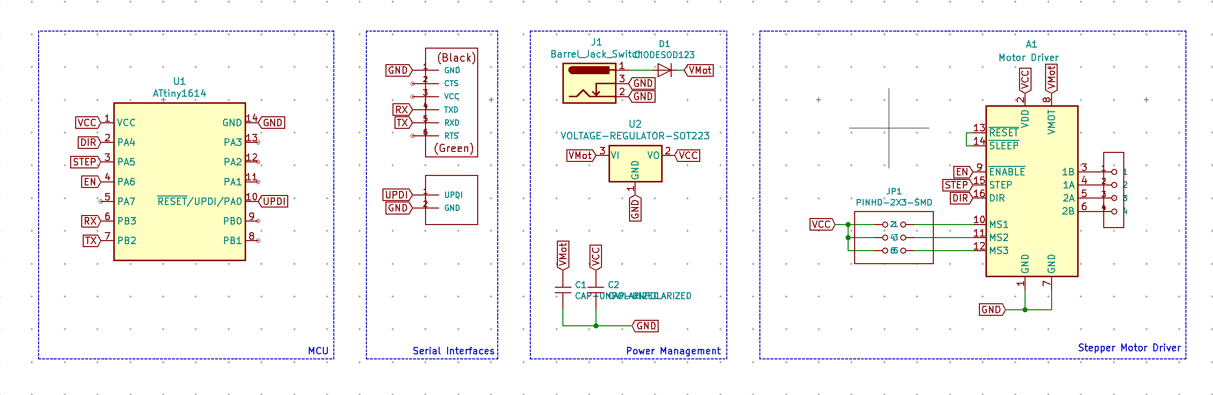
Board Schematics
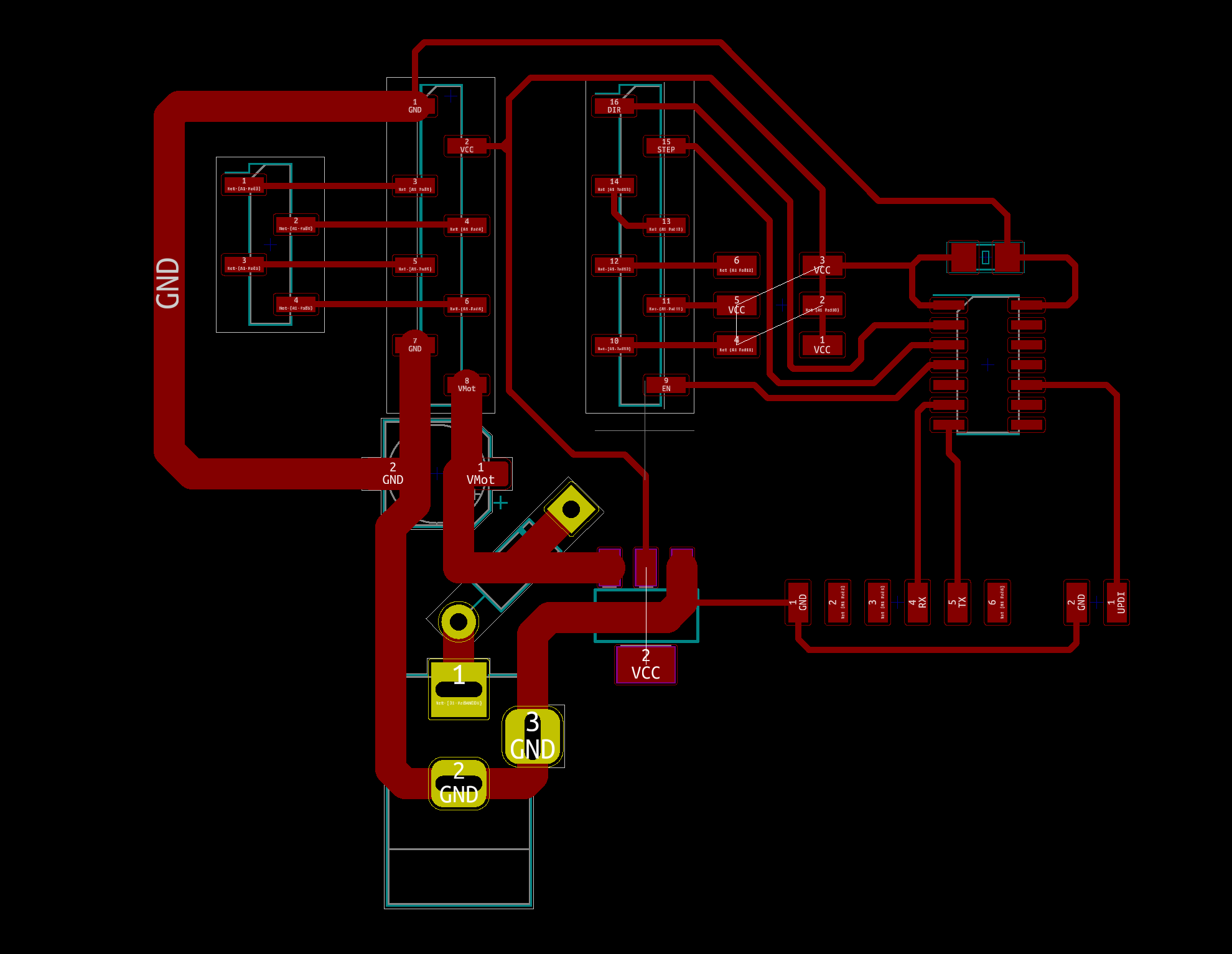
Board Layout
As mentioned in the disclaimer, I didn’t actually produce this board. I will be using my final project’s boards for the rest of the assignment. The only differences between the two with regards to the stepper motor driver is that an ESP32 is used instead of an ATTiny1614, and that the power jack connector is situated on a another board connected to the central one with jumper cables. As explained in the project’s documentation. This central board’s design was faulty as certain GND tracks weren’t set to the correct width, causing them to break when connected to the source. I therefore had to use wires all around. The updated design is also shown below but I had no time to produce it.
Final Project Boards - Copied from final project documentation
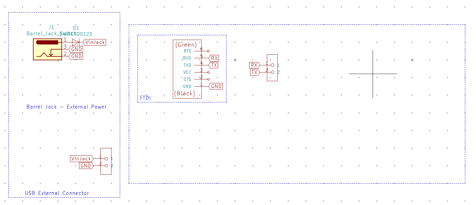
Interface Board Schematic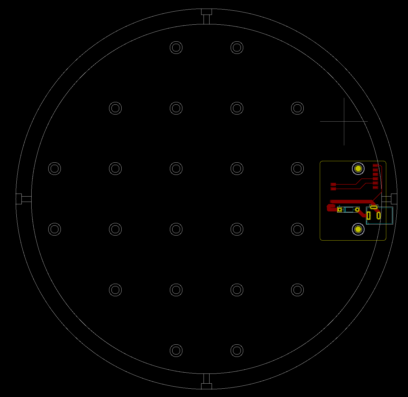
Interface Board Layout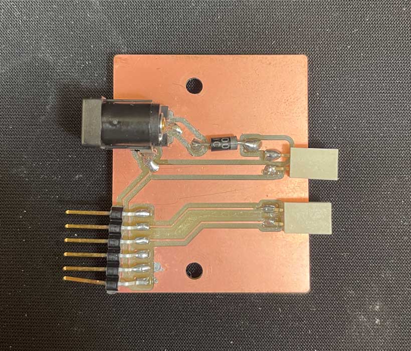
Soldered Interface Board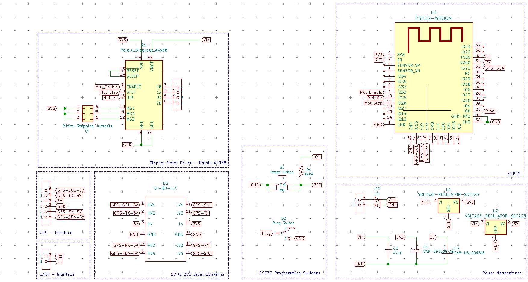
Central Board Schematics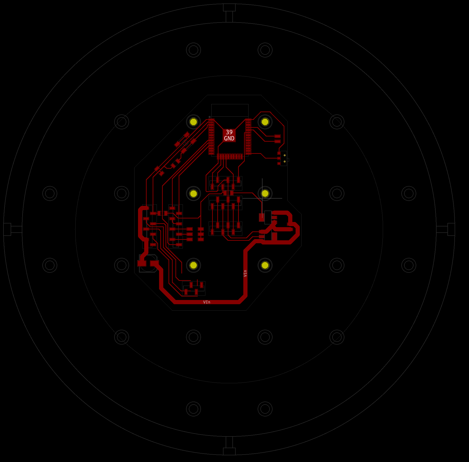
Faulty Layout of Central Board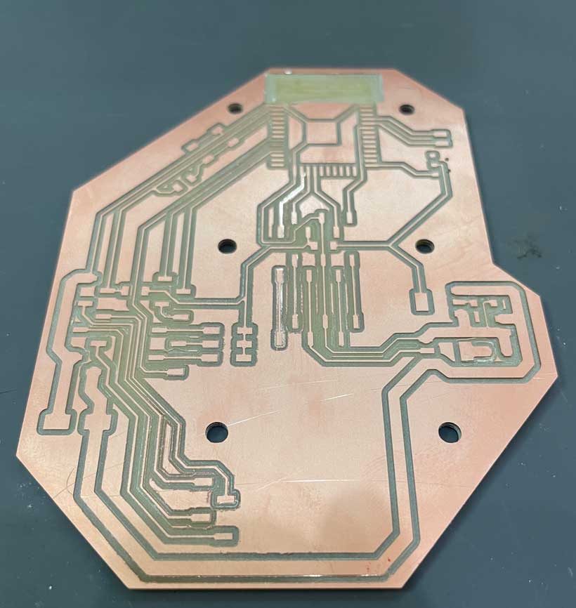
Milled Faulty Central Board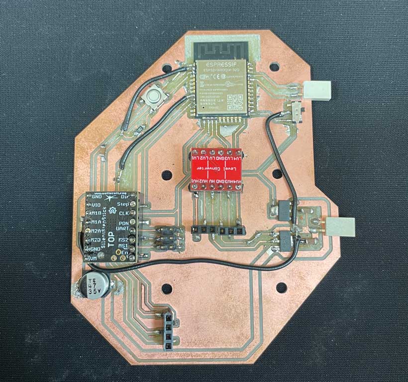
Assembled Faulty Central Board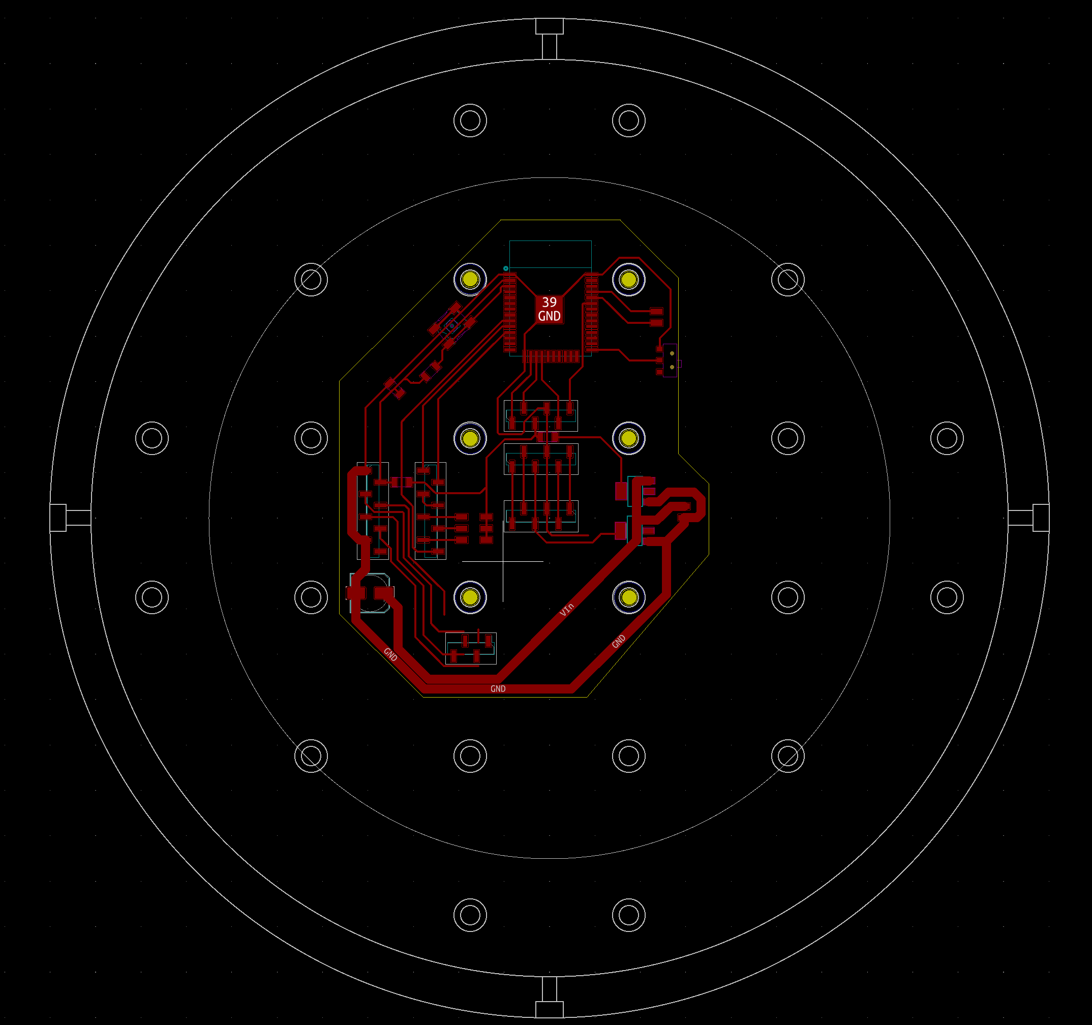
Corrected Layout of Central BoardB. Operation
1. Stepper Driver Setup
The driver features an adjustable potentiometer which sets the current fed to the motor. This potentiometer needs to be set manually to a voltage value (Vref) relative to the current rating of the motor being used. Vref is calculated with the following equation: Vref = (Irms * 2.5V) / 1.77A = Irms * 1.41, where Irms = Current per Phase.
The potentiometer is a flat-headed screw. Vref is increased by turning the screw clockwise, and decreased by turning it counter-clockwise. A multimeter can be used to measure the value of Vref by placing one probe on a grounded pin and the other on a Vref pin, as shown in the below diagram.

TMC2208 Vref Setup DiagramThe 35x35x35mm NEMA14’s datasheet specifies that its rated current is of 1.0A, giving a Vref of 1.44V. I went for a current of 0.5A, a Vref of 0.72A.
2. Programming
Basic Stepper Control
Building upon what what I worked on for Week 9, I first tested the circuit with the two following codes. The “basic” code simply rotates the shaft in a given direction. The “Direction Change” program rotates the shaft back and forth.
Video Demo
1 2 3 4 5 6 7 8 9 10 11 12 13 14 15 16 17 18 19 20 21 22 23 24 25 26 27 | |
Video Demo
1 2 3 4 5 6 7 8 9 10 11 12 13 14 15 16 17 18 19 20 21 22 23 24 25 26 27 28 29 30 31 32 33 34 35 | |
Going Further - AccelStepper Library
My current understanding of stepper motors limits what I can achieve with them. Features I am looking to implement are: acceleration and deceleration at the start and end of an operation and rotation by a specific angle. Luckily, the accelstepper library offers a set of pre-defined functions which can be used for these purposes.
First and foremost, when using the AccelStepper library, the stepper motor must be initialised using the following command outside of any function:
AccelStepper stepperName(AccelStepper::DRIVER, stepPin, directionPin);
Then, the motor must be enabled in setup() function using:
digitalWrite(Motor_Enable, LOW);
Finally, the maximum speed, and optionally the acceleration, of the motor need to be defined in the setup function as well through:
stepper.setMaxSpeed(maxSpeed); In Steps per second
stepper.setAcceleration(Acceleration); in Steps per Secondˆ2
Relative position rotation means that the rotor is moved by a specific number of steps relative to its current position. with the accelStepper library, this can be achieved by the combination of the following three commands.
1 2 3 | |
the .move(steps) attribute indicates the motor must be turned by a number of steps, regardless of its current position. this must be followed by a .setSpeed(speed) attribute. Then, any of the .run() attributes can be called to launch the rotation of the motor’s shaft. Non-blocking attributes must be called in an event loop. On the other hand, blocking attributes pause the program until the motor reaches the specified position.
An absolute position rotation means the rotor is moved to a specific step based position relative to its initial “Zero” position. this can be achieved by the combination of the following three commands.
1 2 3 | |
The main difference between with a relative position chain of commands is that .move(steps) is replaced by .moveTo(step).
| Attribute | Description | Blocks |
|---|---|---|
| .run() | Poll the motor and step it if a step is due, implementing accelerations and decelerations to achieve the target position. Each call to run() will make at most one step. Must call this as frequently as possible, but at least once per minimum step time interval, preferably in the main loop. | No |
| runSpeed() | Poll the motor and step it if a step is due, implementing a constant speed as set by the most recent call to setSpeed(). Must call this as frequently as possible, but at least once per step interval. | No |
| .runToPosition() | Moves the motor (with acceleration/deceleration) to the target position and blocks until it is at position. Dont use this in event loops, since it blocks. | Yes |
| .runSpeedToPosition() | Runs at the currently selected speed until the target position is reached. Does not implement accelerations. | Yes |
| .runToNewPosition() | Moves the motor (with acceleration/deceleration) to the new target position and blocks until it is at position. Dont use this in event loops, since it blocks. | Yes |
.setSpeed sign
if a negative number of steps is given in the .move()/.moveTo() attribute, the defined speed must be set as negative or else the motor will rotate in a positive direction for a few seconds and then in the negative direciton.
I composed a program that allows me to switch between three modes. An absolute positioning, relative positioning and interruptable positioning system. A user can define a specific angle by which the motor should move by entering a value in the serial monitor. Furthermore, switching between modes is achieved by typing “abs” (absolute), “rel” (relative) or “opt” (interupt).
The interuptable relative positioning system was designed to allow for the direction of rotation and number of steps by which the motor rotates to be changed while it is already running. This is achieved with the following if loop:
1 2 3 4 5 6 7 8 | |
If a user enters a value while the motor is running, the rotation is halted with .stop(). Then, if the interruptable relative operation is selected, the zero position of the motor is changed to that at which it has stopped. If the value entered by the user is different than zero, the motor starts rotating to that new position.
I believe that this will be of tremendous help for my final project as it would allow for the motor to swiftly change direction if the trackde object does so. The program can be found below.
Interrupt - Video Demo
1 2 3 4 5 6 7 8 9 10 11 12 13 14 15 16 17 18 19 20 21 22 23 24 25 26 27 28 29 30 31 32 33 34 35 36 37 38 39 40 41 42 43 44 45 46 47 48 49 50 51 52 53 54 55 56 57 58 59 60 61 62 63 64 65 66 67 68 69 70 71 72 73 74 75 76 77 78 79 80 81 82 83 84 85 86 87 88 89 90 91 92 93 94 95 96 97 98 99 100 101 102 103 104 105 106 107 108 109 110 111 112 113 114 115 116 117 118 119 120 121 122 123 124 125 126 127 128 129 130 131 132 133 134 135 | |