7. Computer Controlled Machining
I. Group Assignment
- test runout, alignment, speeds, feeds, materials, and toolpaths for your machine
We started from a file prepared by students from last year’s Barcelona class. We then added a couple of tests a few of us came up with to extract as many characteristics of the 15mm thick plywood plates we had at the lab.
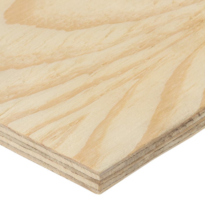
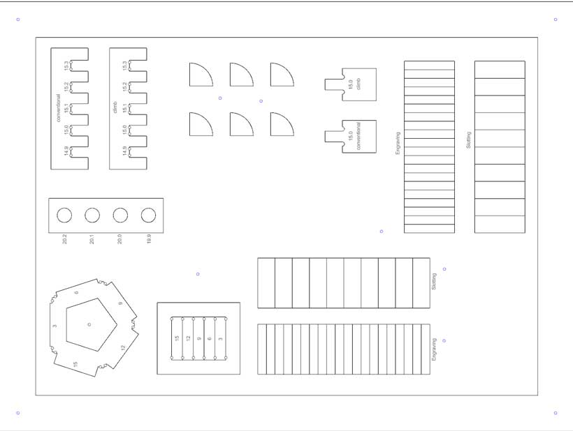
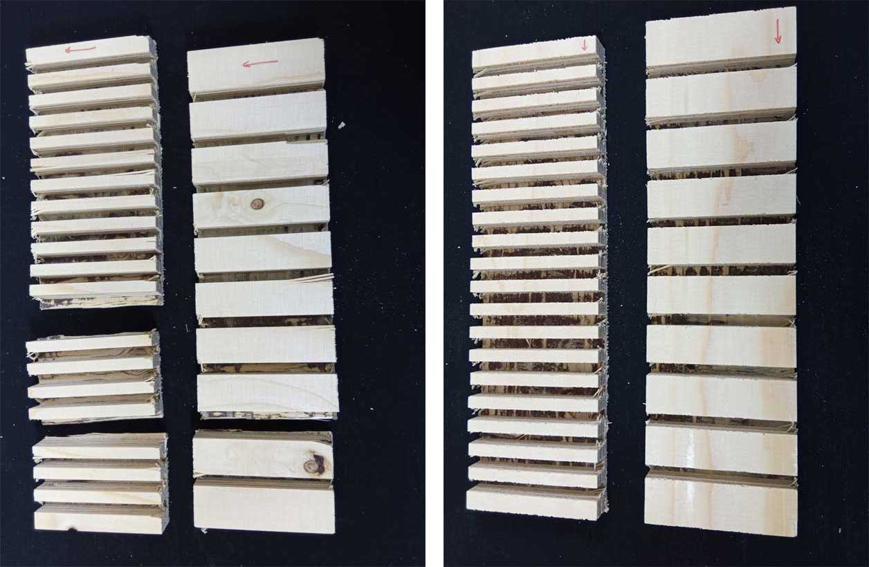
This test aimed to determine how flexible the plates were. The plates are composed of five layers, each 3mm thick. The top, middle and bottom layers’ grain is oriented in the same direction, which is perpendicular to that of the second and fourth plates. As such, we designed striated pieces, with 12mm deep streaks. such a depth would leave a single surface layer and allow us to test the flexibility of the wood with and against the direction of its grain.
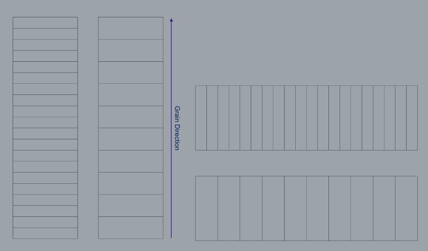
Wood is an anisotropic material. We therefore expected less flexibility but sturdier properties for cuts along the grain. This was indeed the case. The cuts against the grain required less force to bend but failed after a 3 tries. The rest required more force but remained in one piece.
Please refer to Carla’s excellent documentation for the work carried out for the group assignment.
II. Individual Assignment - Parametric table
This assignment offers a great occasion for me to enhance my parametric design skills. I set out to design an object based on an abstract 3D shape, and composed of sheets of wood. I was heavily inspired by Ora Ito’s staircase designed for LVMH’s headquarters. Further research into similar parametric design methods revealed a wide array of objects conceived following the same principles. I’ve compiled a list of those I found most interesting below.
Inspiration


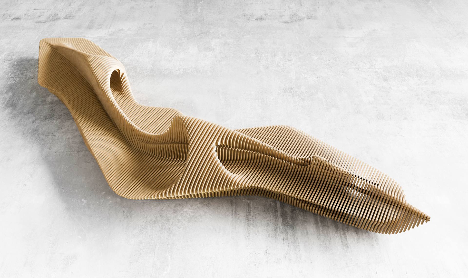
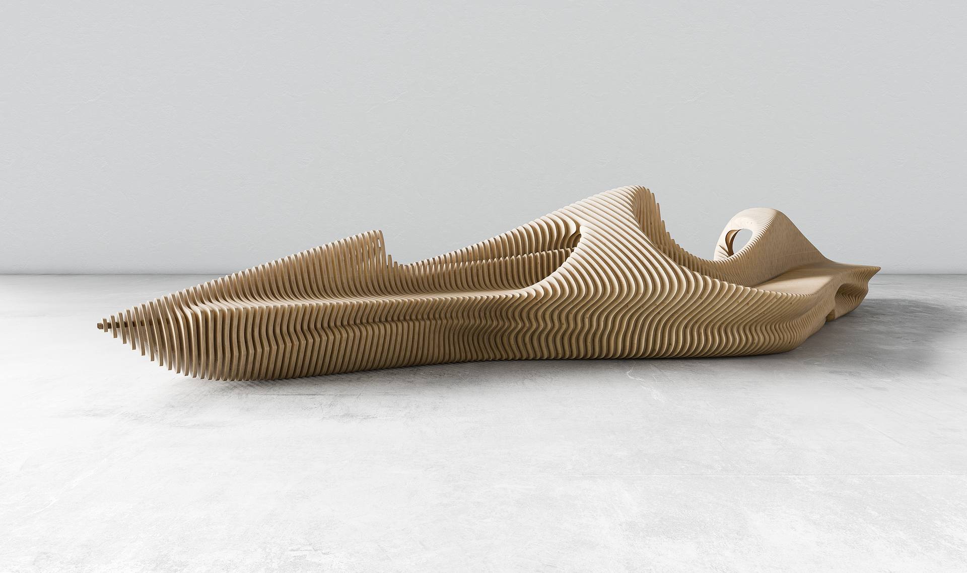

I decided to design a table with a structure similar to the projects depicted above.
a. CAD
I didn’t really know where to start. I found the below tutorial in which grasshopper is used to design a “parametric bench”, similar to what I hoped to achieve.
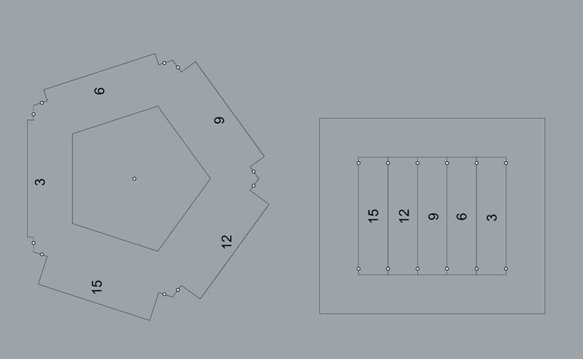
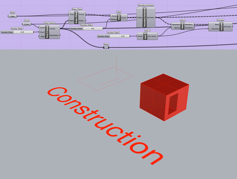
The tutorial basically teaches how to extract the profile of a set number of sections of a 3D volume located at a fixed distance from each other. These can then be manipulated as desired. I used what I learned from it to section a rectangular volume with a hole on one of its sides into a parametric table, as shown below.

This part of the program slices the starting geometry. It takes both the geometry and a line as inputs. The line is used to define the slicing planes. I used both a horizontal and a vertical line.
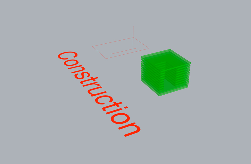
The following is obtained if the horizontal line is selected as an input.
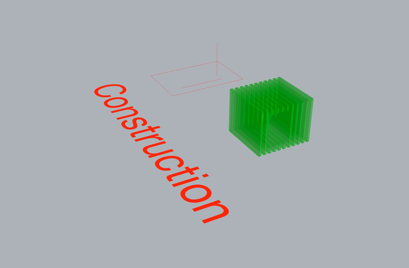
The following is obtained if the vertical line is selected as an input.
Joints
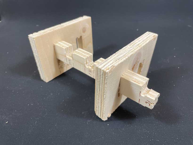
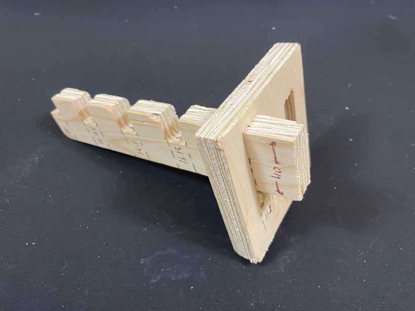
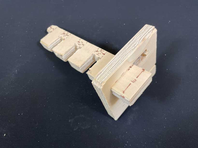
With that being done, I needed to find a way to allow for this parametric table to hold together. I thought of a rail system in which rectangular beams with slots at set distance intervals in which the plates would be sandwiched. I am unsure if joint is the correct term for such a system but I’ll be using it to keep things simple.
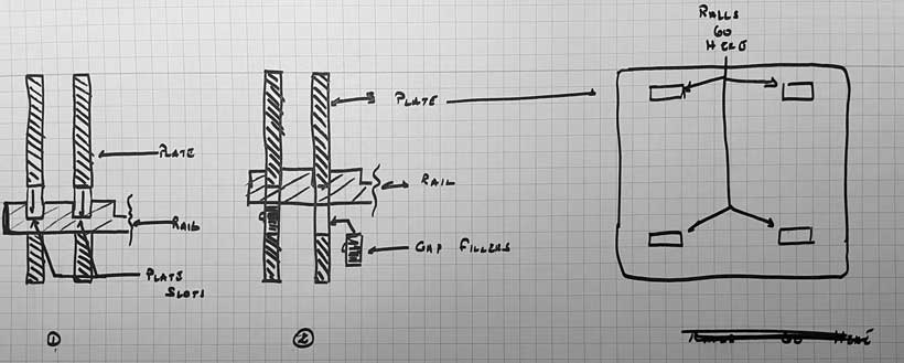
As depicted above, four rails would be inserted through holes placed near the corners of the plates. Each plate would then be inserted in a slot, holding it in place similarly to a press-fit. This would leave a gap at the back of the rail which would be filled with small pieces of wood acting as ‘gap fillers’.
I was unsure of the efficiency of the joint system and therefore opted to test it out at first. I looked to determine the optimal dimensions for the different elements of the rails and gap fillers. I derived a test that would allow me to verify the following four parameters:
-
Width and depth of plate slots needed to firmly hold the rail on a plate.
-
Rail Width needed for the structure to b stable once assembled
-
Plate hole Dimensions required to ensure the rails could be easily
-
Thickness of gap fillers that would enable them to be maintain the plate in position while remaining easy to insert and remove.
to that I end, I designed joint components with various dimensions as shown below.
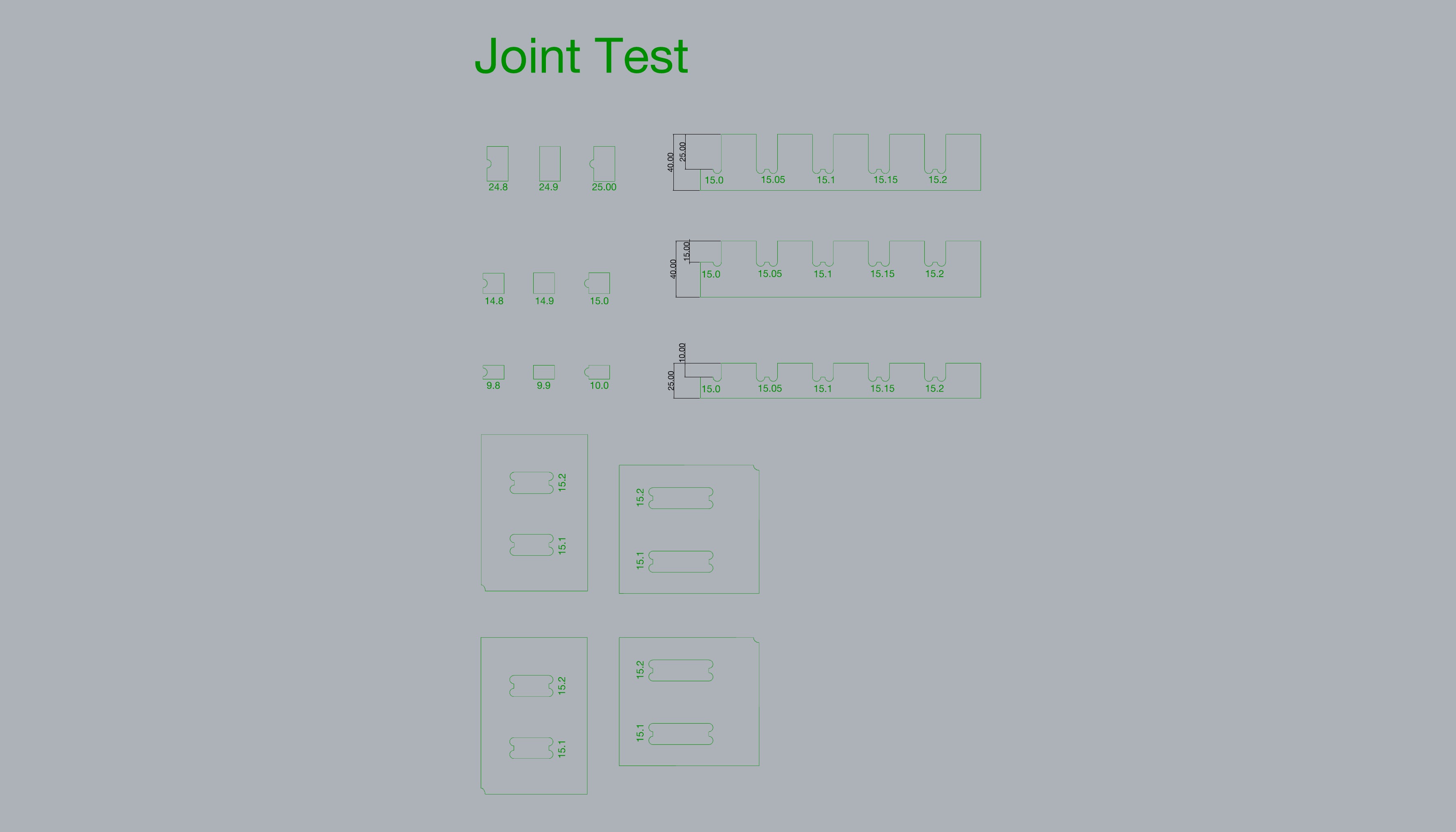
Nested Joint Test Componentsc. Milling
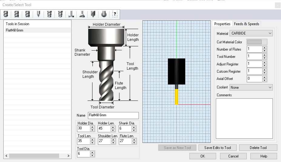
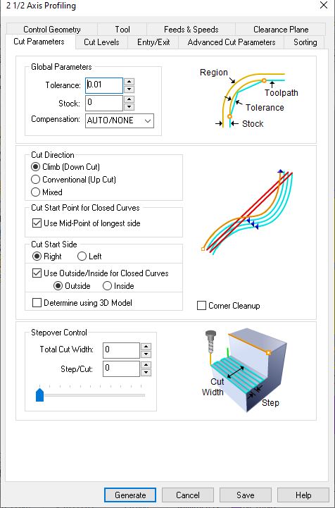
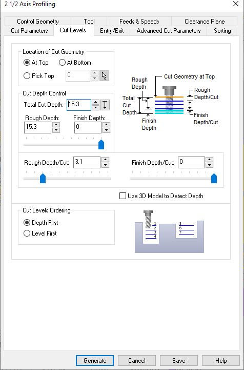
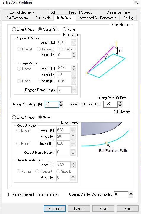
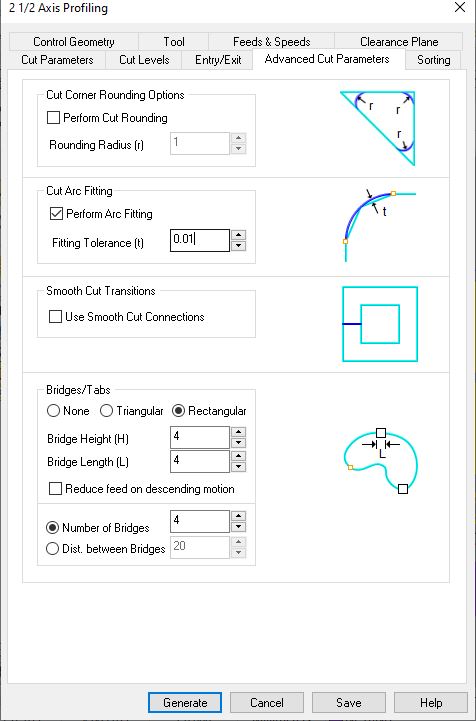
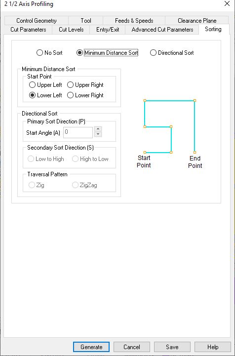
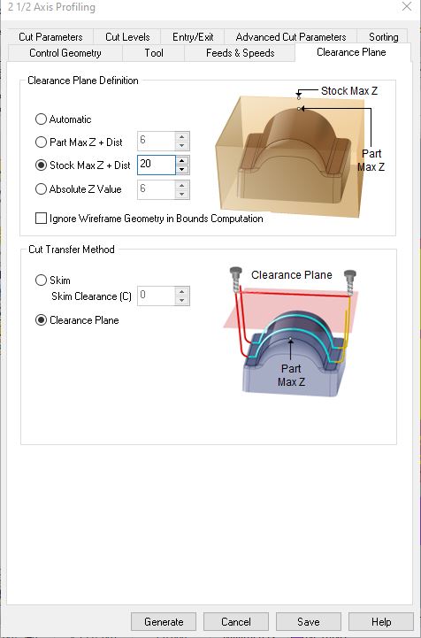
Files used for milling were all produced in RhinoCAM and operations were executed with a 6mm flat end-mill. I first set the tool’s characteristics. Components were milled using either profilling or engraving operations, whose parameters were derived from the tests made for the group assignment, and are shown below.

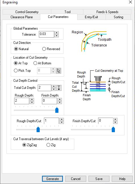

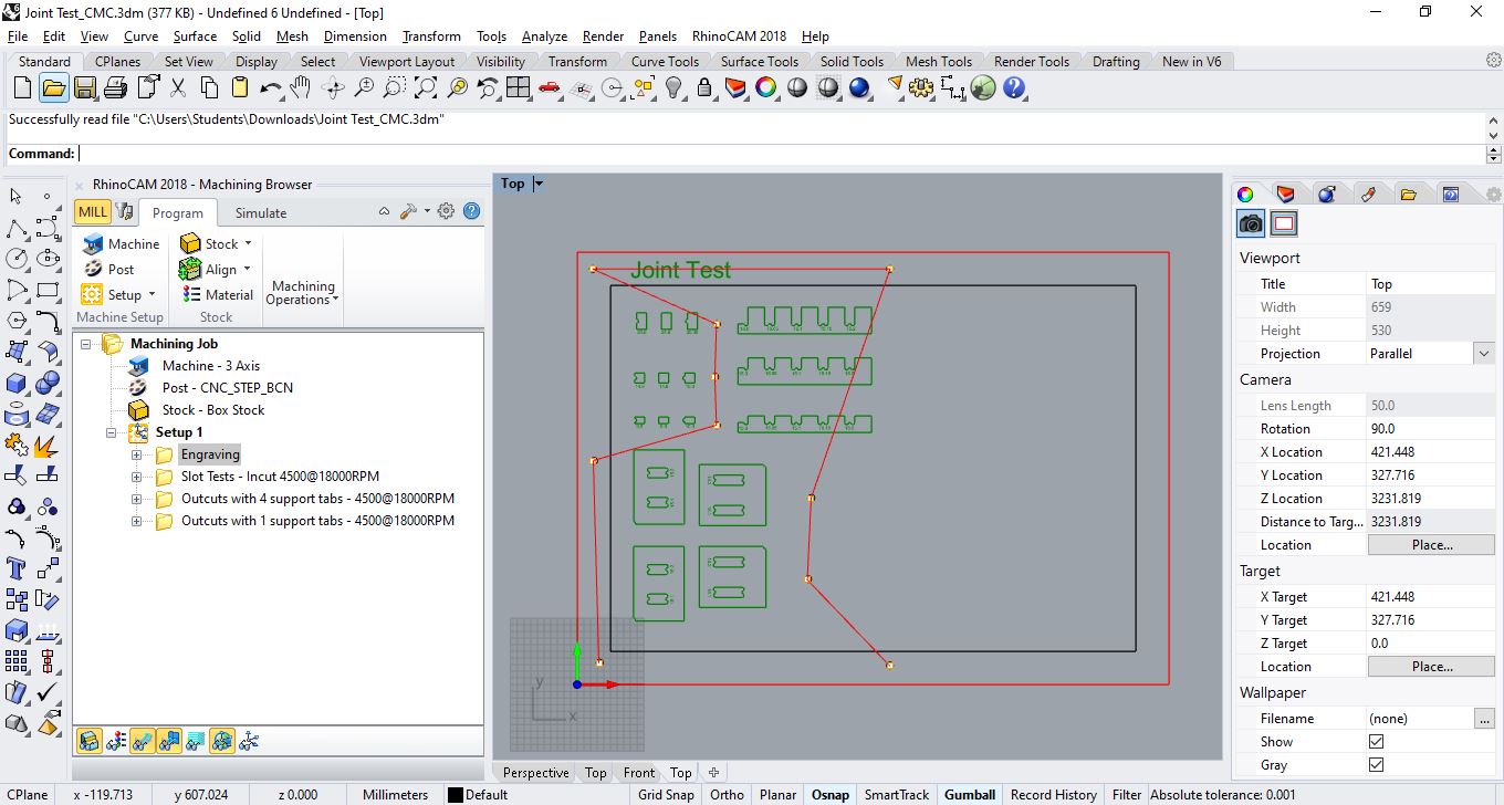
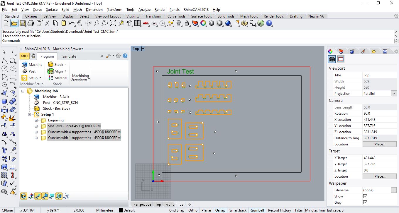
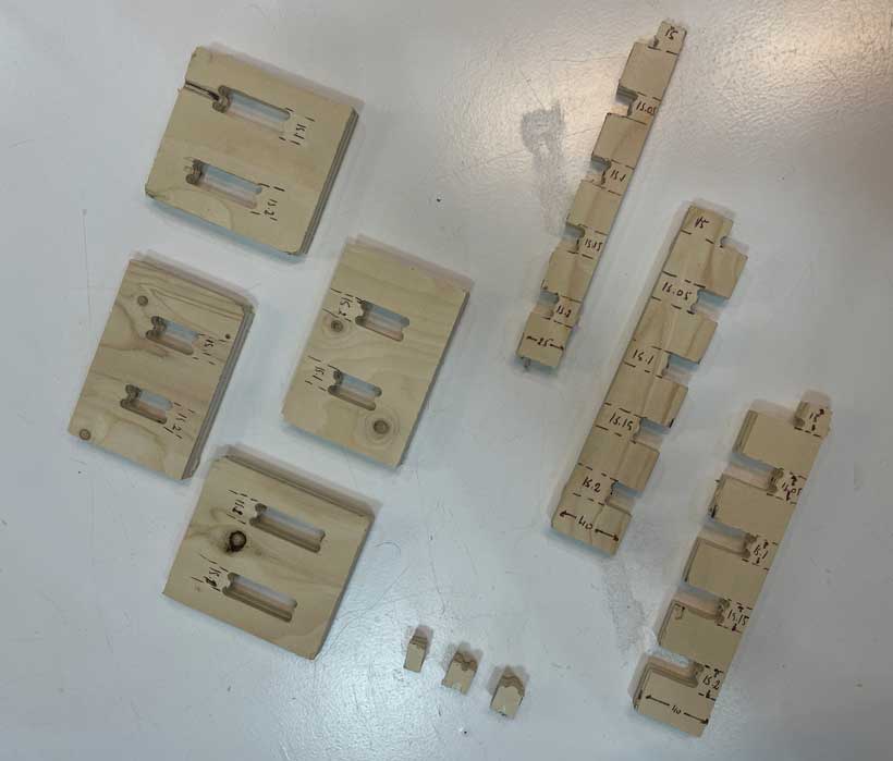
1. Joint Test
All pieces were milled with a profiling operation. However, in order to ensure the plate of wood used as well as milled components wouldn’t move, everything had to be fastened in place with screws. The position of these screws needed to be set manually in RhinoCAM to avoid placing them on the toolpath. Engraving operations of a short depth of 1mm were used to mark these locations.
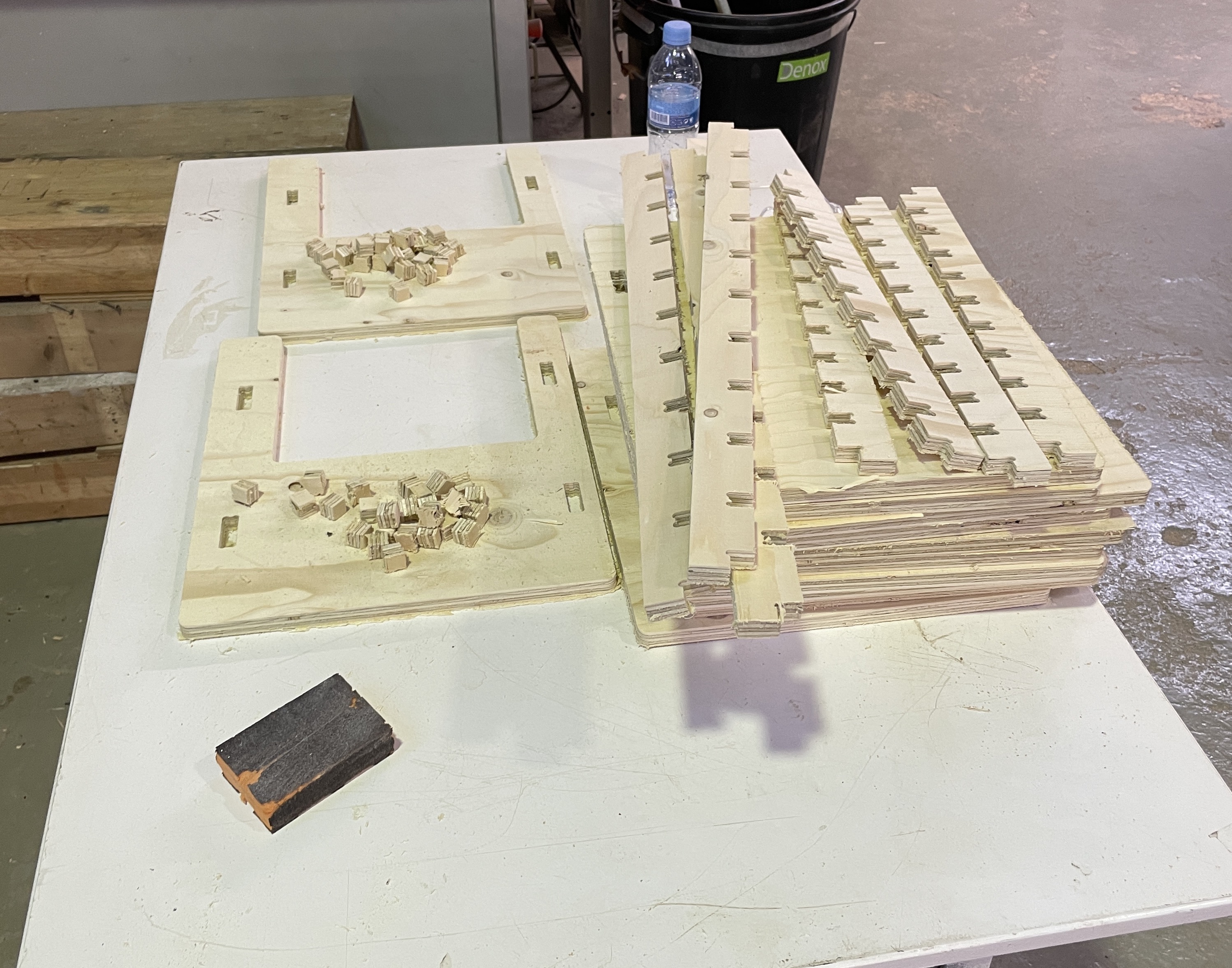
Once the components had been milled, I proceeded to the test. I found that the combination of 40 mm wide rails with 15.2 slots, 15.0 gap-fillers and 15.2 through holes offered great stability while remaining easy to assemble. The 15 mm or 40/25 mm rails were not stable enough to hold the whole table.
2. Table Components
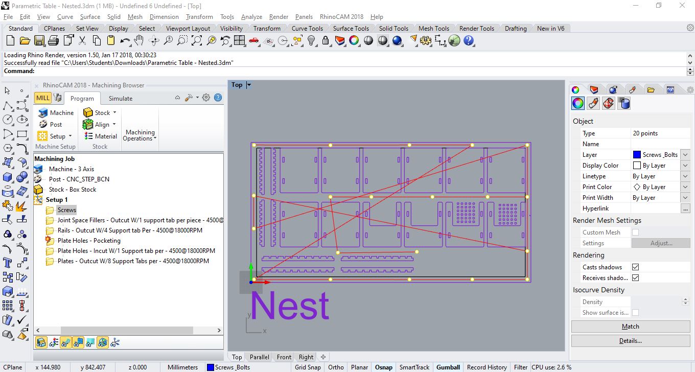
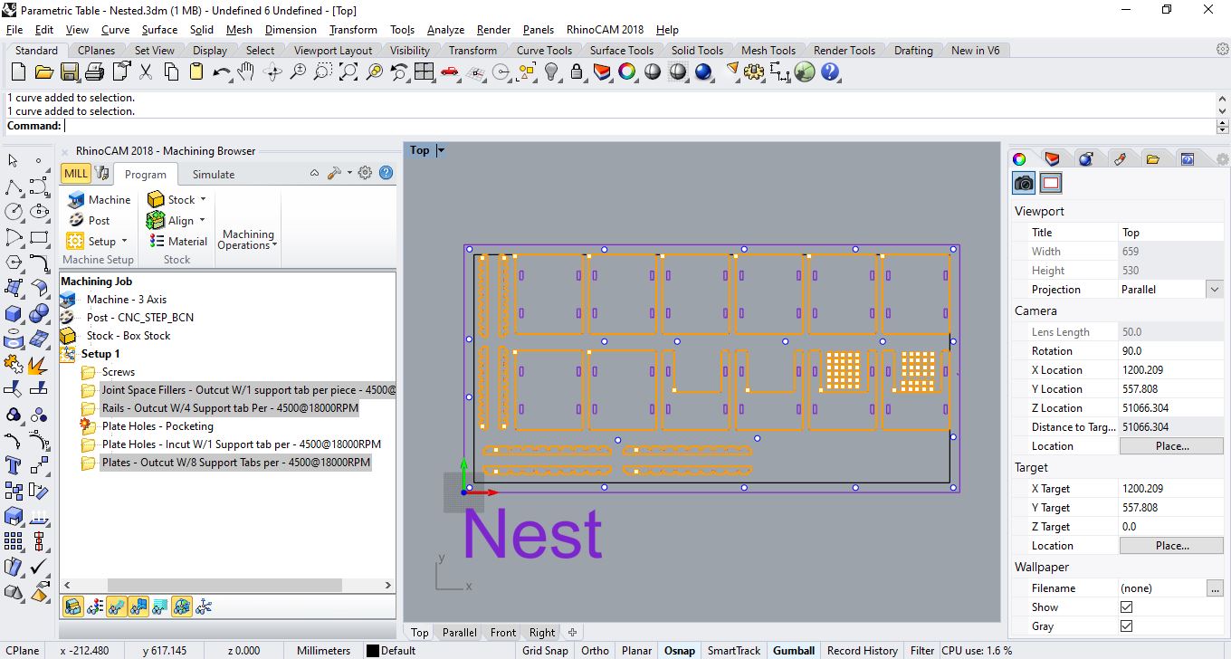
Following the joint test, I moved to milling the components for the table. The grasshopper program I was using extracted the profiles of each slice of the starting geometry. I selected the horizontal slicing option, composed of a total of 12 plates. Moreover, I milled two sets of four rails. One in which the plate slots were placed at 10 mm from one another. Another where they were placed at 20mm from one another. The nested components are shown below.
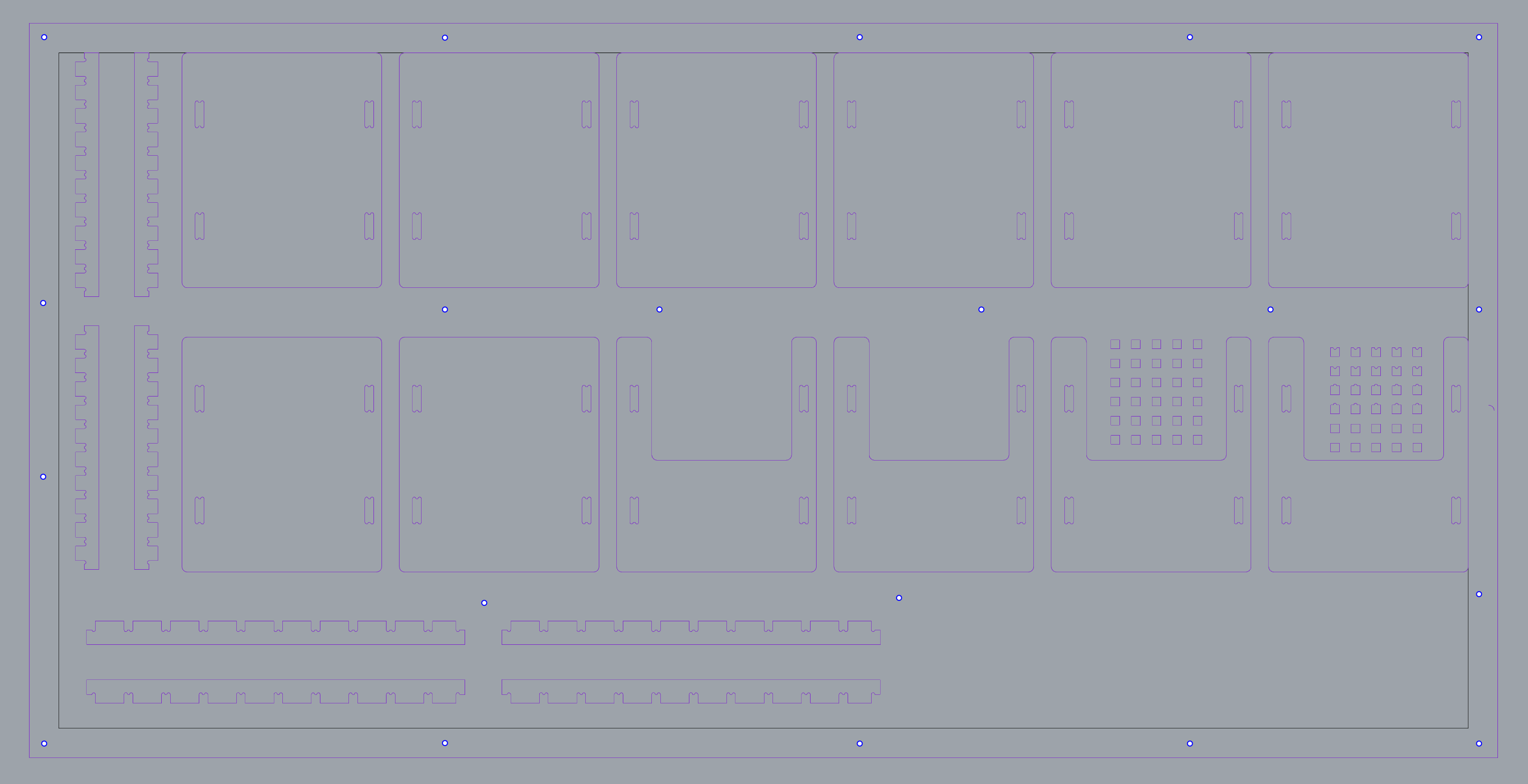
Nested Table ComponentsHere again profiling operations were used to cutout all of the components. However, I had used a pocketing operation to cutout the through holes for the rails. Similarly to the joint test, an engraving operation was used to mark the location of fasteners.
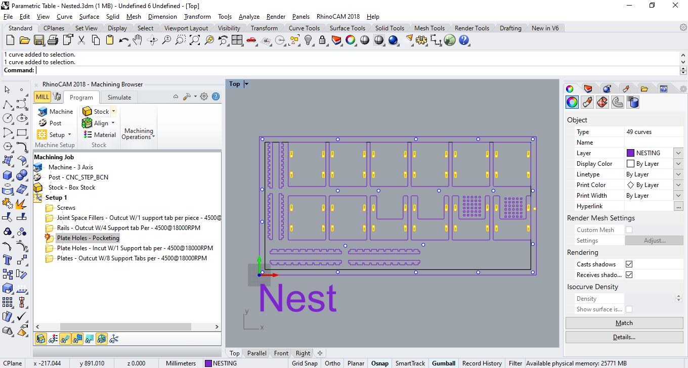
Unfortunately, I forgot to set the stock parameter in the slotting operations used for the through holes. As such, the holes were narrower than planned by a total of 1.27 mm in both width and length.
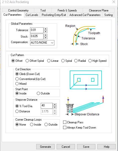
Incorrect Stock value for Slotting operation
I therefore had to mill the rails again, shaving off at least 1.3mm in their thickness using an engraving operation.
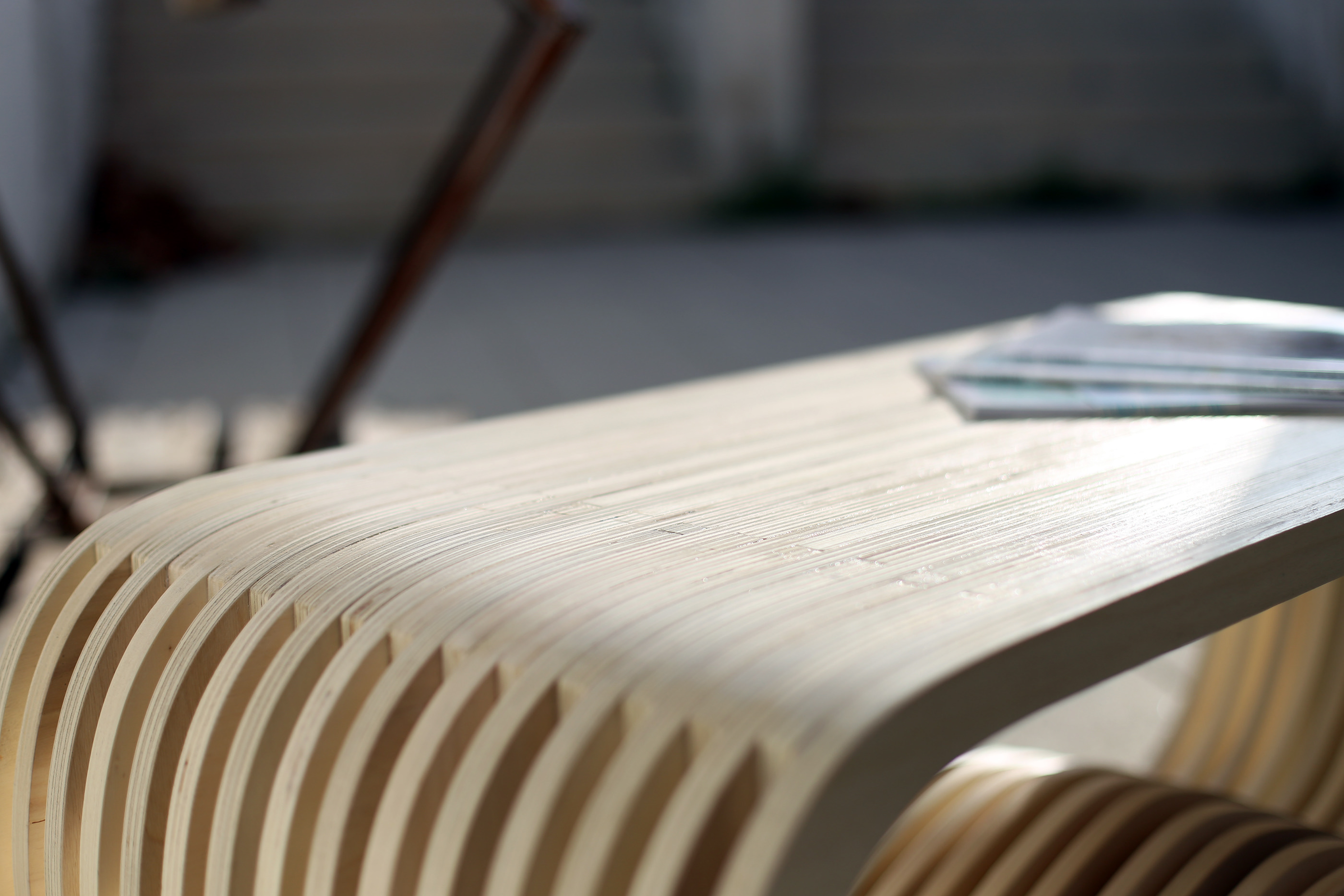
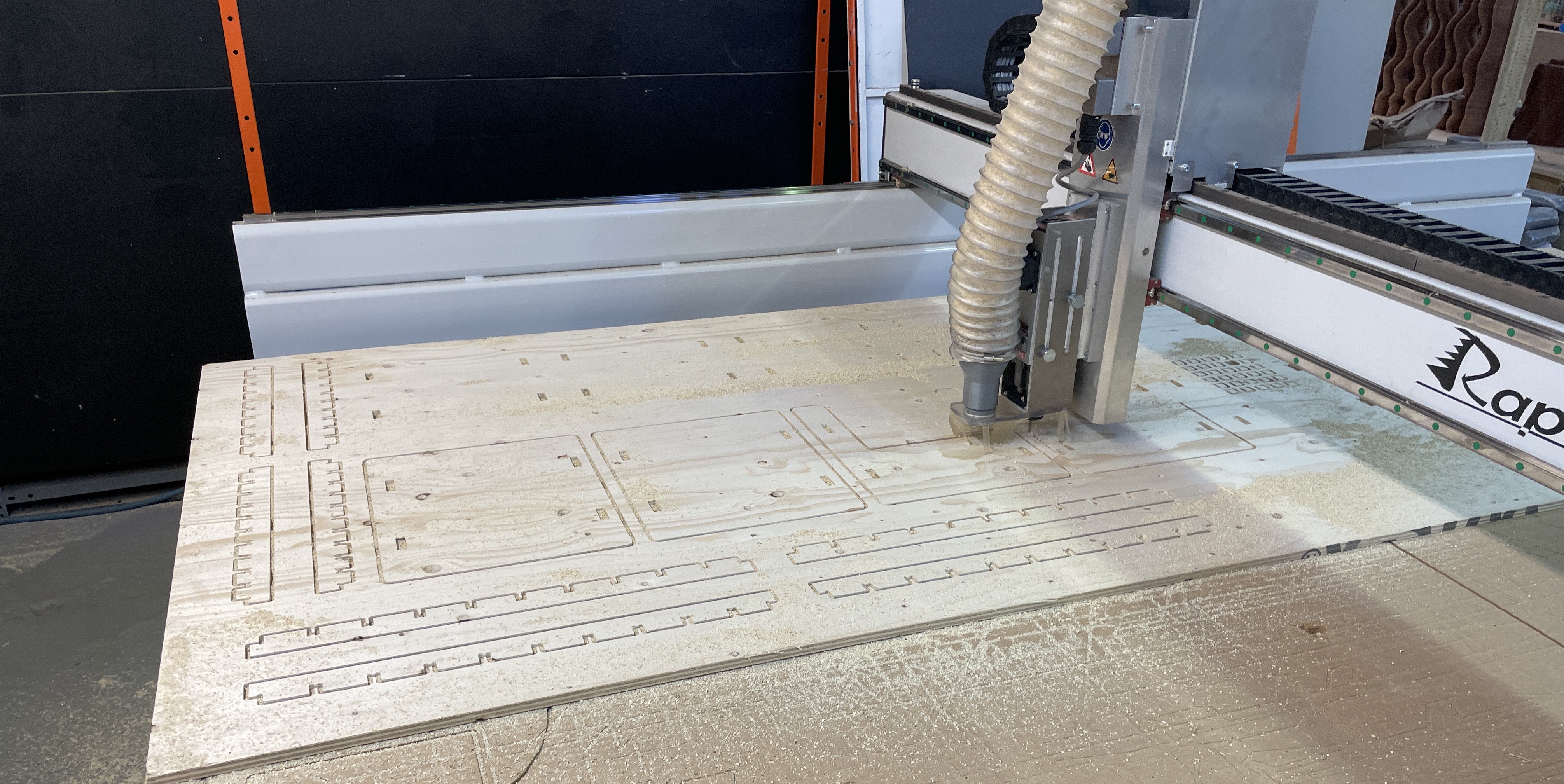
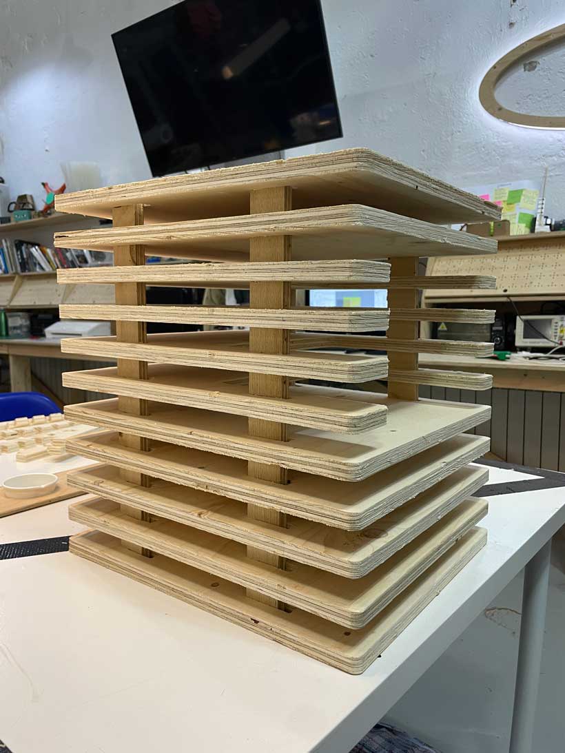
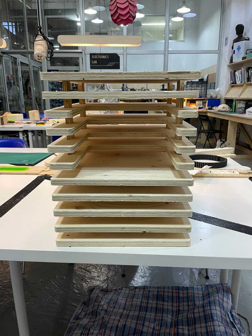
c. Final Result
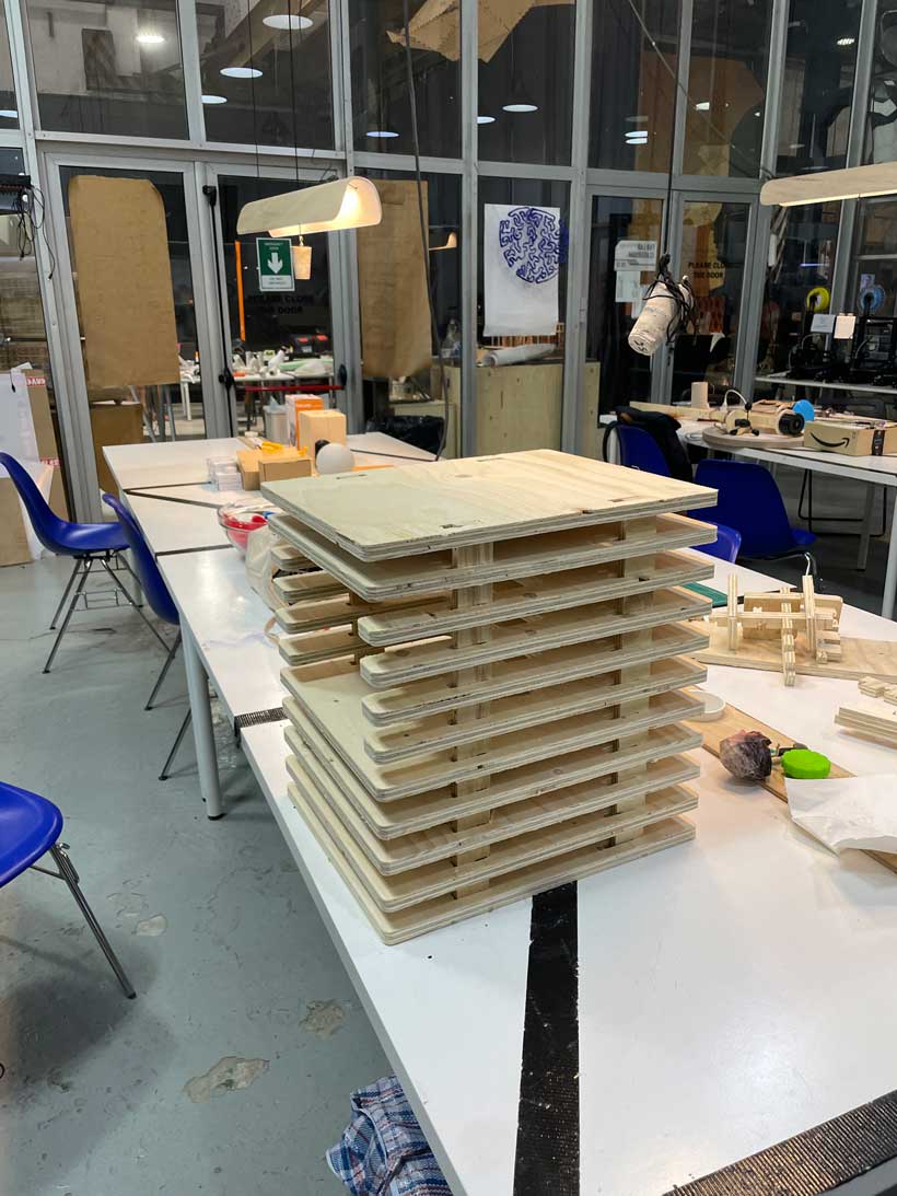
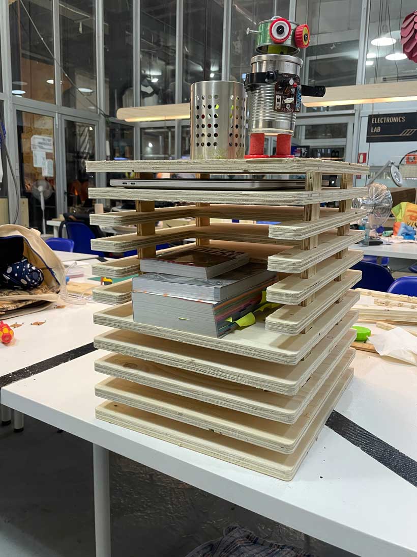
III. Files
Week 07 Files
Group Assignment Files - includes 3D model file and all G-Code scripts used
Individual - Joint Test Vectors
Individual - Parametric Table Grasshopper Program
Individual - Parametric Table Vectors
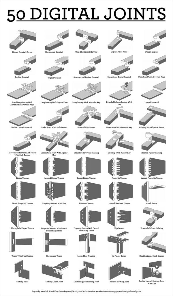
Reference - 50 Digital Joints
CNC Milling - Basic Concepts
a. Key Terms
Tools
Tools Table
| Tool | Function/Description | Picture |
|---|---|---|
| End-Mill |  |
|
| Up End-Mill | 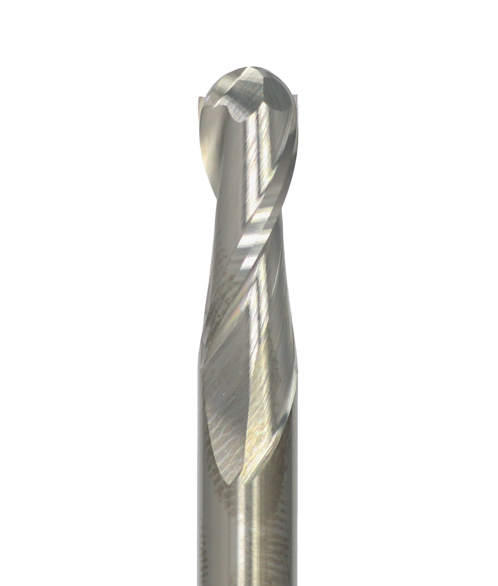 |
|
| Down End-Mill | ||
| Straight End-Mill | ||
| Compression End-Mill | ||
| Flute | ||
| Collet |  |
|
| Sacrificial Board | ||
| Spindle |
Parameters
Spindle Speed - Speed at which the end-mill will rotate (expressed in RPM)
Feed Rate - Speed at which tool moves in space (expressed in mm/s)
Operation
Slotting - Create a slot by milling over a curve to a certain depth.
Engraving - Engrave by sweeping an area until a specified depth is reached.
Pocketing - Mill a pocket by sweeping an area until a specified depth is reached.
Profiling - Mill the boundaries of a closed geometry.
b. G-Code - Fundemental Commands
| Command | Function | Description |
|---|---|---|
| G00 | Rapid Positioning | Moves the machine at maximum travel speed to specific coordinates |
| G01 | Linear Interpolation | Instructs the machine to move in a straight line at a set feed rate or speed towards specific coordinates |
| G02/G03 | Circular Interpolation Clockwise / Counterclockwise | Instructs the machine to move clockwise / counterclockwise in a circular pattern |
| G20/G21 | Units Selection | inches/millimeters |
| G17/ G18/ G18 | G-code Plane Selection | XY / XZ / YZ plane |
| G28 | Return Home | Instructs the machine to move the tool back to a predetermine position |
| G90/G91 | Positioning G-code commands | Absolute / Relative Positioning |
| M00 | Program stop | |
| M02 | End of program | |
| M03 | Spindle ON – clockwise | |
| M04 | Spindle ON – counterclockwise | |
| M05 | Spindle stop | |
| M06 | Tool change | |
| M08 | Flood colant ON | |
| M09 | Flood colant OFF | |
| M30 | End of program |