15. Wildcard - Printing a Clay Structure
For this week’s assignment, I decided to try printing a clay structure using one of the 6-axis robotic arm available here at the Barcelona FabLab

Inspiration
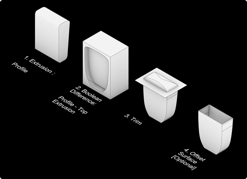
I was unsure of the geometrical constraints imposed by the material. Namely slope angles and layer thickness. As such, I kept the geometry simple. I used The Egg, a ruined cinema building located in Beirut, as a general source of inspiration.


Creating the model
Procedure
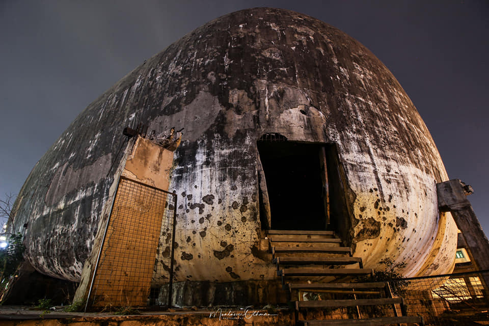
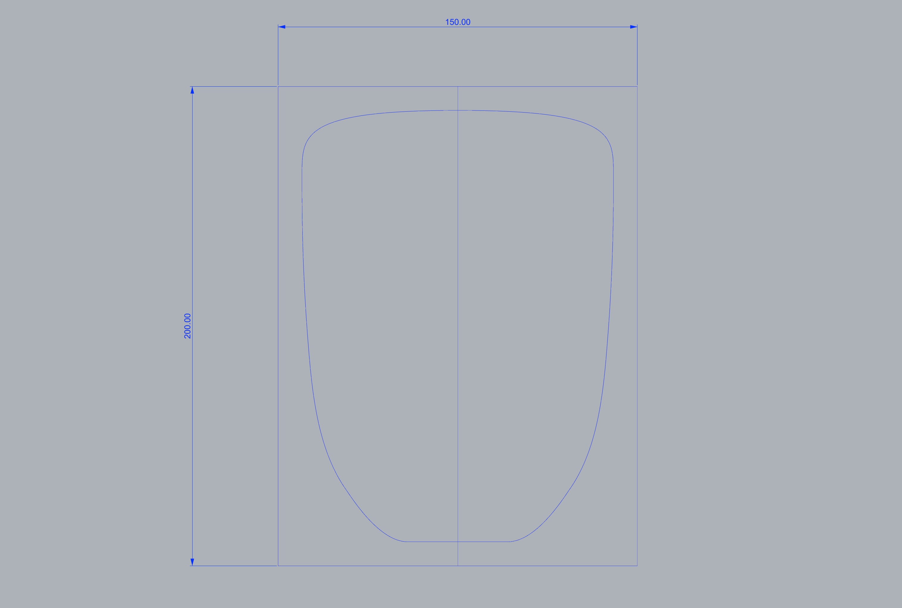
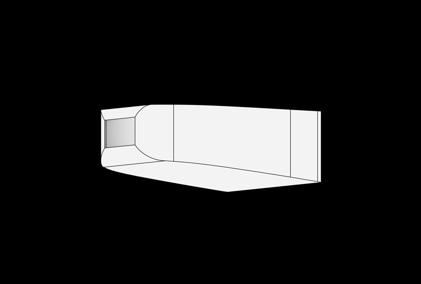
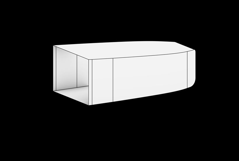
To construct the model, I started by drawing the top and side profile lines.
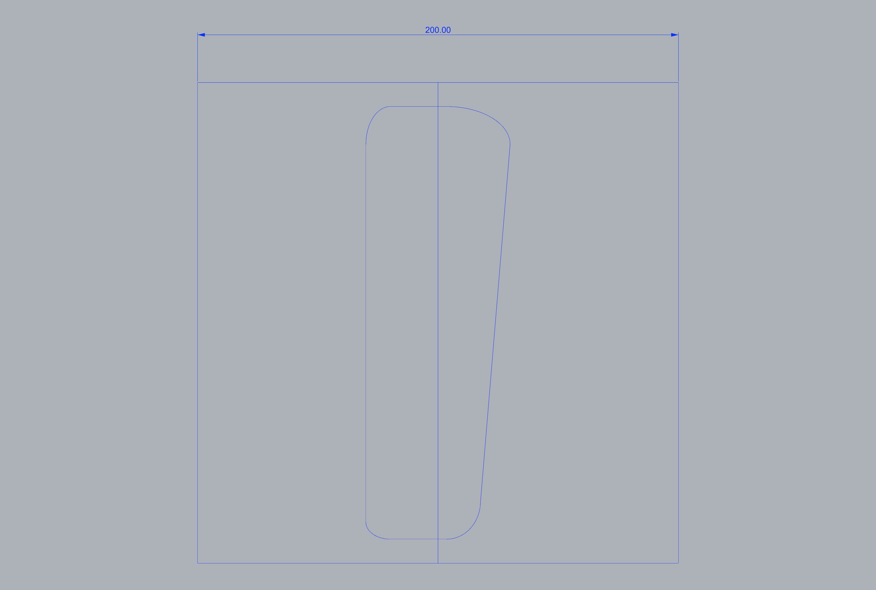
I then extruded the profile lines and executed a boolean difference to shape the top profile as drawn. Finally, I trimmed part of the model to remove unnecessary complex geometries. I was unsure if I could use simple surfaces to program the robots and thus used offsetsrf to add thickness to the model.
Outcome
Preping the Files for the Robot Arm
Installing the Robots Plugin
Rhino 7 now has an embedded Package Manager through which extensions for both Rhino and grasshopper can be installed. This tool can be accessed by typing packagemanager in Rhino’s command box, which brings out an interface. Form there, one can search for specific plugins and have them installed with a simple click.
The Grasshopper Robots plugin provides a toolset used to program ABB, Kuka, UR and Staubli Robots. I installed the plugin through Rhino’s package manager.

Alternatively, the plugin can be downloaded from its Github page, and installed by moving it to
/Users/”username”/Library/Application Support/McNeel/Rhinoceros/7.0/Plug-ins/Grasshopper/Libraries/
which can also be accessed by typing grasshopperfolders/components
Robot Library(ies)
It is essential to also install robot libraries before using the plugin. robot libraries can be found on the project’s github page. Their files are to be placed at the following location on MacOs
users/username/Documents/Robots
Setting the Workflow on Grasshopper
We were given an introductory class on 3D printing with 6-Axis Arm robots back in February. The class outlined a procedure to follow which is detailed below.
Select your robot model using the “Load robot” component.
Define your end effector (TCP, weight and geometry) using the “Create tool” component.
Create a flat list of targets that define your tool path using the “Create target” component.
Create a robot program connecting your list of targets and robot model to the “Create program” component.
Preview the tool path using the “Simulation” component.
Save the robot program to a file using the “Save program” component. If you’re using a UR robot, you can also use the “Remote UR” component to stream the program through a network.
We were also provided with the Grasshopper example file used for the class, which I have downloaded for this week from this link.
Printing the Structure
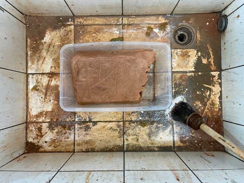
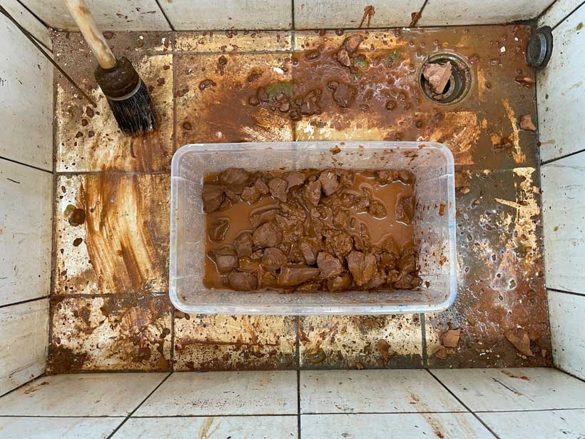
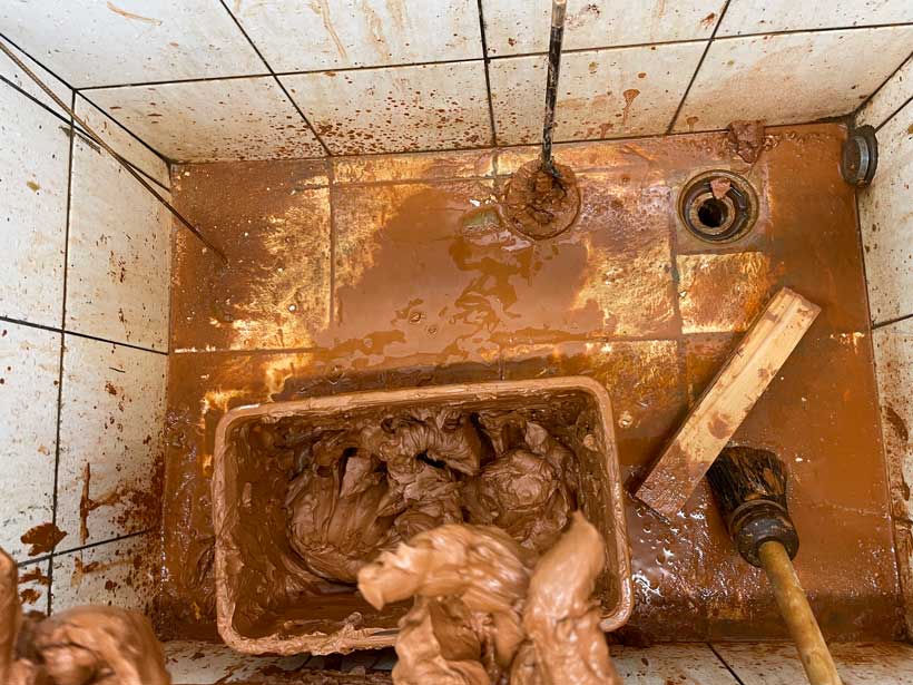
The Barcelona lab offered access to a variety of clays. For this assignment, I used the common brown clay. It needed to be mixed with water to become viscous and, in extension, be used as a printing material. I worked with other members of my class. We started from a large block of clay which we broke down into smaller chunks. We then added water and mixed both with our hands. The chunks were too large and took time to break down fully. We also added too much water, making the mix much more visquous than required for printing. We therefore used a hammer to ground additional blocks of clay and added the resulting clay powder to the initial mix.
Preparing the Batch of Material

Printing the Structure
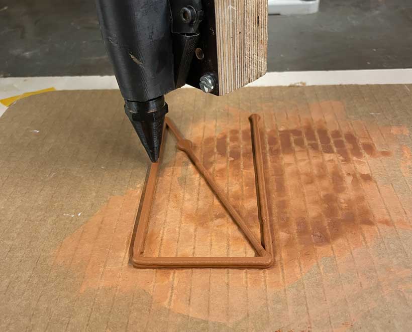
I haven’t taken pictures of the process by which files are loaded onto the robot arm. However, in short, the toolpath obtained from the grasshopper program was placed on a USB stick which was then connected to the the robot’s controller. From there, the file was loaded and the operation launched.

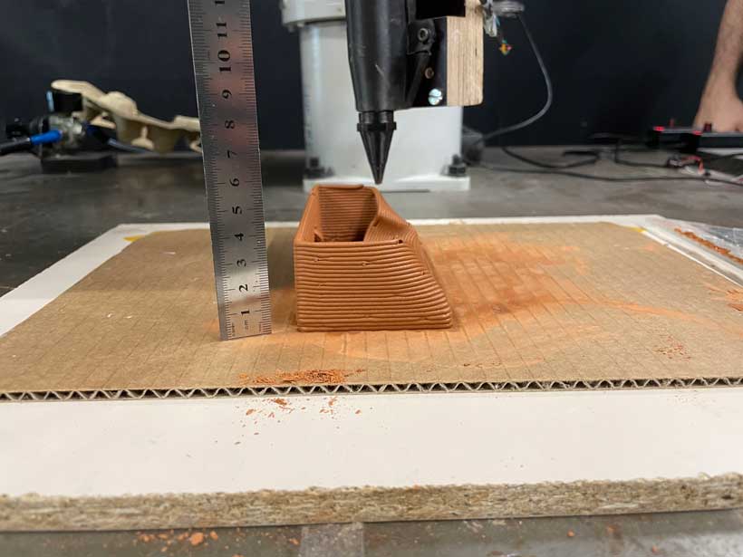
My first trial failed. The narrow base was unable to hold the weight of the upper layers and collapsed shortly after reaching the fourth or fifth layer.
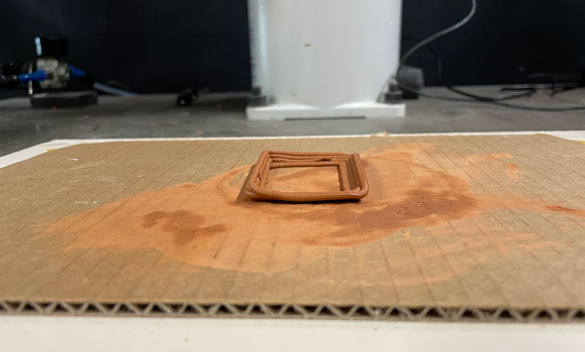
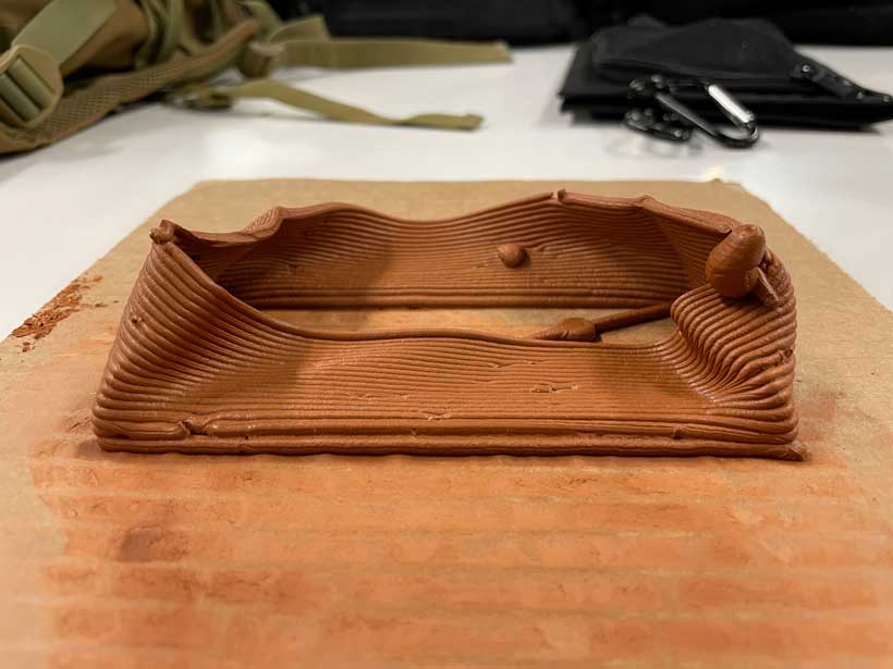
The second trial started well, even though one of the points on the toolpath was misaligned. However, the structure failed a quarter of the way through as itcollapsed on itself once it reached about 4 centimeters of height. There are multiple reasons that might explain why this happened. First, the clay batch we had produced was too liquid, hence limiting the integrity of printed structures. Second, the geometry I had designed was not optimal for clay printing. In fact, Edu explained that the straight walls and square corners are likely to have contributed to the collapse of the print. I believe it was a mixture of both that caused the model to fail.


I didn’t have enought time to modify the model and try again as our access to the robots was limited in time. To add insult to injury, the rest of the structure collapsed completely as I was moving it, pushing me further away from my objective.
Summary
Files
Week 15 Files