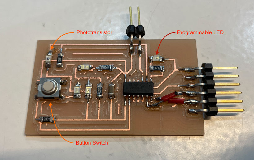
My plan for this week’s assignment was to program an interface that would interact with a switch, phototransistor and LED located on a board I had previously produced. I kept things simple as I didn’t have a lot of time to experiment.
I first focused on designing an interface containing a set number of elements whose characteristics would change when certain conditions are met. My aim was to define a programming logic for what I was aiming to achieve. With that goal in mind, I wrote a short program through which I would create a set number of boxes whose colour could be modified by clicking when the mouse pointer would be located within their boundaries.
import processing.serial.*;

Serial myPort;

// Initialisation of Variables used throughout.


int nBoxes = 3;

int canvasW = 1080; int canvasH = 1080;

int rectW = 400; int rectH = 200;

int rectX = 300; int rectY = 200; int Yoffset = 50;

int[] rectXcoordinates = new int[nBoxes];

int[] rectYcoordinates = new int[nBoxes];

boolean[] rectState = new boolean[nBoxes];

boolean[] rectHoverCondition = new boolean[nBoxes];

boolean clickedMouse = false;

String[] ButtonIndicators = {"LED Continuous", "LED Flicker", "Phototransistor"};


void setup() {
  size(1000,1080);
  background(248,248,255);
  noStroke();

    // List all the available serial ports
    // if using Processing 2.1 or later, use Serial.printArray()
    println(Serial.list());

    // I know that the first port in the serial list on my mac
    // is always my  Arduino, so I open Serial.list()[0].
    // Open whatever port is the one you're using.
    myPort = new Serial(this, Serial.list()[4], 9600);
    // don't generate a serialEvent() unless you get a newline character:
    myPort.bufferUntil('\n');

  for (int i = 0; i < nBoxes; i = i+1) {
    println(i);
    fill(0);
    rect(rectX,rectY,rectW,rectH,9);
    rectXcoordinates[i] = rectX;
    rectYcoordinates[i] = rectY;
    rectY += rectH + Yoffset;
  }
  println(rectXcoordinates);
}

void draw() {

    for (int j = 0; j < nBoxes; j = j+1){
      if ((mouseX>rectXcoordinates[j]) && (mouseX<(rectXcoordinates[j]+rectW)) && (mouseY>rectYcoordinates[j]) && (mouseY<(rectYcoordinates[j]+rectH)) && rectState[j] == false && clickedMouse == true){
        onState(rectXcoordinates[j], rectYcoordinates[j], ButtonIndicators[j]);
        rectState[j] = true;
        clickedMouse = false;
      }
      else if ((mouseX>rectXcoordinates[j]) && (mouseX<(rectXcoordinates[j]+rectW)) && (mouseY>rectYcoordinates[j]) && (mouseY<(rectYcoordinates[j]+rectH)) && rectState[j] == true && clickedMouse == true){
        offState(rectXcoordinates[j], rectYcoordinates[j],ButtonIndicators[j]);
        rectState[j] = false;
        clickedMouse = false;
      }
    }

}


void mouseClicked() {
  clickedMouse = !clickedMouse;
}


void onState(int x, int y, String ind){

      // Rectangle color modification.
      fill(128,237,153);
      rect(x,y,rectW,rectH,9);


      // Debugging.

      println("Debug - Mouse is Pressed in box - Switching to On");
      println("");
}

//
void offState(int x, int y, String ind){

      // Rectangle color modification.
      fill(0);
      rect(x,y,rectW,rectH,9);

      // Text related commands.


      // Debugging.

      println("Debug - Mouse is Pressed in box - Switching to Off");
      println("");
}
Using a tutorial by Sparkfun as reference, I worked on communicating commands between the Processing interface and an external PCB. I worked with a board I had produced for the Electronics Design week, which contained a button switch, a programmable LED and a phototransistor.
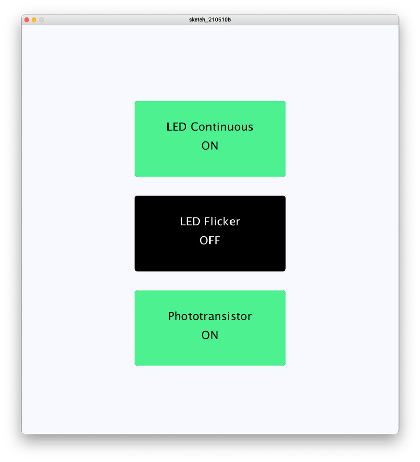
I added some text to the interface. Each button was now assigned a specific function I will later program into the board, and had an ON and OFF state. One would turn the LED on, the other would make it flicker, and the last would activate readings from the phototransistor. Should the phototransistor readings be activated, then the LED’s intensity would vary with the value emitted by the phototransistor. If they are deactivated, the LED’s intensity would be set to its highest value of 255.
Updated Interface with Descriptive Text
My aim was to use the button switch located on the board to set all buttons on the interface to their OFF state. Serial communication can be used to send/receive orders to/from a PCB. Processing has a pre-installed library designed for that specific purpose. I first had to initialise the library by going to Sketch/Import Library/Serial.
123
import processing.serial.*;

Serial myPort; // Create object from Serial class
Next, I had to specify which port to open through a specific command. To do so, I needed to obtain the name of all available ports, which I did using the following command:
1
println(Serial.list());
Using the below command, I initialised the serial port.
1
myPort = new Serial(this, "Port Name", Baud Rate);
Finally, I added a function which would constantly listen to the serial port and register a value sent by the board when the button is clicked. The Processing sketch responsible for the control of the interface was also modified to set all button states to off when a change in value occurred.
A simple if loop was added to the Arduino code I had written for the [Embedded Programming] week. This loop would send a “1” through the serial comm line when the board’s button was clicked. The complete Arduino and Processing programs can be found below.
// Pin Assignment
const int PuSwitchPin = 0; // PU Switch
const int LEDPin = 6; // LED
const int PTransPin = 7; // PhotoTransistor
// Initialisation of Variables
int PuSwState = 0;
int PuSwStatus = 0;
int PTransState = 0;
int LEDintensity = 0;
// the setup function runs once when you press reset or power the board
void setup() {
// initialize digital pin LED_BUILTIN as an output.
pinMode(LEDPin,OUTPUT);
// initialize digital pin Switch pin as an intput.
pinMode(PuSwitchPin, INPUT);
pinMode(PTransPin, INPUT);
Serial.begin(9600); //Initialising the serial monitor for debugging purposes
}
// the loop function runs over and over again forever
void loop() {
PuSwState = digitalRead(PuSwitchPin);
PTransState = analogRead(PTransPin);
if (PTransState > 0){
LEDintensity = map(PTransState, 0, 1023, 0, 255);
} else {
LEDintensity = 255;
}
analogWrite(LEDPin, LEDintensity);// turn the LED on (HIGH is the voltage level)
if (PuSwState == LOW){
Serial.println(1);
delay(500);
}
}
import processing.serial.*;
Serial myPort;
// Initialisation of Variables used throughout.
int nBoxes = 3;
int canvasW = 1080; int canvasH = 1080;
int rectW = 400; int rectH = 200;
int rectX = 300; int rectY = 200; int Yoffset = 50;
int[] rectXcoordinates = new int[nBoxes];
int[] rectYcoordinates = new int[nBoxes];
boolean[] rectState = new boolean[nBoxes];
boolean[] rectHoverCondition = new boolean[nBoxes];
boolean clickedMouse = false; boolean resetButton = false;
String[] ButtonIndicators = {"LED Continuous", "LED Flicker", "Phototransistor"};
void setup() {
size(1000,1080);
background(248,248,255);
noStroke();
// List all the available serial ports
// if using Processing 2.1 or later, use Serial.printArray()
println(Serial.list());
// I know that the first port in the serial list on my mac
// is always my Arduino, so I open Serial.list()[0].
// Open whatever port is the one you're using.
myPort = new Serial(this, "/dev/cu.usbserial-FT9P04G3", 9600);
// don't generate a serialEvent() unless you get a newline character:
myPort.bufferUntil('\n');
println(myPort);
for (int i = 0; i < nBoxes; i = i+1) {
println(i);
fill(0);
rect(rectX,rectY,rectW,rectH,9);
rectXcoordinates[i] = rectX;
rectYcoordinates[i] = rectY;
rectY += rectH + Yoffset;
}
println(rectXcoordinates);
}
void draw() {
if (resetButton == false){
offState(rectXcoordinates[0], rectYcoordinates[0],ButtonIndicators[0]);
rectState[0] = false;
offState(rectXcoordinates[1], rectYcoordinates[1],ButtonIndicators[1]);
rectState[1] = false;
offState(rectXcoordinates[2], rectYcoordinates[2],ButtonIndicators[2]);
rectState[2] = false;
resetButton = true;
}
for (int j = 0; j < nBoxes; j = j+1){
if ((mouseX>rectXcoordinates[j]) && (mouseX<(rectXcoordinates[j]+rectW)) && (mouseY>rectYcoordinates[j]) && (mouseY<(rectYcoordinates[j]+rectH)) && rectState[j] == false && clickedMouse == true){
onState(rectXcoordinates[j], rectYcoordinates[j], ButtonIndicators[j]);
rectState[j] = true;
clickedMouse = false;
} else if ((mouseX>rectXcoordinates[j]) && (mouseX<(rectXcoordinates[j]+rectW)) && (mouseY>rectYcoordinates[j]) && (mouseY<(rectYcoordinates[j]+rectH)) && rectState[j] == true && clickedMouse == true){
offState(rectXcoordinates[j], rectYcoordinates[j],ButtonIndicators[j]);
rectState[j] = false;
clickedMouse = false;
}
}
}
void serialEvent (Serial myPort) {
resetButton = boolean (myPort.readStringUntil ( '\n' ) ) ; // Changing
println(resetButton);
}
void mouseClicked() {
clickedMouse = !clickedMouse;
}
void onState(int x, int y, String ind){
// Rectangle color modification.
fill(128,237,153);
rect(x,y,rectW,rectH,9);
// Text related commands.
fill(0); // Text color.
textSize(30); // Font Size
textAlign(CENTER);
text(ind, x, y+rectH/4, rectW, rectH); // Text coordinates and contents.
text("ON", x, y+2*rectH/4, rectW, rectH); // Text coordinates and contents.
// Debugging.
println("Debug - Mouse is Pressed in box - Switching to On");
println("");
}
//
void offState(int x, int y, String ind){
// Rectangle color modification.
fill(0);
rect(x,y,rectW,rectH,9);
// Text related commands.
fill(255); // Text color.
textSize(30); // Font Size
textAlign(CENTER);
text(ind, x, y+rectH/4, rectW, rectH); // Text coordinates and contents.
text("OFF", x, y+2*rectH/4, rectW, rectH); // Text coordinates and contents.
// Debugging.
println("Debug - Mouse is Pressed in box - Switching to Off");
println("");
}
Finally, I added a few commands to both the Arduino and the processing programs in order to control the PCB from the interface, as demonstrated below.
In short, the exchange of commands is achieved through UART commms. When either Processing or the PCB receive data on the Serial lines, this data is read and interpreted. The section above detailed how commands are sent from the PCB to the processing interface. For sending commands from the interface to the PCB I derived a simple logic in which a specific value would be sent to the board when one of the interface buttons was clicked. This value would inform the PCB of the current state of the interface buttons, which would in turn triger a change of state in the LED or phototransistor, as decribed in the below table.
// Pin Assignment
const int PuSwitchPin = 0; // PU Switch
const int LEDPin = 6; // LED
const int PTransPin = 7; // PhotoTransistor
// Initialisation of Variables
int PuSwState = 0;
int PuSwStatus = 0;
int PTransState = 0;
int LEDintensity = 0;
int val = 0;
// the setup function runs once when you press reset or power the board
void setup() {
// initialize digital pin LED_BUILTIN as an output.
pinMode(LEDPin,OUTPUT);
// initialize digital pin Switch pin as an intput.
pinMode(PuSwitchPin, INPUT);
pinMode(PTransPin, INPUT);
Serial.begin(9600); //Initialising the serial monitor for debugging purposes
}
// the loop function runs over and over again forever
void loop() {
PuSwState = digitalRead(PuSwitchPin);
if (Serial.available()) { // If data is available to read,
val = Serial.read(); // read it and store it in val
}
if (val == 0){
PTransState = 0;
LEDintensity = 0;
} else if(val == 1){
PTransState = analogRead(PTransPin);
LEDintensity = map(PTransState, 0, 1023, 0, 255);
} else if(val == 2){
PTransState = 1;
LEDintensity = 255;
} else if(val == 3){
PTransState = analogRead(PTransPin);
LEDintensity = 0;
}
analogWrite(LEDPin, LEDintensity);// turn the LED on (HIGH is the voltage level)
if (PuSwState == LOW){
Serial.println(1);
delay(500);
}
}
import processing.serial.*;
Serial myPort;
// Initialisation of Variables used throughout.
int nBoxes = 2;
int canvasW = 1080; int canvasH = 1080;
int rectW = 400; int rectH = 200;
int rectX = 300; int rectY = 200; int Yoffset = 50;
int[] rectXcoordinates = new int[nBoxes]; int[] rectYcoordinates = new int[nBoxes];
int[] rectState = new int[nBoxes];
boolean[] rectHoverCondition = new boolean[nBoxes]; boolean clickedMouse = false;
boolean resetButton = false;
String[] ButtonIndicators = {"LED Continuous", "Phototransistor", "LED Flicker"};
void setup() {
size(1000,1080);
background(248,248,255);
noStroke();
// List all the available serial ports
// if using Processing 2.1 or later, use Serial.printArray()
println(Serial.list());
// I know that the first port in the serial list on my mac
// is always my Arduino, so I open Serial.list()[0].
// Open whatever port is the one you're using.
myPort = new Serial(this, "/dev/cu.usbserial-FT9P04G3", 9600);
// don't generate a serialEvent() unless you get a newline character:
myPort.bufferUntil('\n');
println(myPort);
for (int i = 0; i < nBoxes; i = i+1) {
println(i);
fill(0);
rect(rectX,rectY,rectW,rectH,9);
rectXcoordinates[i] = rectX;
rectYcoordinates[i] = rectY;
rectY += rectH + Yoffset;
}
println(rectXcoordinates);
}
void draw() {
if (resetButton == false){
for (int i = 0; i < nBoxes; i = i+1){
offState(rectXcoordinates[i], rectYcoordinates[i],ButtonIndicators[i]);
rectState[i] = 0;
}
resetButton = true;
}
for (int j = 0; j < nBoxes; j = j+1){
if ((mouseX>rectXcoordinates[j]) && (mouseX<(rectXcoordinates[j]+rectW)) && (mouseY>rectYcoordinates[j]) && (mouseY<(rectYcoordinates[j]+rectH)) && rectState[j] == 0 && clickedMouse == true){
onState(rectXcoordinates[j], rectYcoordinates[j], ButtonIndicators[j]);
rectState[j] = 1;
clickedMouse = false;
} else if ((mouseX>rectXcoordinates[j]) && (mouseX<(rectXcoordinates[j]+rectW)) && (mouseY>rectYcoordinates[j]) && (mouseY<(rectYcoordinates[j]+rectH)) && rectState[j] == 1 && clickedMouse == true){
offState(rectXcoordinates[j], rectYcoordinates[j],ButtonIndicators[j]);
rectState[j] = 0;
clickedMouse = false;
}
}
// Sending commands to Arduino
if(rectState[0] == 0 && rectState[1] == 0){
myPort.write(0);
}else if(rectState[0] == 1 && rectState[1] == 1){
myPort.write(1);
}else if(rectState[0] == 1 && rectState[1] == 0){
myPort.write(2);
}else {
myPort.write(3);
}
}
void serialEvent (Serial myPort) {
  resetButton = boolean (myPort.readStringUntil ( '\n' ) ) ;  // Changing
}
void mouseClicked() {
clickedMouse = !clickedMouse;
}
void onState(int x, int y, String ind){
// Rectangle color modification.
fill(128,237,153);
rect(x,y,rectW,rectH,9);
// Text related commands.
fill(0); // Text color.
textSize(30); // Font Size
textAlign(CENTER);
text(ind, x, y+rectH/4, rectW, rectH); // Text coordinates and contents.
text("ON", x, y+2*rectH/4, rectW, rectH); // Text coordinates and contents.
// Debugging.
println("Debug - Mouse is Pressed in box - Switching to On");
println("");
}
//
void offState(int x, int y, String ind){
// Rectangle color modification.
fill(0);
rect(x,y,rectW,rectH,9);
// Text related commands.
fill(255); // Text color.
textSize(30); // Font Size
textAlign(CENTER);
text(ind, x, y+rectH/4, rectW, rectH); // Text coordinates and contents.
text("OFF", x, y+2*rectH/4, rectW, rectH); // Text coordinates and contents.
// Debugging.
println("Debug - Mouse is Pressed in box - Switching to Off");
println("");
}
I was very limited in time this week and didn’t have time to learn to use Node-Red. However, I am definitely interested in determining how it can be used in a remote network to control the flow of data and display relevant information, when desired to a user. I’ll try to do this after the project presentations.
I essentially tried to create an app that would Post data from my phone to the ESP web server I programmed on an ESP32 during the Networking and Communications week. Should I succeed, I would then be able to broadcast my phone’s GPS coordinates to my final project’s base station, and essentially track my phone instead of a module designed separately. I succeeded.
Processing is described as being “a graphical library and development environmnet designed for teaching non-programmers the fundementals of computer programming in a visual context”. Its language is built around Java, to which it adds additional simplifications through aliases, mathematical functions and operations.
Processing’s own interface is almost identical to that of the Arduino IDE. This made it a quite familiar environment to work in and rather easy to pick up.
The structure of the language itself is also similar to that of Arduino. Variable definition, library imports, function definition and logic functions work in the same manner. Further to this, processing can work with Serial ports to send and receive commands or data which allows for external components to control and interface, or be controlled by an interface.
From my experience using it, I must say that it does achieve its principal goal rather well. The framework does not feel limiting for simple implementations, and the community resources make it even more accessible. However, I am not in a position to say how efficient it might be to use in order to deploy more complex visual interfaces.
This tool is impressive in its simplicity. First of all, the interface itself is well designed as it allows for specific elements to be added easily through its “designer” module. Second, manipulating on screen elements