8. Embedded Programming
Disclaimer
I left my board at the lab and I had to stay home throughout the duraiton of the embedded programming cycle as I had caught a cold. I therefore used tinkercad’s arduino simulator to test out the codes I had planned to use. I
8.1. Individual Assignment
A. Reading a datasheet - ATtiny1614
The datasheet of any microprocessor is like a maze of information taken straight out of a nightmare, specially for someone with the attention level of a tea spoon. Furtermore, this information spreads across a large range of concepts of electronics and can become an obstacle to the laymen.
For this assignment, I have scrolled through the datasheet of the microprocessor I used for my PCB; the ATtiny 1614; and identified the information that is relevant to the work to be carried out for this week.
Electrical Characteristics
Details the voltage, current and temperature value ranges for optimal operation. This section also lists the power consumption of the processor and its peripherals under different contexts. Finally, here, one can also find programming and boot times.
Memories
This section specifies the properties of the different types of memories featured on the board such as their size and hex addresses. Moreover, information regarding the fuses can also be obtained here.
Package Drawings
Provides information regarding the processor’s packaging, namely dimensions and thermal considerations. This is important in determining if a packaging will offer the desired protection from its environment while respecting the spatial constraints.
Peripherals & Architecture
This section lists the base addresses of all peripheral modules (ports, configurators, controllers, timers …) and interrupt vectors. It also features diagrams of the board’s architecture.
Pinout
The pinout section of the datasheet describes the information required to determine how to interact with the processor. It lists the function of each pin, their reference and the types of compatible signals. Below is a diagram that shows the aforementioned information for the ATtiny1614.
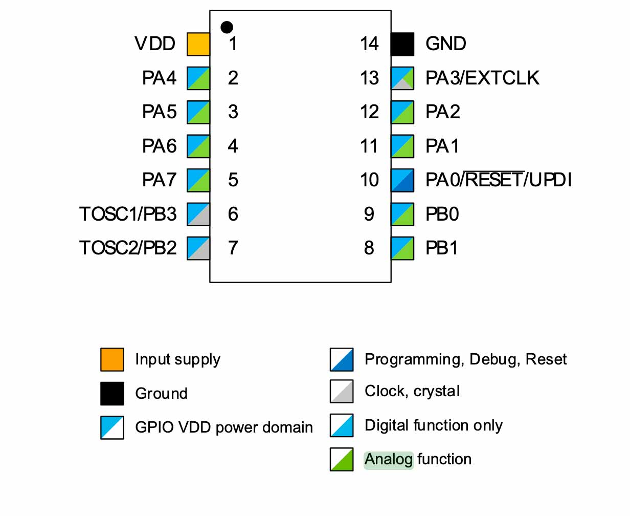
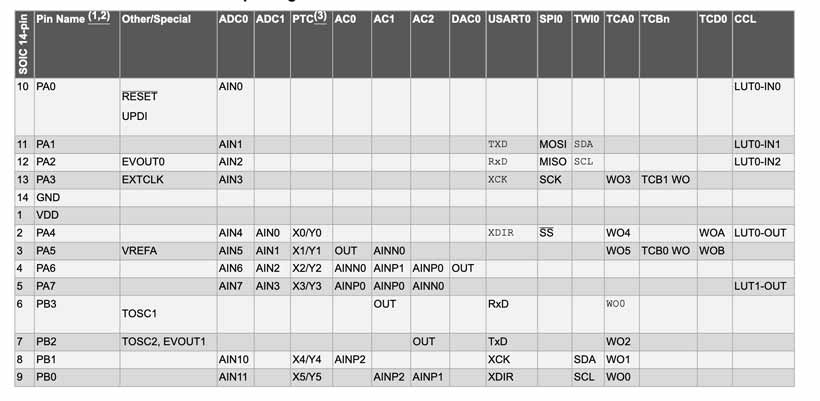

Pin Table
| Pin Name | Pin Number | Description |
|---|---|---|
| VCC | NA | Input Power Supply |
| GND | NA | Ground |
| SS | 0 | SPI Interface - Slave Select |
| VREF | 1 | Reference Voltage |
| DAC | 2 | Digital to Analog Converter |
| X OUT | 3 | |
| RxD | 4 | Data Reception Line |
| TxD | 5 | Data Transmission Line |
| SDA | 6 | I2C physical Bus - Serial Data Line |
| SCL | 7 | I2C physical Bus - Serial Clock Line |
| MOSI | 8 | SPI Interface - Master Out Slave In |
| MISO | 9 | SPI Interface - Master In Slave Out |
| SCK | 10 | SPI Interface - Serial Clock |
| UPDI | 11 | Unified Programming and Debug Interface |
| - | - | - |
| Pin Type | Pin Number | Description |
| PAx | 0-1-2-3-8-9-10-11 | Port A pins - 8 Bits |
| PBx | 4-5-6-7 | Port B pins - 16 bits |
Link to datasheet
*ATtiny1614 data table
Using the above, I compiled a table containing the relevant characteristics of the ATtiny1614.
| CPU Type | AVR |
| CPU Size | 8 bits |
| CPU Architecture | Harvard |
| CPU Speed | 20MHz |
| Number of I/O Lines | 16 |
| Programmable I/O Lines | 14 |
| Programmable Memory Type | Flash |
| Programmable Memory Size | 16k Bytes |
| EPROM Size | 265 Bytes |
| SRAM Size | 2k Bytes |
| Peripherals | AC, ADC, DAC, PTC, RTC, TWI(I2C), USART |
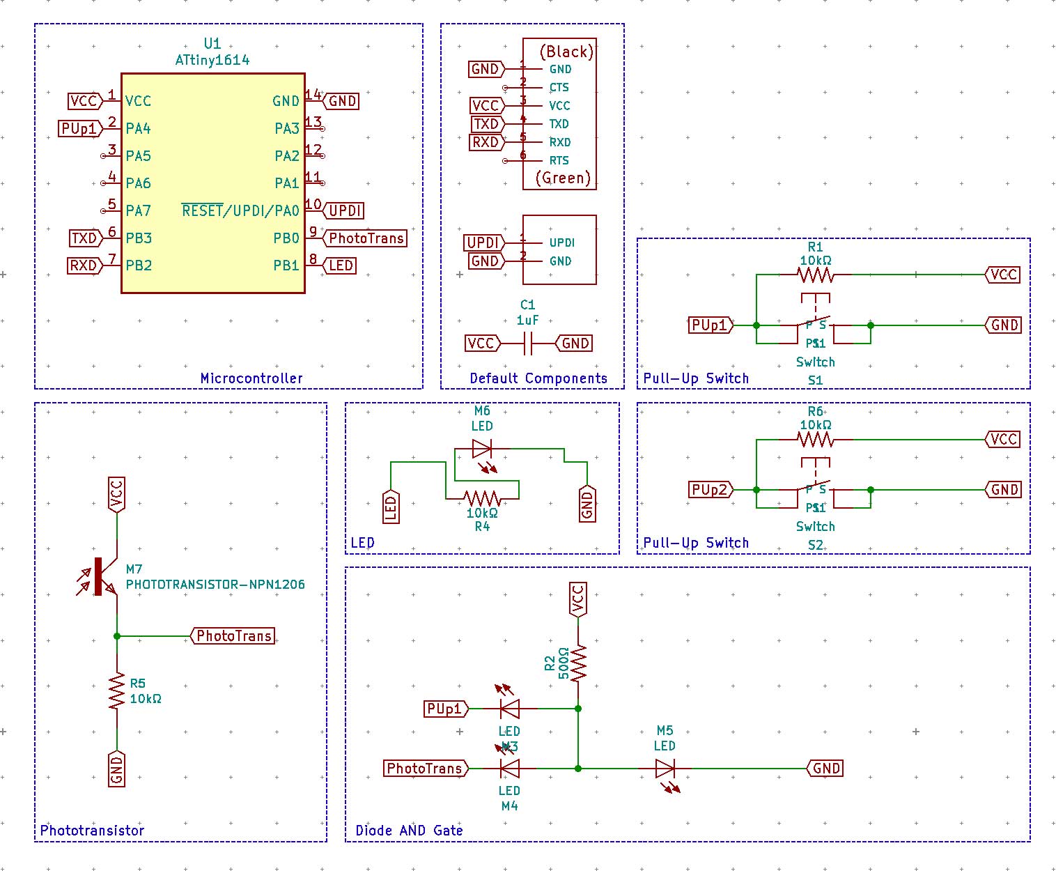
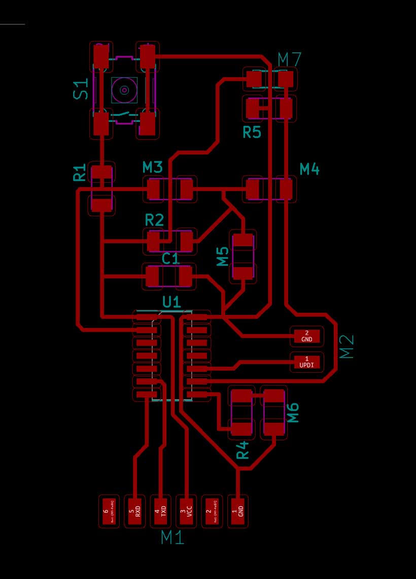
B. Week 06 PCB Design Update
As mentioned in the sixth week’s documentation page, the board I had produced for the Electronics Design cycle did not work as intended. The main issue was that its logic gate circuit was not well thought out. As such, I have decided to update its design before moving forward with the rest of the assignment.
First of all, I had not checked the ATtiny 1614’s internal pin assignments. It was brought to my attention that I might have improperly connected the RxD and TxD pins as their location was not specified on the Kicad schematics, in which case it would be impossible to program the board through serial communication. As mentioned above, pin assignments can be obtained form the processors pin-out diagram, itself located in the unit’s datasheet. One thing to note regarding the data transmission pins is that the RxD (Data Reception) pins must be connected to the TxD (Data Transmission) pins of the opposing device, and vice versa.
The LED was already connected to a PWM pin.
Summary of changes made to the original PCB Design
- Corrected RxD/TxD pin connections.
- Replaced VCC input in logic gate with Photo Transistor output and arranged layout accordingly
- Removed an unnecessary resistor in the Diode logic gate.
Notes from the re-design
- Connect TxD pin of device transmitting data to the RxD pin of the device receiving device.
C. Programming the board
As mentioned earlier, I wasn’t able to go to the lab during this cycle. I also didn’t have enough time afterwards to produce the corrected board. I therefore programmed the board I had made for Week 6. The improper UART Pin configuration wasn’t be an issue as I was be programming the board through UPDI. However, I still corrected the connection using soldered jumper cables.
Arduino IDE
Setting up the Workflow
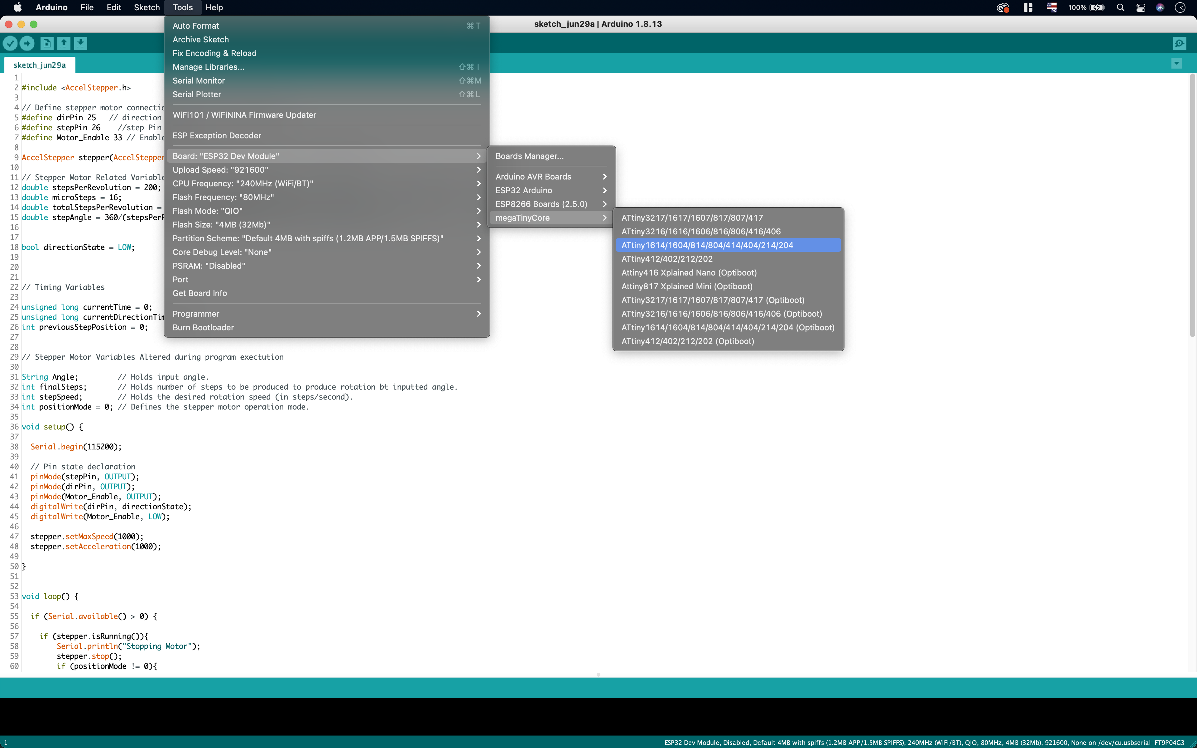
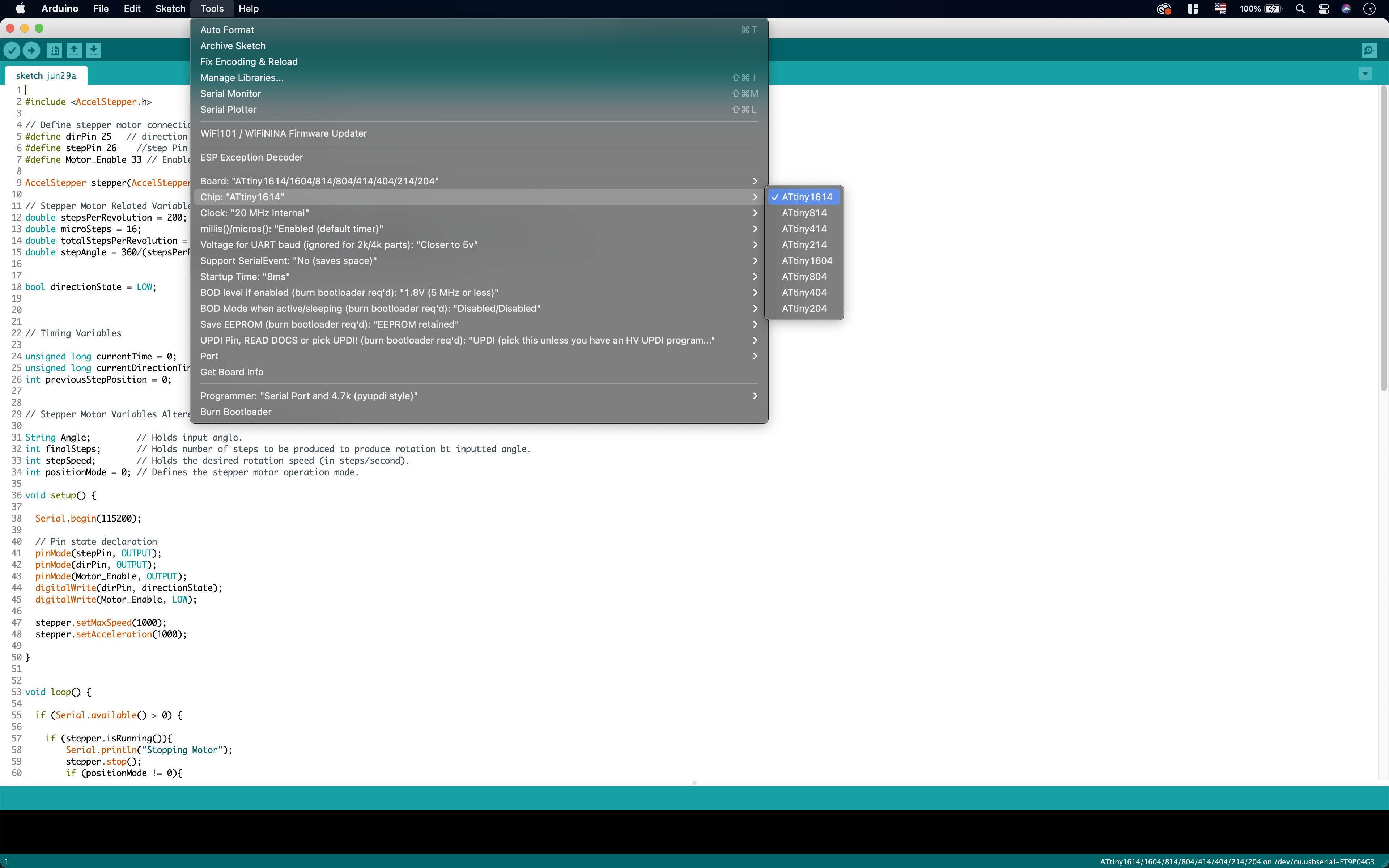
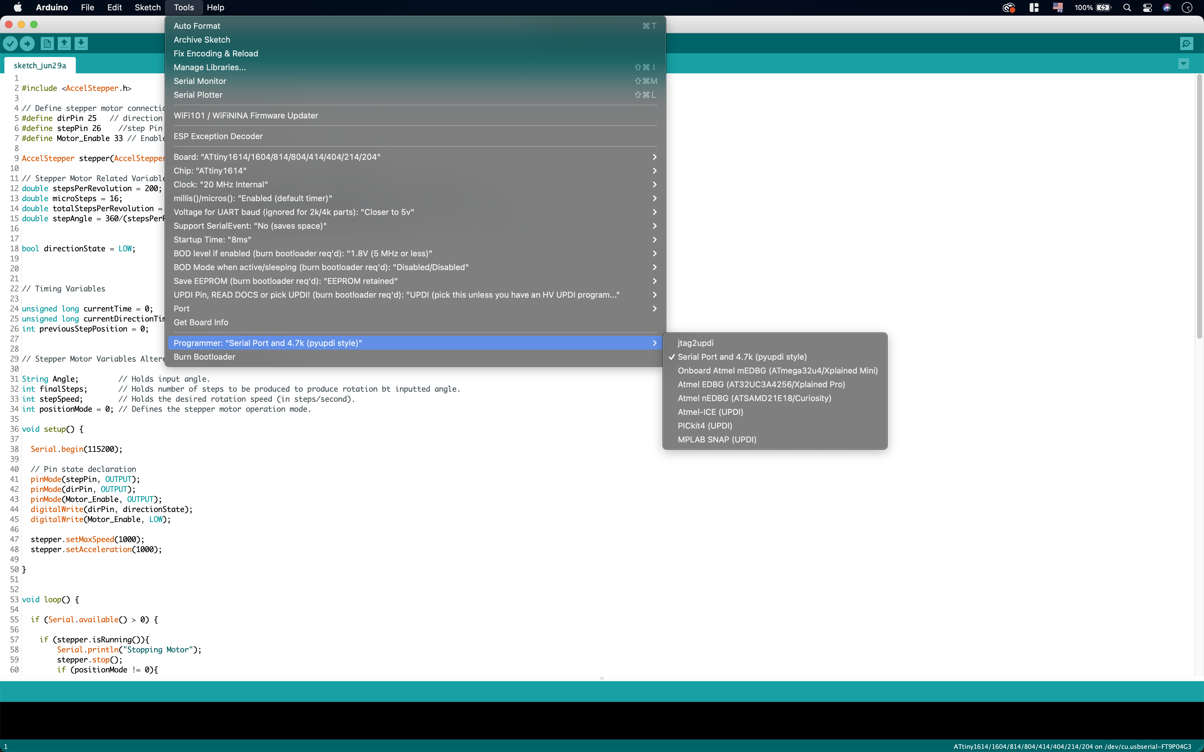
I only used Arduino IDE. I first had to install the ATtiny board library (megatinycore) in order to interract with ATT1614 I had installed. To do so, I followed the steps outlined on the megaTinyCore library’s github page. Once installed, I needed to select the board and programming sketch to be used in:
Tools / Board / megaTinyCore / ATtiny1614.....
&
Tools / Chip / ATtiny1614
&
Tools / Programmer / SerialPort & 4.7k (pyUPDI Style)
Blink
The following LED Blink program sketches were given to us in class as examples.
1 2 3 4 5 6 7 8 9 10 11 12 13 14 15 | |
The compiled sketch weighs 930 bytes as described by the below message, discplayed upon a successful compilation.
Sketch uses 930 bytes (5%) of program storage space. Maximum is 15872 bytes. Global variables use 10 bytes (0%) of dynamic memory, leaving 2038 bytes for local variables. Maximum is 2048 bytes.
1 2 3 4 5 6 7 8 9 10 11 12 13 14 15 16 17 | |
1 2 3 4 5 6 7 8 9 10 11 12 13 14 15 16 17 18 19 20 21 22 23 24 25 26 | |
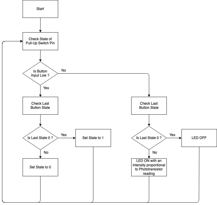
Building from these, I developed a program of my own that also considers the other components (button and phototransistor) present on my board. The idea is rather simple. The button acts similarly to a wall lamp switch. If the button is pressed once, the LED is turned on at an intensity proportional to that detected by the phototransistor. If it is pressed again, the LED is switched off. By default, the LED is set to be off.
1 2 3 4 5 6 7 8 9 10 11 12 13 14 15 16 17 18 19 20 21 22 23 24 25 26 27 28 29 30 31 32 33 34 35 36 37 38 39 40 41 42 43 44 45 46 47 | |
TinkerCAD Simulation
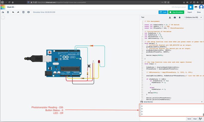
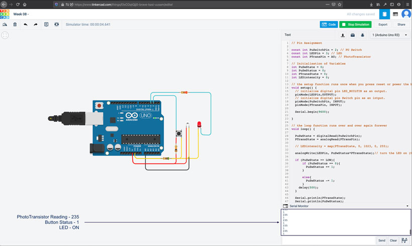
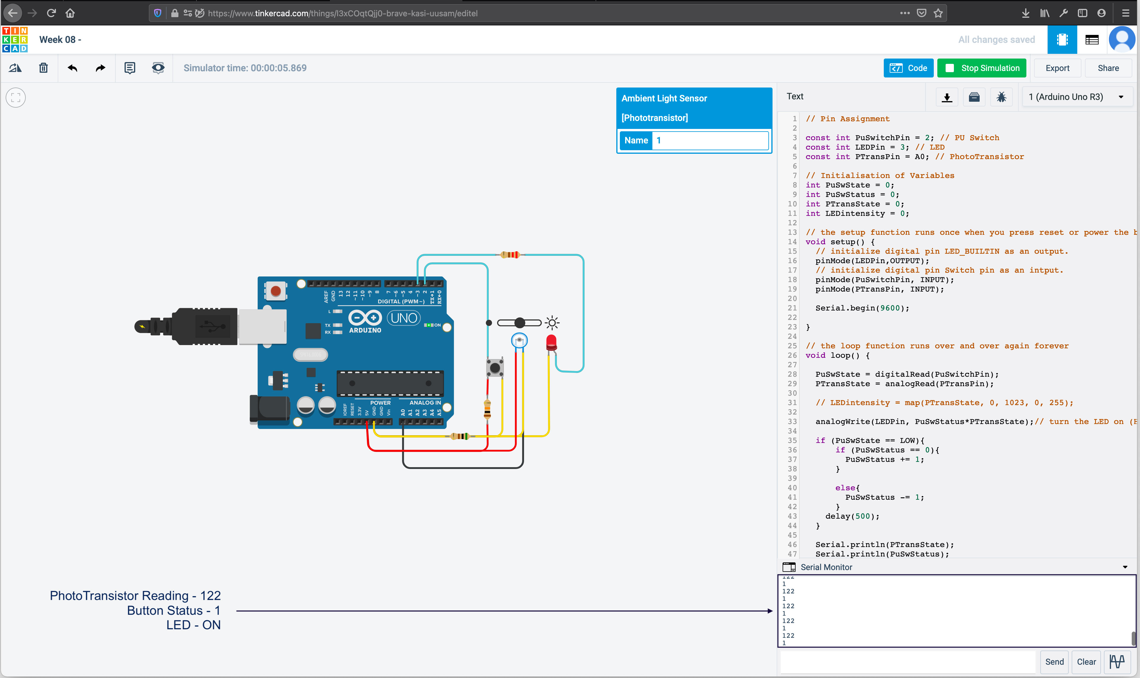
Being unable to use my personal board, I couldn’t test the code I had written. I therefore used Tinkercad’s circuit simulation module by recreating part of my board’s circuit.

Arduino
I uploaded the Arduino C program shown above through the Arduino IDE. The upload configurations used are shown in the below screenshot.
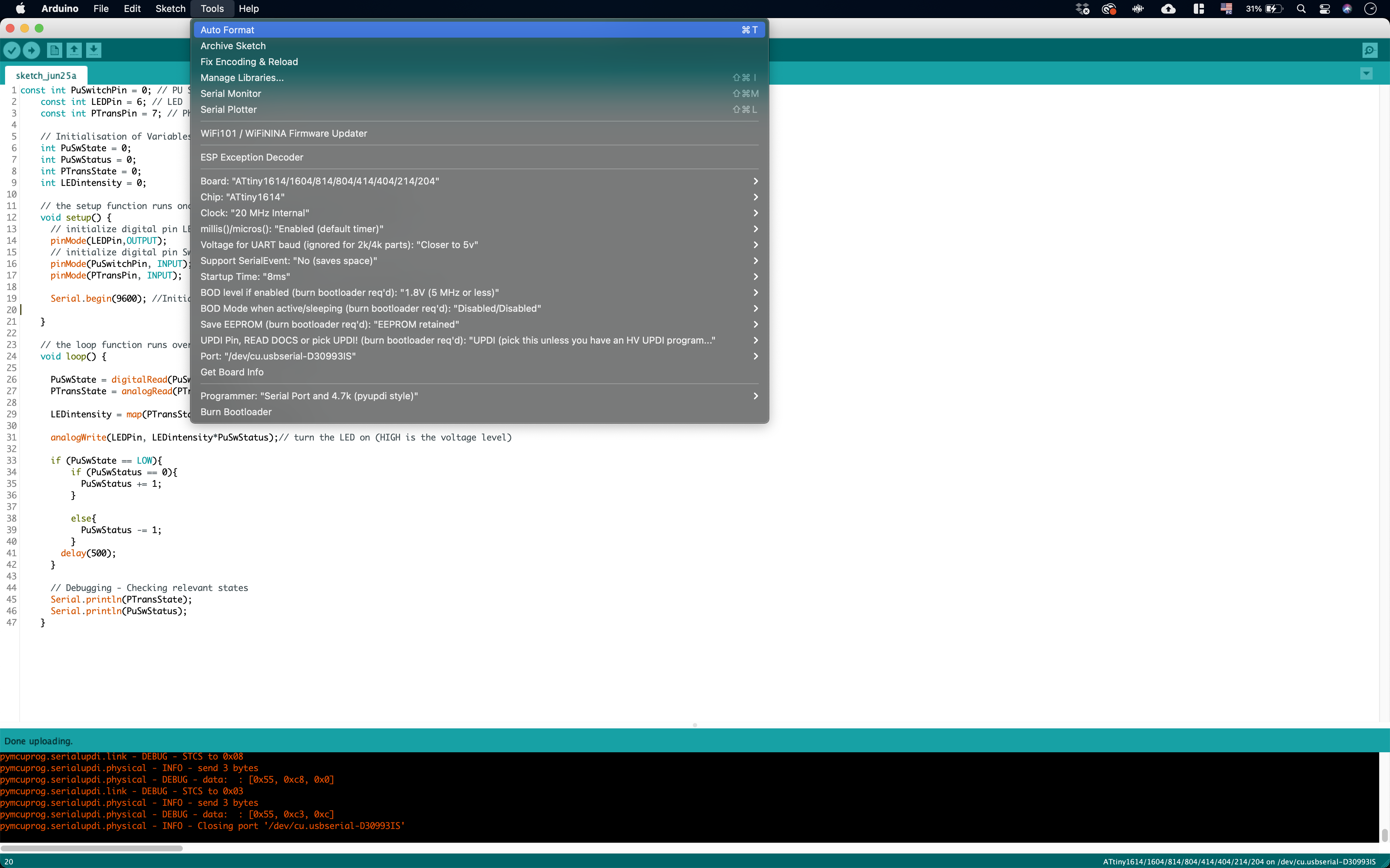
Arduino IDE upload configuration for ATtiny1614Once completed, I tested the board by turning the LED on using the button switch, and using a flashlight to alter the phototransistor readings. Worked like a charm !
Board Testing8.2. Group Assignment
Please refer to Carla’s extensive documentation of the work carried out for the group assignment.
8.3. Class Notes
A. Common Terms
| Term | Definition |
|---|---|
| Discrete | Taking on or having a finite or countably infinite number of values. |
| Silicone Photonics | Study and application of photonic systems which use silicon as an optical medium. The silicon is usually patterned with sub-micrometre precision, into microphotonic components. |
| Embedded Systems | According to OmniSci, embedded systems are microprocessor-based computer hardware systems with software that is designed to perform a dedicated function, either as an independent system or as a part of a large system. At the core is an integrated circuit designed to carry out computation for real-time operations. Complexities range from a single microcontroller to a suite of processors with connected peripherals and networks; from no user interface to complex graphical user interfaces. The complexity of an embedded system varies significantly depending on the task for which it is dsesigned. Embedded system applications range from digital watches and microwaves to hybrid vehicles and avionics. As much as 98 percent of all microprocessors manufactured are used in embedded systems. |
| Architecture | The architecture of an embedded system defines the roles and interactions of the different types of hardware and software components within the system. 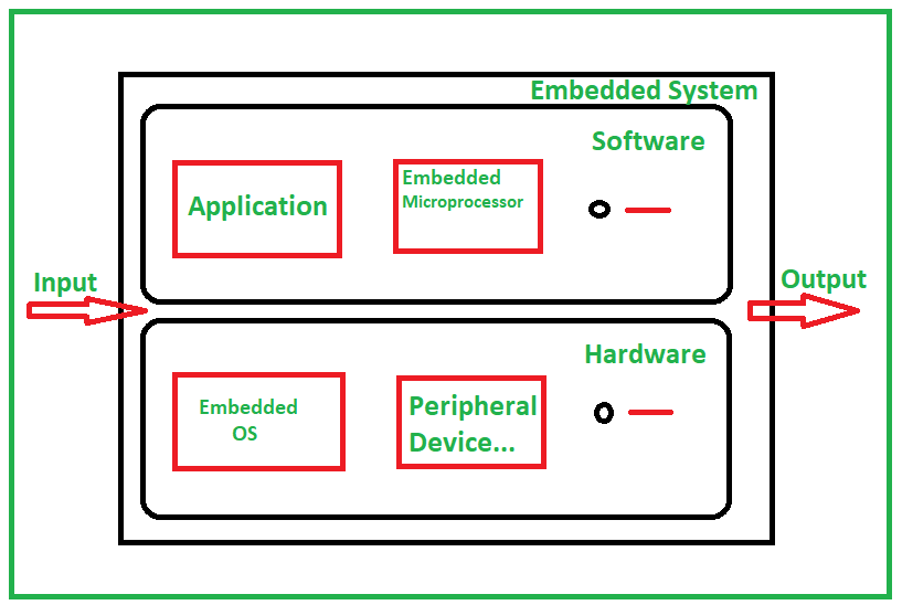 |
| Development Platform | Set of standards that enable developers to develop software applications based on the right technology stack. |
| Development Framework | An abstraction in which software providing generic functionality can be selectively changed by additional user-written code, thus providing application-specific software. It provides a standard way to build and deploy applications and is a universal, reusable software environment that provides particular functionality as part of a larger software platform to facilitate the development of software applications, products and solutions. Software frameworks may include support programs, compilers, code libraries, toolsets, and application programming interfaces (APIs) that bring together all the different components to enable development of a project or system. |
| Toolchain | Set of programming tools that are used to perform a complex software development task or to create a software product, which is typically another computer program or a set of related programs |
| Compiler | Comouter program that translates a code written in one programming language (source language) into another (target language) to produce an executable program. This is generally done from a language with a high level of abstraction (C, C++, Java …) to one with a low level of abstraction (Assembly, Machine code, object code, or pure binary) |
| Abstraction |
B. Harvard vs Von Neumann Architectures
(https://www.microcontrollertips.com/difference-between-von-neumann-and-harvard-architectures/)
(https://www.geeksforgeeks.org/difference-between-computer-and-embedded-system/)
C. Programming in Arduino IDE - Syntax Rules
// Commented text is preceded by two slashes (//)

// Syntax Rules ___________________________________________________________________________________________________________________________________________________________________


// 1. Colons ; mark the end of a command;
// 2. {Brackets outline the contents of a function/loop};
// 3. (Parentheses contain definitions and conditions for functions);
// 4. Syntax is case SENSITIVE. This depends on the command;


// Variably types ___________________________________________________________________________________________________________________________________________________________________

int integer = whole number;
float decimal = numbers with decimals;
bool boolean_number = Can only hold two values : True or False (1 or 0);

char string = initialises a variable as a string, whatever its content;

// Commands ___________________________________________________________________________________________________________________________________________________________________

delay(x milliseconds); // Waits for the specified amount of time before moving on.

digitalRead(Pin);  // Reads the logic state of a pin - Can determine if input voltage is high (1) or low (0).
analogRead(Pin);   // Reads the value from an analog pin.


void setup() {

    // Initialise pins, functions ....

    // Runs once after startup

    pinMode(pinnumber, INPUT); // Setting pin as an Input: Receives data from external component
    pinMode(pinnumber, OUTPUT); // Setting pin as an Input: Sends data from external component
}

void loop() {

  // Main program

  // Runs as long as the system has power
}