Networking and Communications
Assignment List
- individual assignment ☐
- design, build, and connect wired or wireless node(s) with network or bus addresses ☐
- group assignment ☐
- send a message between two projects ☐
- To Conclude & Reflect
Individual Assignment: The rn4871
Testing the rn4871 bluetooth I had little succes, however I did stumble upon some jucy sources to actully get it to work
My advide to future self is: try the hc-05 first and once you know how things should work try the rn4871.
Advantages of this module are the low power option, and the 4.0 connectivity that is compatible with among other things iphones and other newer devices, even hide itself to the untrained bluetooth.
The process: In this case, before actually ever using bluetooh, I was confident, enough to create two pcb fully certain they would work with the BT.
I include the input/output pcb's just because the direct debbuging that ocurred was with the bluetooth. I also wish to leave all the links to buld upon failures.
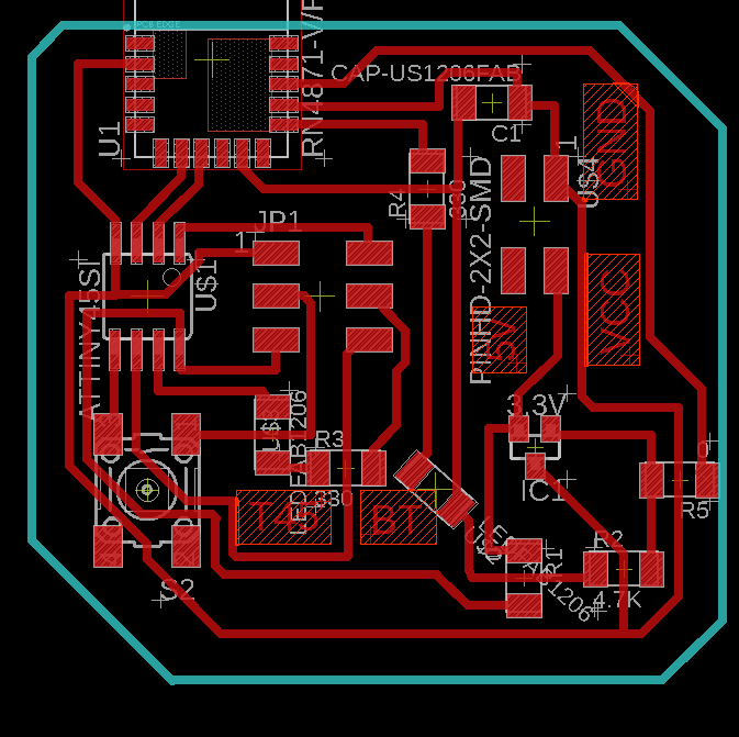
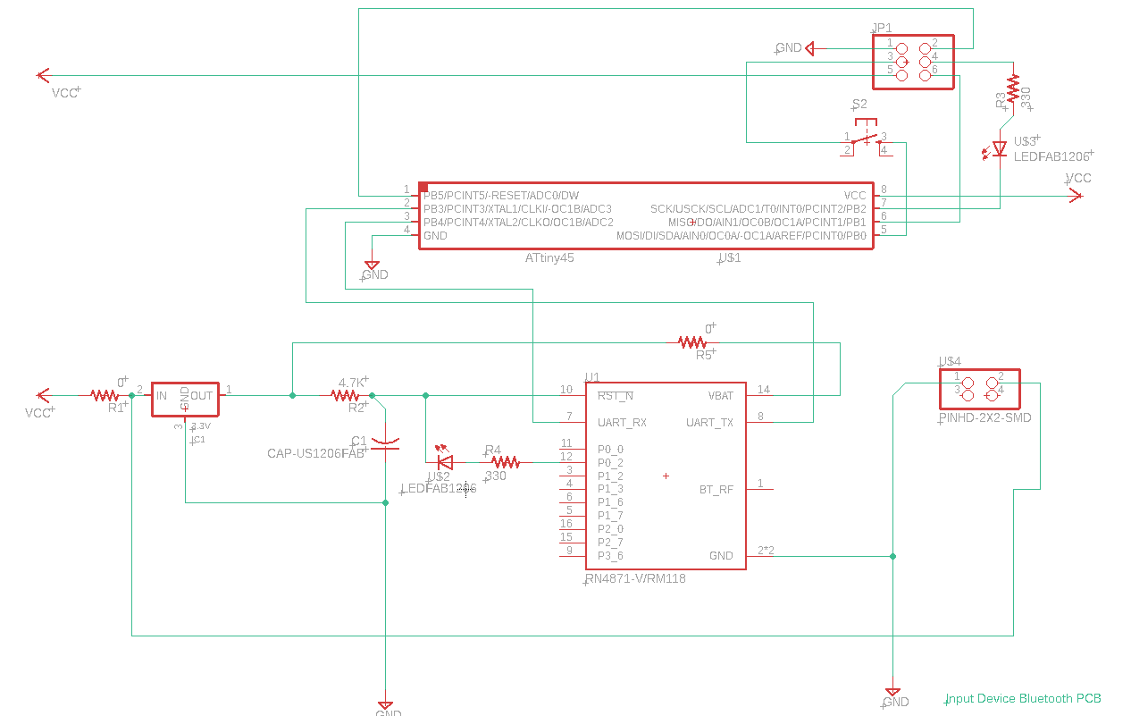
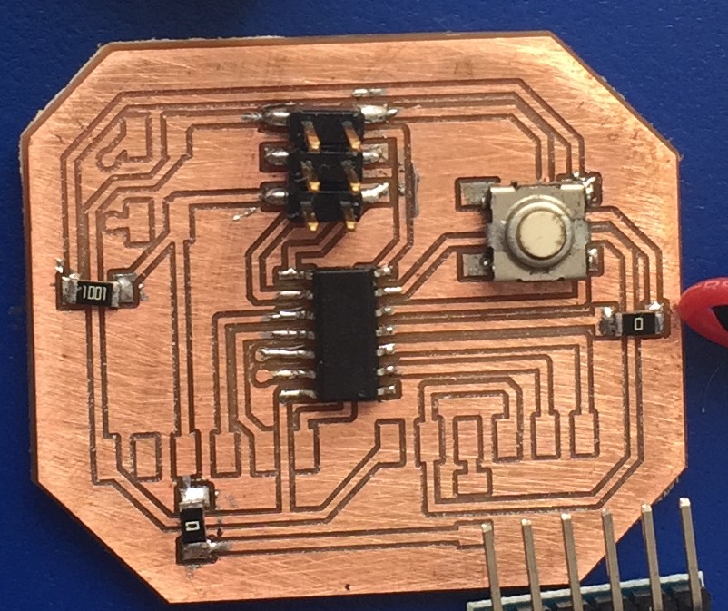
Input PCB: (week 11)
BOM:
| Quantity | Component |
|---|---|
| 1 | Attiny 44 |
| 1 | RN4871 Bluetooth module |
| 1 | Button 6mm |
| 2 | LED Light SMD |
| 1 | Capacitior 1 uf |
| 1 | 2x3 pin ISP connector, male |
| 1 | 2x2 pin connector, male |
| 2 | 330 ohm Resistance |
| 2 | 0 ohm Resistance |
| 1 | 3.3 v IC |
| 1 | 4.7 k Resistance |
Debugging
In this case, I figured out later on that the bluetooth vcc was not connected and I required to jump a cable.
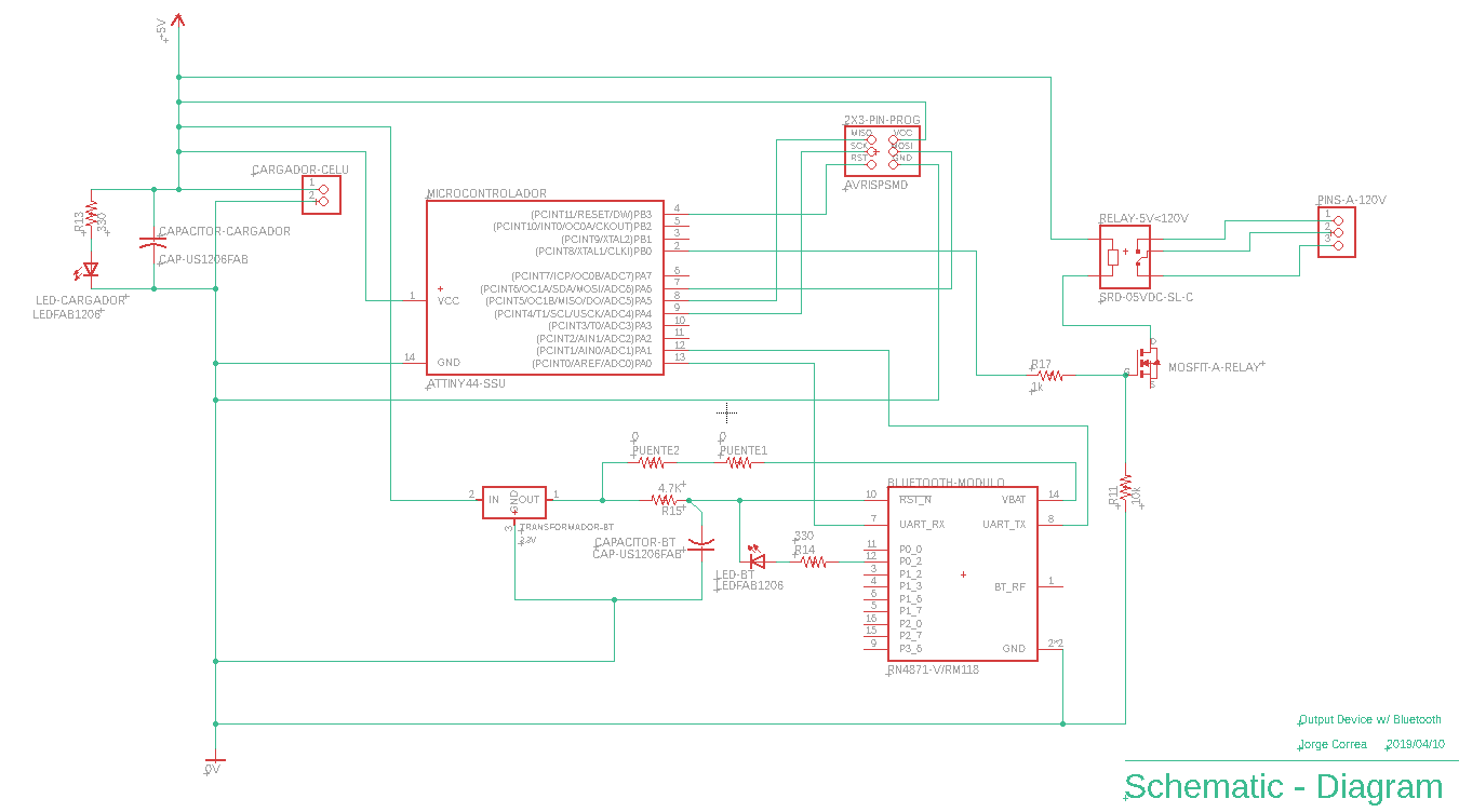
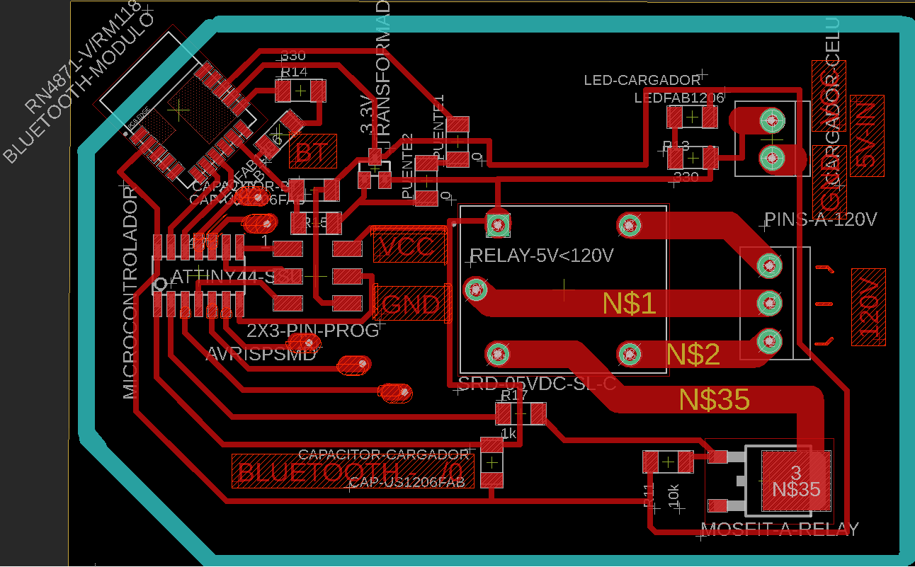
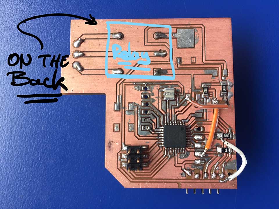
Output PCB: (Week 12)
In this case, the main reason to produce this pcb was again to prove that the relay would turn on and off the coffee maker. Ideally It would have also carried out until the final proejct. Unfortunately It was not possible.
BOM:
| Quantity | Component |
|---|---|
| 1 | Attiny 44 |
| 1 | RN4871 Bluetooth module |
| 2 | LED Light SMD |
| 2 | Capacitior 1 uf |
| 1 | 2x3 pin ISP connector, male |
| 1 | 2x2 pin connector, male |
| 1 | 330 ohm Resistance |
| 1 | 10k ohm Resistance |
| 1 | 0 ohm Resistance |
| 1 | 3.3 v IC |
| 1 | 4.7 k Resistance |
| 1 | Relay 5v - 120v "SRD-05VDC-SL-C" |
| 1 | Mosfit "NMOSFETTO252" |
Debugging:
the bluetooth's vat was not connected, by this point I had already gotten good to create unplanned brdiges, so I used an un-used edge to do so.
After all this debugging, I went back to basics. I created the original, simplest form of rn4871 pcb. To udnerstand what was going wrong from there.
Creating neil's bluetooth pcb
BOM:
| Quantity | Description |
|---|---|
| 1 | RN4871 Bluetooth module |
| 1 | 10 k Ohm Reistance |
| 1 | 1 uf capacitor |
| 1 | IC 3.3 v regulator |
| 1 | FTDI 1 x 6 pins, male |
.JPG)
.JPG)
Debugging, I found the input current from the vIC electornic component outputed 4.7 v. A smiple confussion on my part probably.
My hypothesis is the rn4871 bluetooth might have damaged with higher voltage.
A big take-away is that the module wont return a response on most commands, only ones specifically instructed to do so.
In order to actually program this bluetooth, it was the following initiation steps:
| $$$+ | Enter command mode |
|---|---|
| PZ | Clear all services |
| R,1 | Reset module, take effect all the changes |
I never got passed them but Is what I used to test if I got it working.
Here is some of neils code for the attiny 45 Find it here, its all in py
Back to Basics: Setting up the HC-05
First make sure you have the hc-05 and not the hc-06, as the 06 is not able to become a master and so it required a 05 first. Physically diferenciated with a button on the buttom.

HC-06 = Slave

HC-05= Master & Slave
The Datasheet for the HC-06 is HERE
The Configuration of the HC-05
The button located in this PCB attached to the board is the 'RESETB' pin: that would otherwise requre a low. input in order to reset the module.
This button require >5ms to cause a reset.
Once you have done so, Open the serial port, in this case arudino's port to communicate in the right 'com' port.
This is the code that worked and connected the bluetooth together.
| 38400 | Baud Rate |
|---|---|
| Carriage Return | Set |
| AT | Response= OK // Cheak if you are connected |
| AT+RESET | Response= ok // In order for anything to take place |
| AT+UART=9600, 0,0 | Change the band rate into a certain number |
| AT+UART=9600, 0,0 | Change the band rate into a certain number |
| AT+NAME=S-C BT M | //sets the bt name (Master or slave ) |
| AT+ROLE=0 /* OR */ AT+ROLE=1 | //Slave or Master |
| AT+CMODE=1 | //"enables the search for available devices"-Danny Vallejo |
| AT+PSWD=1122 | //Sets password |
| AT+RESET | // Resets the module and makes the changes active |
At some point it is required to verify what the hc-05 actually has stored in its memory. It was less talked about but usefull in itself. It is basically a inuatinve '?' at the end of the command instead of the actual parameter.
| AT+ROLE? | What role are you {hc-05} on? 0=master 1=slave |
|---|---|
| AT+NAME? | What is your name {hc-05}? |
| AT+PSWD? | What is your password se to? |
| AT+UART? | Response: Baud, Stop bit, Parity. (I didnt fully undestand this but I got them the same on both BT. That seems important |
| AT+CMODE? | Same idea, have the same. 0 = connect fixed address, 1 = connect any address, 2 = slave - loop |
This is in case you are testing out one that is not new, yours or possibly just rutine cheak.
This section is not as talked about on Arduino forum tutorials but is just as important for the next step of playing arround with the HC-05 BT.
Connecting between my 2 pcb's
I used my input pcb and output pcb, connected between bluetooth in order to test for my final prject.
The same scenario: If the input pcb sent a 1 (recives a person), the output pcb turn on the Relay (Instead of the led) finishing the opeation.
The follwwing is how they connected:
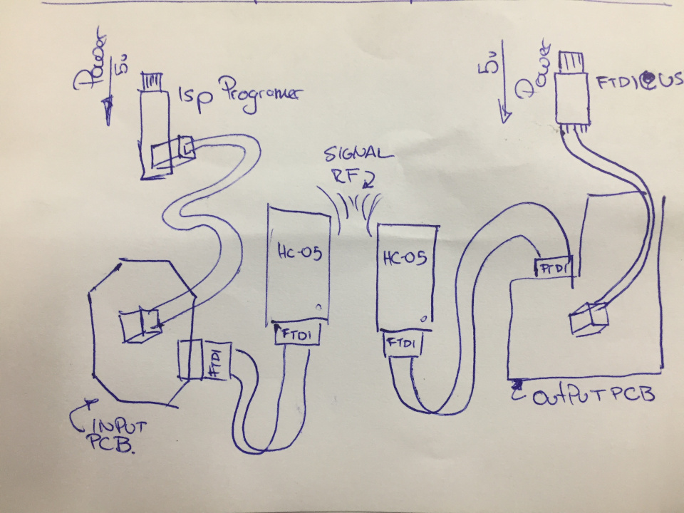
Here is a video of them connecting between each other:
Input pcb's code:
 #include 'SoftwareSerial.h'
    SoftwareSerial ftdi(2, 3); // RX-1(PA3) | TX-1 (PA4)
    char data = 0;

    const int boton = 7; //PB2 pin de boton
   // char transmit = 3; //PA7 TX T44


    int estadoboton = 0;


    void setup()
    {
        // initialize the LED pin as an output:

       // initialize the pushbutton pin as an input:
     pinMode(boton, INPUT);
      //intialize connections seriales

      ftdi.begin(9600);  //Default Baud for comm, it may be different for your Module.
     // ftdi.print("The bluetooth gates are open.\n Connect to HC-05 from any other bluetooth device with 1234 as pairing key!.");

    }

void loop() {
  // read the state of the pushbutton value:
  estadoboton = digitalRead(boton);

  // check if the pushbutton is pressed. If it is, the buttonState is HIGH:
  if (estadoboton == LOW)
  {
   delay(100);
    ftdi.print('1');

    //digitalWrite(ledPin, HIGH);

  }
}
    //Reference: https://exploreembedded.com/wiki/Setting_up_Bluetooth_HC-05_with_Arduino
Output pcb's code:
#include 'SoftwareSerial.h'
    SoftwareSerial ftdi(10, 11); // RX | TX
    char data = 0;
    char relay =  13;//const int
    void setup()
    {
     pinMode(relay, OUTPUT);
   //   Serial.begin(9600);
      ftdi.begin(9600);  //Default Baud for comm, it may be different for your Module.
    //  Serial.println("The bluetooth gates are open.\n Connect to HC-05 from any other bluetooth device with 1234 as pairing key!.");

    }

    void loop()
    {


    if(ftdi.available()>0)
    {
      data = ftdi.read();
      ftdi.print(data);

        if (data == '1')
         digitalWrite(13, HIGH);
        else if (data == '0')
         digitalWrite(13, LOW);
      }

    }

    //Reference: https://exploreembedded.com/wiki/Setting_up_Bluetooth_HC-05_with_Arduino
Once you open the terminal and send a '1' from the input pcb. The Input pcb sends it to the output pcb. The output pcb in turn reads the '1' and turns the relay On
Once you open the terminal and send a '0' from the input pcb. The Input pcb sends it to the output pcb. The output pcb in turn reads the '0' and turns the relay Off
Group Assignment: Send a message between two projects
At this point in time, I had most of my final proejct working. Hence It was a great time to play arround with the aquired knowladge and actually connect two final projects.
I modified slightly the code from my final project to activate Ale's Project:Upcycle Fab Dome
My project is based on a binary output, sending either a "1" or a "0" acroding to wether or not someone is on the chair.
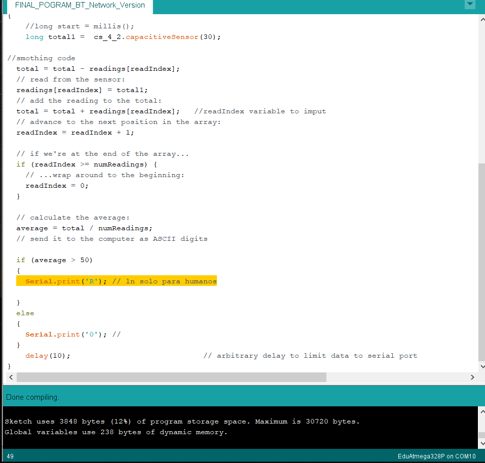
On the other hand, Ale's project is based on a series of letters in acordance to the light required to be emmited from the dome modluar section. As an example: "R" = Red LED's Turning on.
We both used HC-05 Bluetooth module so I basically switched my reciving bluetooth with her's in order to achive communication.
I later switched a couple of characters in order for the char and the dome be connected, as follows:
#include "CapacitiveSensor.h"
/*
 * Paul Badger 2008
 */
CapacitiveSensor   cs_4_2 = CapacitiveSensor(13,11);        // 10M resistor between pins 4 & 2, pin 2 is sensor pin, add a wire and or foil if desired

const int numReadings = 10;

int readings[numReadings];      // the readings from the analog input
int readIndex = 0;              // the index of the current reading
int total = 0;                  // the running total
int average = 0;                // the average

void setup()
{
   cs_4_2.set_CS_AutocaL_Millis(0xFFFFFFFF);     // turn off autocalibrate on channel 1 - just as an example
   Serial.begin(9600);
   for (int thisReading = 0; thisReading < numReadings; thisReading++) {
    readings[thisReading] = 0;
  }
}

void loop()
{
    //long start = millis();
    long total1 =  cs_4_2.capacitiveSensor(30);

//smothing code
  total = total - readings[readIndex];
  // read from the sensor:
  readings[readIndex] = total1;
  // add the reading to the total:
  total = total + readings[readIndex];   //readIndex variable to imput
  // advance to the next position in the array:
  readIndex = readIndex + 1;

  // if we're at the end of the array...
  if (readIndex >= numReadings) {
    // ...wrap around to the beginning:
    readIndex = 0;
  }

  // calculate the average:
  average = total / numReadings;
  // send it to the computer as ASCII digits

  if (average > 50)
  {
    Serial.print('R'); // ln solo para humanos

  }
  else
  {
    Serial.print('O'); //
  }
    delay(10);                             // arbitrary delay to limit data to serial port
}
To Conclude
It was enlightning to actually work through a bluetooht module. At the end, with the proper knowladge: straight forward. I was Impressed. Unfortunately I sitll require and plan on learning another module that can run with low energy as it has wider practicle advantages.
I am howerver well aware as this excersice and and its work has just scratched the surface of wireless communication. Bluetooth requires much simpler now-how that what wifi would, and bluetooth 2.0 is far more basic than the current 5.0 bluetooth.
Being able to prototype with an integrated bluetooth however, on whatever application might pop up is an hot for sure.
As far as the rn4871 I was expecting, and I made it clear for it to be much simpler, yet I cant put my finger on what was not simple yet. I think if I actually look at it now, I would probably figure it out. I would get new modules though.I suspect between all the saldering and fidelling they might not be fully operational, and still not sure how to cheak yet.