Computer-Controlled Machining
Assignment List
- Group assignment ☐
- Test Runout ☐
- Alignment ☐
- Speeds ☐
- Feeds ☐
- Toolpaths for your machine ☐
- Individual project ☐
- Make something big on a CNC machine. ☐
- Explain how you made your files ☐
- Show how you made somethign big (setting up the machine, using fixtures, test joints, adjusting feeds, depth of cut ☐
- Described problems and how you fixed them ☐
- Included your design files and ‘hero shot’ photos of final object ☐
- To Conclude & Reflect
Group assignment
In our case we will be using the machine CNC Roter 1325. A test file borrowed from Alex and Guillermo Before that. Keeping with the local fab's tradition. An exagonal shaped cut part containing variable cutting methods for assembly.
Imported the file into Artcam.
.jpg)
create new model
.jpg)
Vectors >Import > select .dxf (2004 version)
.jpg)
profiling the path.
.jpg)
2d area clerance (just to score)
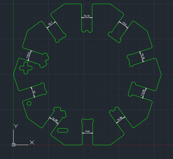
. = 15 mm , + = over 15, - = under 15.
Everything in .05 mm increments
.jpg)
G-code simulation here
artcam passes 5 times to cut (3mm plunge motion, and 2.5mm plunge to score motion)
.jpg)
Us loading the code to cnc linux
.JPG)
The actual tool to cut with (this case a straight doubel fulte flat head 4mm milling bit)
.JPG)
setting the Z-axis homeing
by touching the brass sensor and offseting 15mm down
.JPG)
In this case I modified the original file made by Gillermo and gave it much more smaller and partern even steps. Unfortunately we later realized the material was closer to 15.2 than 15mm (as the provided intended) So the material had a snug fit at 15.25 mm(the widest). I'll be using a joint clearance of 15.35 just so it sort of slides.. hopefully.
Find the Original File here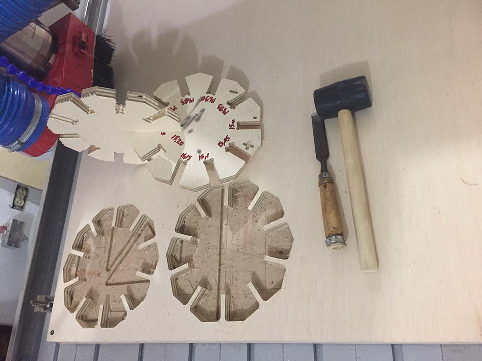
Group Assignment - Safety first

Picture from instructables
- no sandals. Use correct footware protection!
- protect your hair (by holding it and not letting it fly) At the same time, dont ware hoodies or any other strings hanged. Dont have long sleves hanging.
- protect your eyes with glasses and ears with ear covers.
- always be with another person when machining as to not forget any step and to watch over each other and have a proper machining process
Individual Assignment
Reasearch
There is soo much to do, and I'm especially intrested in this section's capabilities to create and control insane joints that otherwise would never be cost/tiem effective. With that said, *as my instructor pointed it out to me* Ill be sharing this article about 50 Digital joints (download printable poster yay!), also breafly mentioned in class. Aparently flexiblestream is atributed to be owner by archidaily but the source webpage is broken.
- In the following is a list of interesting resources I found stubeling about.
- A papaer evaluating the use of cnc for small and large scale production in furnite, talking as a case study germany
- A presentation comparing the traditional and digital jointery
- A carpentry joining traditional craft with digital production. (in this case 3D printing and not millng, intresting non the less)
- A overview of the small to extramly large wood-basd computer prodcution from the recent past. Covering everything from advanced furniture tecnologies as is double sided kerfin, not possible without computer machining to self suporting structures for public spaces like the Metroplo Parsol.
Individual Assignment - Furniture Development
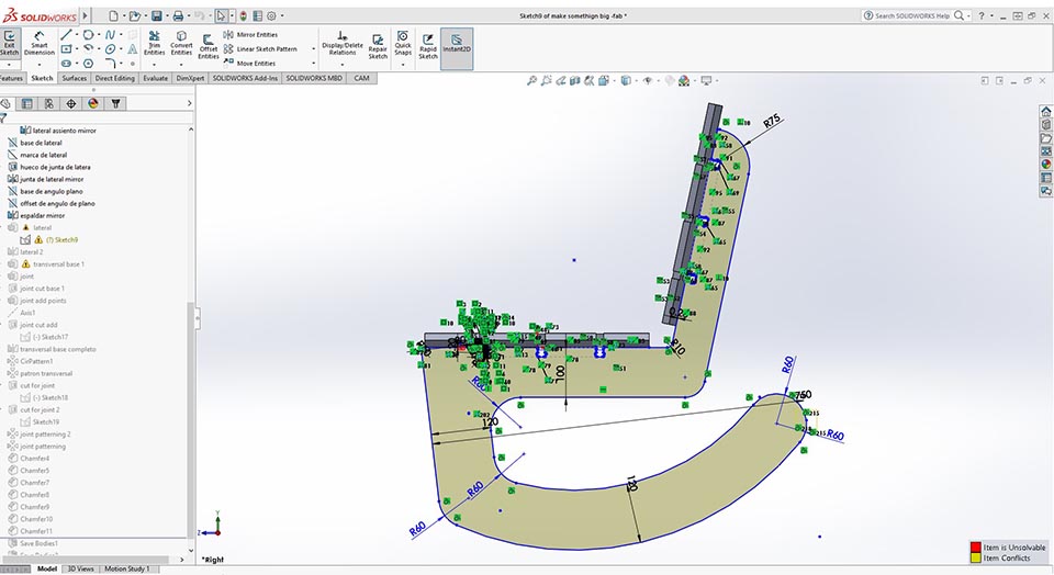
In this section I decided to use the previous chair iteration done on On-shape in Computer aidded design week. And redraw it using snapfits (taken from earlier reaserch).
Creating in this case a rocking chair simply for the fun of it. I would be proving the building method, and a place to rest. Who doesn't love a roking chair?
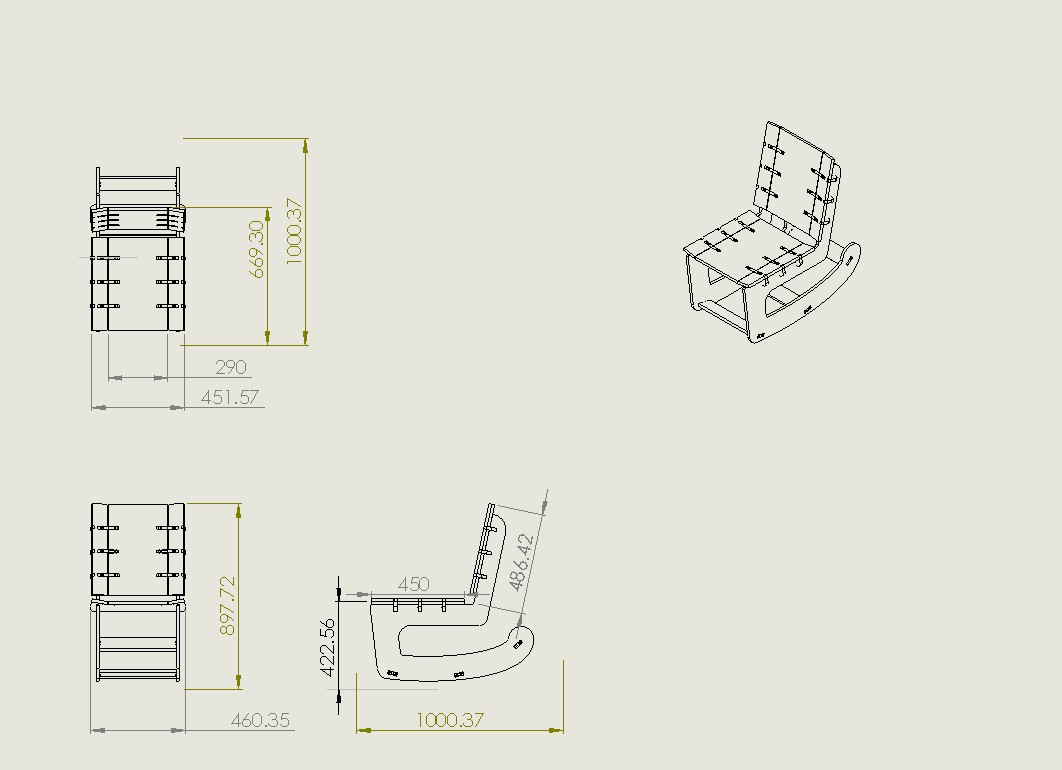
We see the final chair. Reduced from the initial dimentions to fit in 1/2 sheet of playwood.
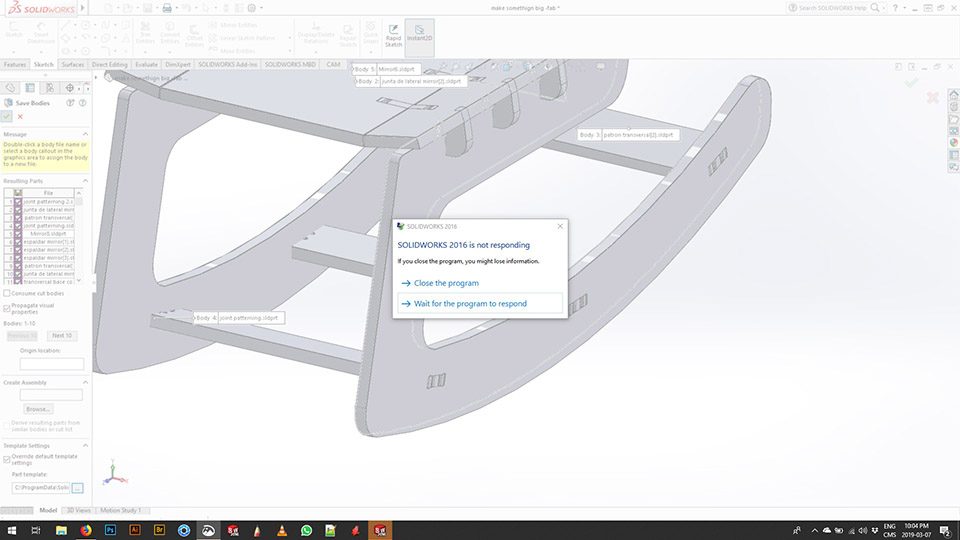
Solidworks gave me a hard time exporting all multi-body part as an assembly. It also was not usefull as the assembly did not have any mates shown. I instead saved them as a single parts and rebult it ina an assembly file. Find it here. I normaly would work as multibody parts and just make an excel spread-sheet for cutting later on. Never cutting as complex shapes as it is required in this instance.
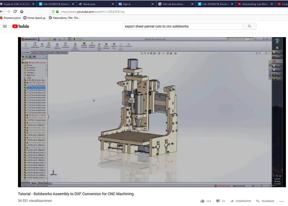
I found a helpful video to create the cut in solidworks. In order to later send this to cut. Local production would typically require complex shapes to be printed and re-drawn by the carpenters. Time consuming and never exactly the part required. Find the video here.
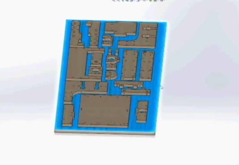
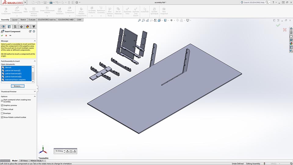
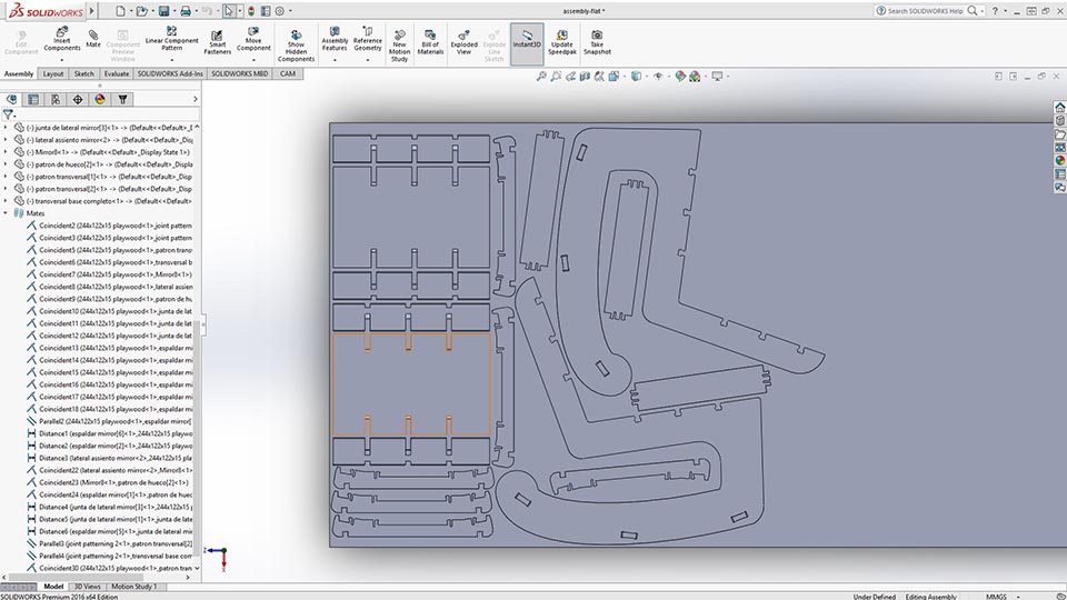
Here is the final result of the tutorial. Every part is mounted on top of the actual board size.
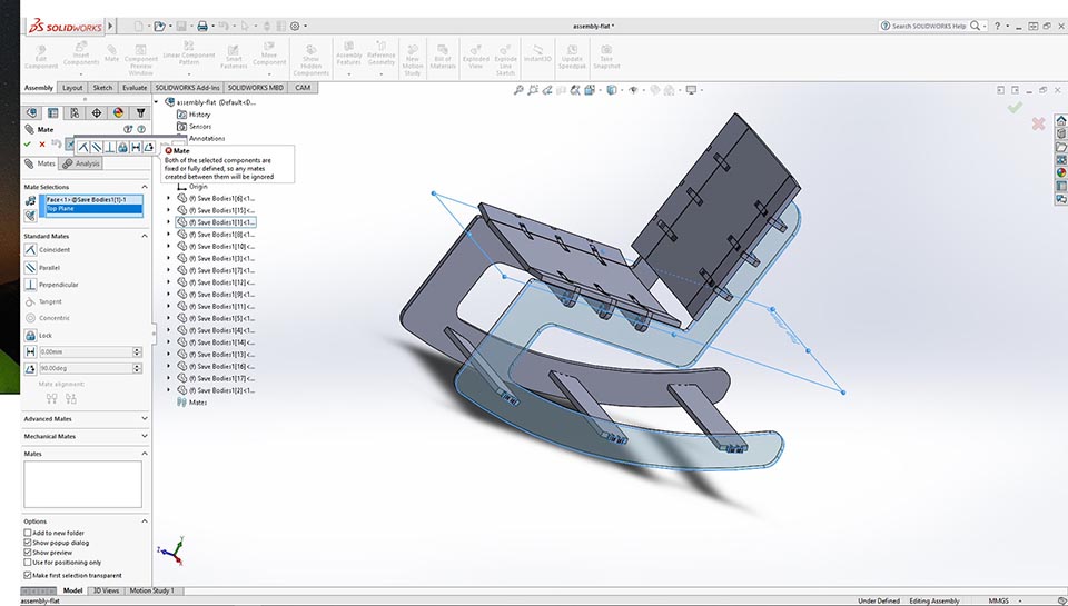
Here is me mating the assembly again, mainly to mantain that all joints are aprox what they should be and that everything is in order.
Here we see the final sheet of ply and most of the pieces in the assembly. Ready to assemble for cutting portion of the setup.
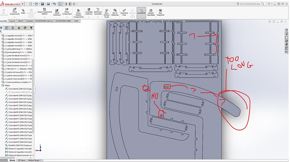
After the 1st setup of the material on top of the sheet, It was my thinking that too much material became wasted for a longer rocking motion. Aside the joint females from the lateral chair parts became assembled upside down (not showing the relif for the sanp fit to rest on). Aside the panels from the back rest and bottom did not have all the snapfit releif either.
In the assembly some referances in the drawing where not showing, something broke and the relif extrude cut was just not there. I ended just deleting the references, and hope I dont have to move the drawing again. lol. The best ways to avoid this problems is though proper organization, using ecuations (I use on important things as material thickness) and references based solemly from the main planes. I just didnt due to time constrains.
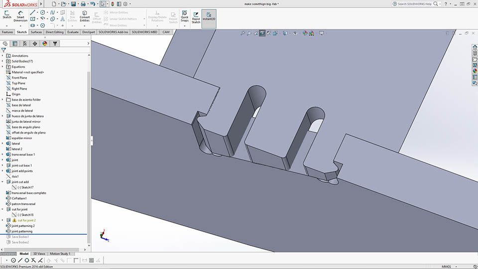
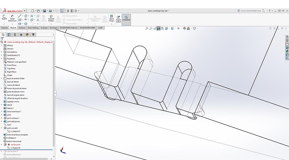
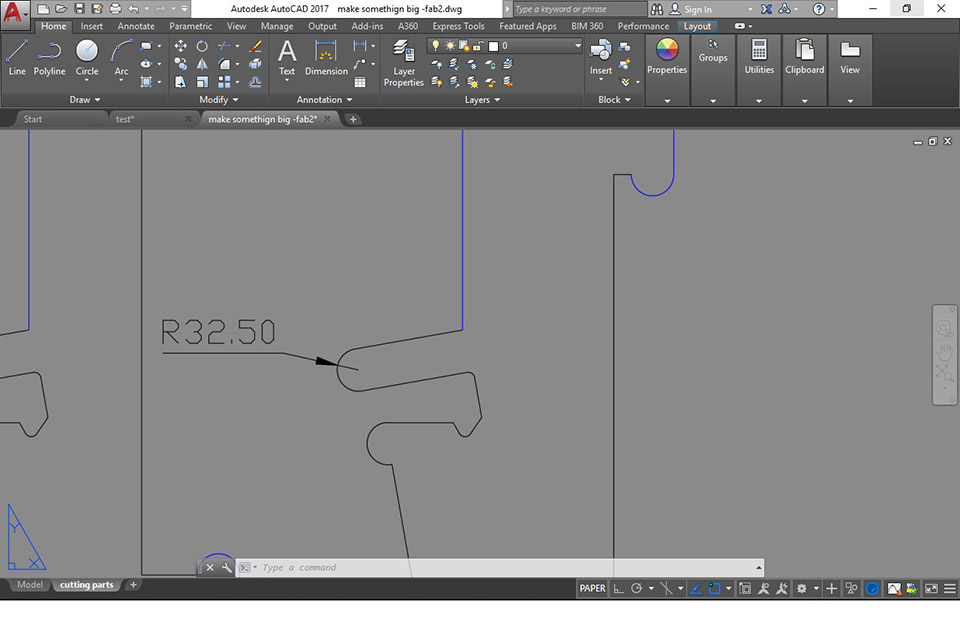
We find the snap-fit relif fixed and a 4.5 Dia mm spaceing for the 4mm Dia bit.
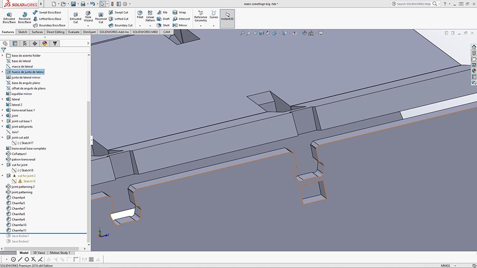
In this case, I was going to implement a second snap fit in order for the joint to become harder to open. Then i realized that that will just brake as that bridge would be the first support of person's full weight and weight multiple force when stoping the person as it sits down. Surely to brake. I decided to instead to decrease a 1mm extra so that the fill will be a pain to insert but never will it brake loose. This joint was initially insipred by the chilean pavilion construction method, part of it we still keep in the fab.
close-up on the snaping mechanism. (chilean pavelion project of 2013)
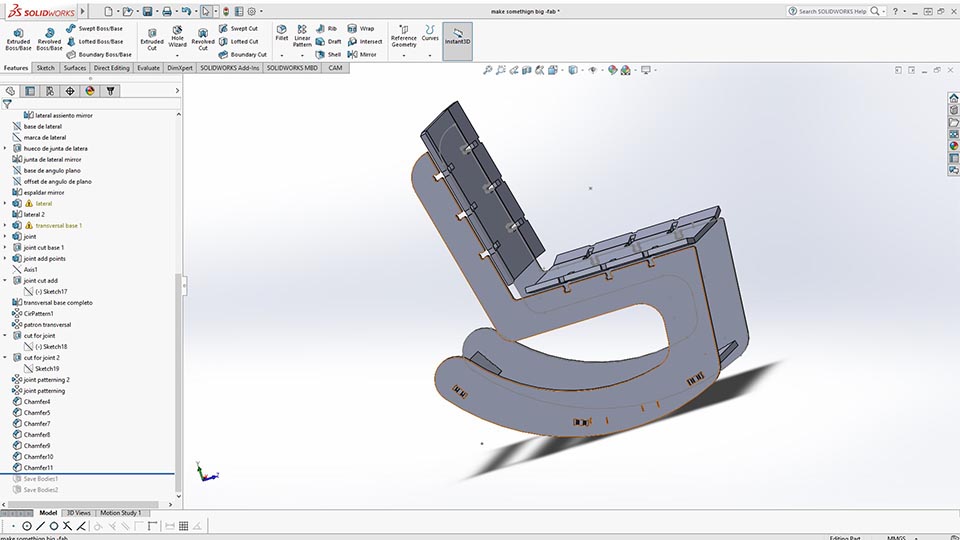
Here we see the rocking chair with the rocking base shortened from 1000mm to about 760mm. Resulting in a higher efficiency cut.
That is 1/2 a sheet of play my friend! Think about this, a 15 or 18mm thickness play sheet with our finest hardwood veneer finish (Seyke wood, depending on who you ask) outside will be $90-150. That means the chair you are looking at is $45-75 in prime material. Add a $20 days of labour, $5 in linseed oil and you get a finished product. Multiply the production cost by 3 (rule of thumb for adicional labour and utility markup and you are still talking about $210-300. YOU ARE NOW AT A PRICE COMEETITIVE IN AMAZON. The shoking thing is that you are doing a custom part, not a scale production.
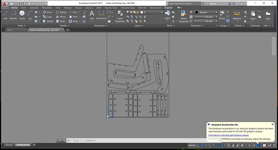
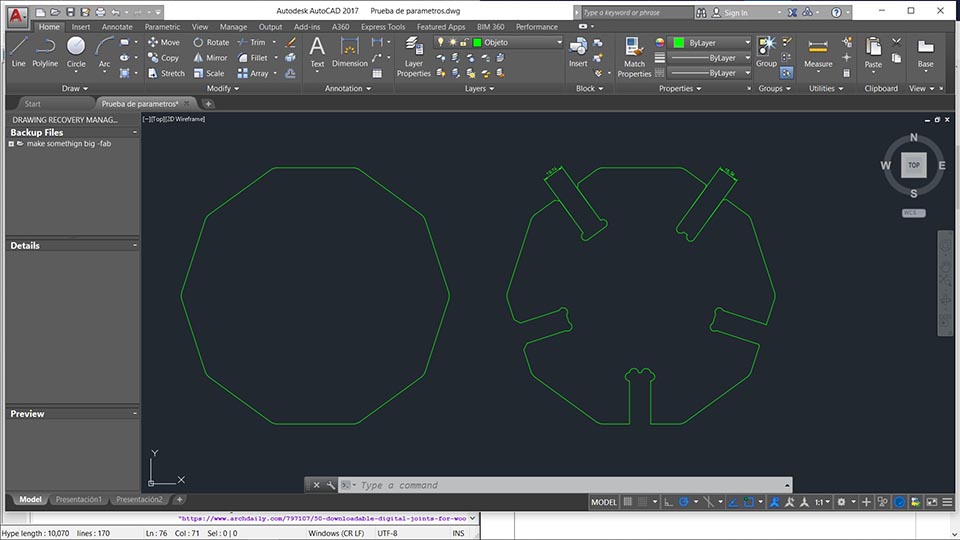
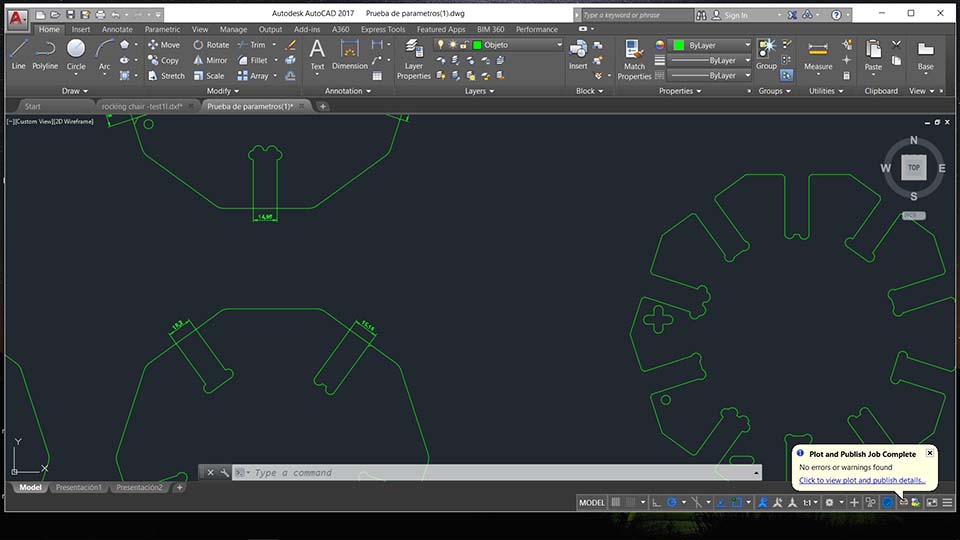
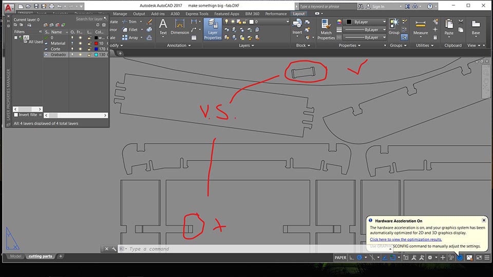
I used autocad to read the exported .dxf file, later edited a couple details. Separating the releif cuts (5mm plung action) and the full material cut paths (15mm plunge cut). Have a look at how I did that here The catch is that you require to do it from a drawing, you cant do it directly from a part or assembly.
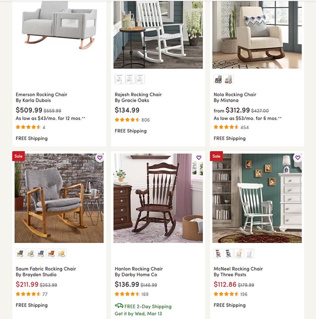
The amazon fast search for market price rocking chairs.
In the end im exporing to experiment what might be faster to create the releif tool path. If though the 3D geometry in solidworks or though the post process in autodesk. To be confirmed. The advantage in solidworks might be that you could and should make a releif based on a global variable so as to change this when the bit changes. But that means other parts of the geometry as the snapfits might also have to be added with global setting. Good practices but time consuming and not always worth it. Ill keep in mind though.
Solidworks! Solidworks is faster. Always with proper planning.
Especially making this complex jointery, in mass production you would create smart components and have parameters on the releifs for the bits to adapt to the tooling.
In my case, i was all done by hand on autocad. I later found compatiblity issues I was never expecting and eat all my designated machining time. It became close to 2 working days.
.jpg)
This is me trying to machine arround the part in artcam after importing the file from autodesk with corrections.
.jpg)
This is me finding out that multiple contours where opened after I purpusefully closed them in autodesk. For this inspection: Assistant > vector tools > vector doctor (green cross) {select all paths} > Idenify.
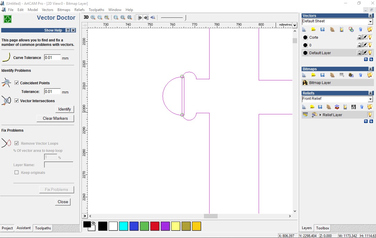
This section art cad showed me an error circle. In reality it was pointig out that the paths intersected. not a problem It just had me searching futlessly what the problem might be.
.jpg)
I found a couple of not proper trims that didnt show up in autocad but did show up in illustrator.
.jpg)
Alex (instructor) told me of a siilar problem he had before. And how he had fixed it by importing the dxf file into illustrator, later saved as version: illustrator 3 . And opened it flawlessly. In my case just multiplied the problem.
Technique that sort of worked arround the already closed profile that didnt actually work.
.jpg)
Alex (instructor) told me later= using Illustrator to figure out open contours. 1. cntl + A (selecting all paths) cntl + j (joining all paths) All paths that sort of went crazy where the opend ones. I paciently folowed them and In Autocad extended every path (both crossing lines) and proceeded to trim them again.
.jpg)
Ale (class mate) later indicated a "overkill" autocad command. I started using it with tollerance 0.000001 (default) but ended using 50 in order for it to work. It would typically erase 1 line and later i re-drew it. Join the full path and hoped it was closed.
.jpg)
I later just hypothise the real problem is that artcad has an issue with using cicle translating into straight lines. I hence proceeded to create fillets and splines instead of cicles with trims. The software later lett me export my g code. A day and more, late.
Proving my concept chair built
In this case because we where about to cut a 15mm ply, I found it best to be sure what I was cutting would be correct. Last thing I want are wood cuts that cannot assemble and are only good for fire wood.
.JPG)
The first try i got my scale wrong (in accrodance to the mdf 3mm material.) So the joints where frutelless.
.JPG)
It did show me problems that could be fixed.
.JPG)
Later to cut in proper scale, the file was as corrupt as our politics. I sent it to illustratos, saved it as ilustrator 3 and sent it to the lasercutting machine to find it working flawlessly.
In the end this was my prototype. Brought me lots of joy. It still has some balancing issues I will have shake off on the account that this week is done.
The Machine Cutting
The actual machining was done in a 15mm Ply with a 2 flute, flat head, 6mm bit.
Setting up the playwood, I didnt think of placing bridges and so I decided to curreclty align screws to hold the finished cut parts in place. It looked like so:
.JPG)
Using the raw data and pin pointing the place where a screw would not touch the bit.
I had a problem in the time of cutting, when the bit did touch a screw that was placed before the cnc's g code, in order to fix the ply wood in place.
.JPG)
I noticed that the cut was still not cutting all the way though the material. So when the machining stoped, I used the time to re-zero the z axis about 2 mm deeper.
.JPG)
When the final machining was done, there still was 1 hole in the side joint of the chair that I missed when loading the code in. As youll see in the next image.
.JPG)
The answer was simple, but not necesarily Intuative. Using the same homming in the x,y and z axis loaded only the missing g-code to cut the missing hole. And It worked fine.
.JPG)
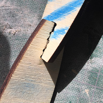
The final machining was done. It came out like properly. It did however became hard to fit, as the snapfits where too tight and was required to cut the teeth.
.JPG)
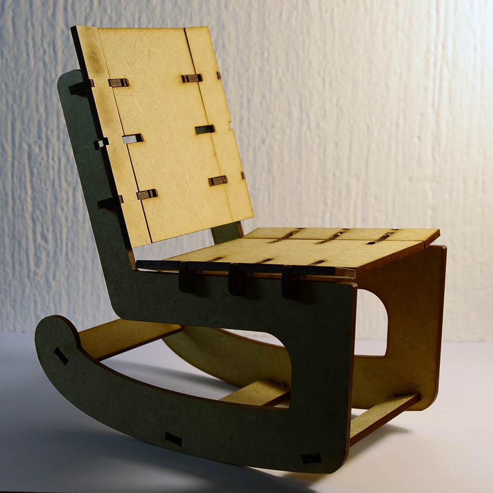
The final product
.JPG)
.JPG)
.JPG)

To Conclude
Honestly after everything I would have liked to plan a little bit better how to create all the joints, more than just a thimbnail sketch. It would have taken less of my time in the long run.
The other thing is I would have loved to learn cam hsb plug-in for solidworks rather than artcam. As the amount of time spent into the simple process would have un-doubly been enough for that learning experiance. Instead of dealing with senceless software incompatiblity issues.
I still am not done with my cnc milling as the last night was upon us before my gcode working.