Computer-Controlled Cutting
Assignment List
- Group Assignment ☑
- Characterize your laser cutter's focus, power, speed, rate, kerf, and joint clearance. ☐
- Individual Assignments ☑
- Cut something on the vinyl cutter ☑
- Design, laser cut, and document a parametric press-fit construction kit, which can be assembled in multiple ways. Account for the laser cutter kerf. ☑
- For extra credit include elements that aren't flat. ☑
Group assignment
- Characterize your laser cutter, making laser cutter test part(s), making test part(s) that vary cutting settings and dimensions.
- BCL1610x
- The laser's focuse distance is 8mm from the material ment to be cutting.
- Working area: 1300x900mm
- Laser Power: 120 W
- Laser Type: CO2 sealed laser tube, 10.6um
- Cooling type: Water Cooling
- Always be aware the temperature does not rise, and if it does you require to let the machine cool down before performing more cutting.
- Engraving Speed: 0-6000mm/min
- Cutting Speed: 0-40000mm/min
- Location Accuracy: ≤+0.01mm
- Further on we will analize a series of cuts to determine the actual acuracy of cut in retrospect against the manufacturer specificaitons.
Laser Specifications
Clerance Test
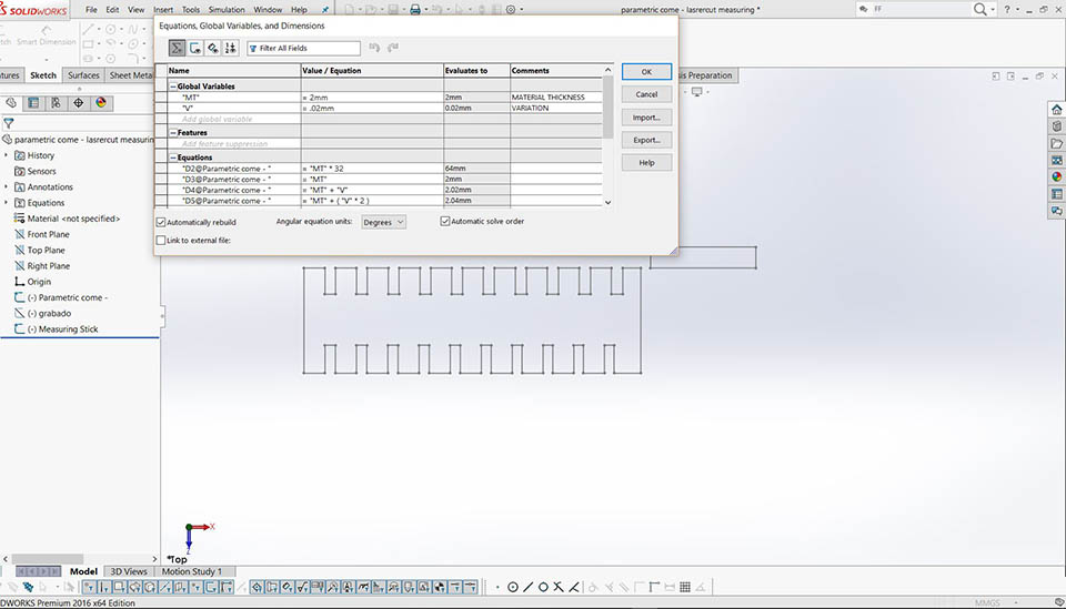
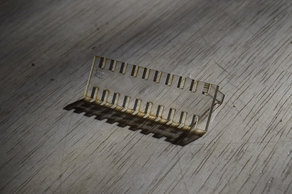
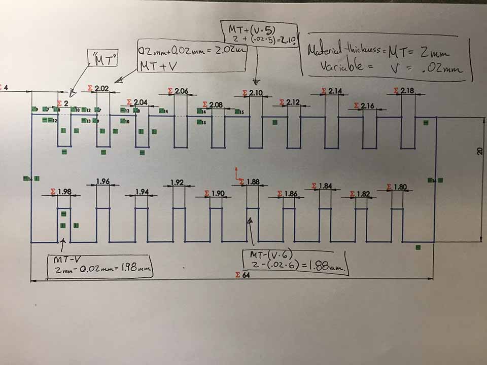
On the group assignment we developed a parametric come, that jumps every .02 mm in thickness, starting from 2mm (acrylic thickness) +/- 10 steps.
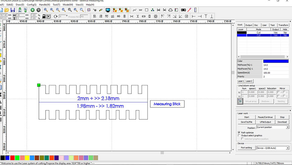
Next to the come, there is also an elongated rectangle. It's ment to be a stick to try out what slot is the material's exact match.
.JPG)
The end result was the sick matching the 2.18mm to the thickness of the material (2mm)
A range of 1.8mm to 2.18 mm With a top right slot that in theory would be 2mm exactly.
In the group assignment, I was assigned the come its self. Drew it on Solid works and created a parametric 2D drawing. Variables states were: thickness of material, and the variable change. Later used equations referencing both variables, hence, ="t"+(v*2)=2.04mm.
here is a small fail, that happened testing the parametric feature the drawing took me to make. Apparently some gaps existed i was not aware of.
always make sure everything is properly closed, and have a better grasp on relationships. The SolidWorks has a gap tool that found to be incredibly useful. Toolbar/sketch/repair sketch Deeper Detail
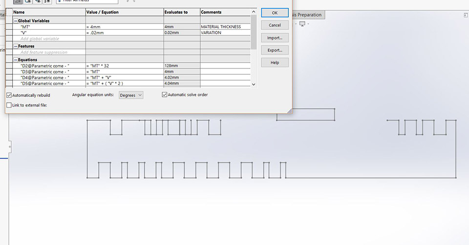
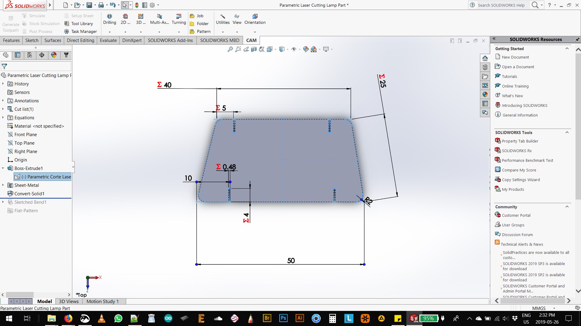
The final parametric design, is explaned in the following pictures in detail. It has 2 variables: 1. MT (material thickness) and 2. V (variable). Its idea is to only enter this 2 parameters and the rest of the dirawing will atumatically proportion is self acordingly.
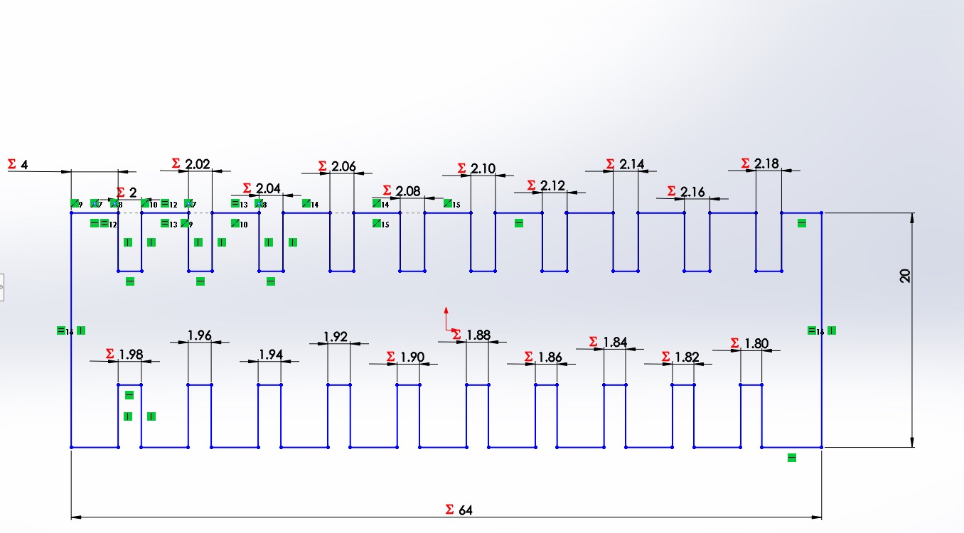
Drawn is an explanation of the equations used in each side. Where one is less than the material thickness (MT) and the other is more than MT.
Parametric modeling:
Regarding parametric modeling, in sowlidworks I initially leared in applied to cabinetry. Find it Here
It is however a tricky bussiness, as its not the most efficient process and making everything parametric is not always the best route: It takes much longer.
Regardless, when something like the width of a material will change, as it would to in the come for it to apply this test to multiple material thicknesses it makes sence. If you already have finished dimensions or are reverse engeneering something it might not make sence.
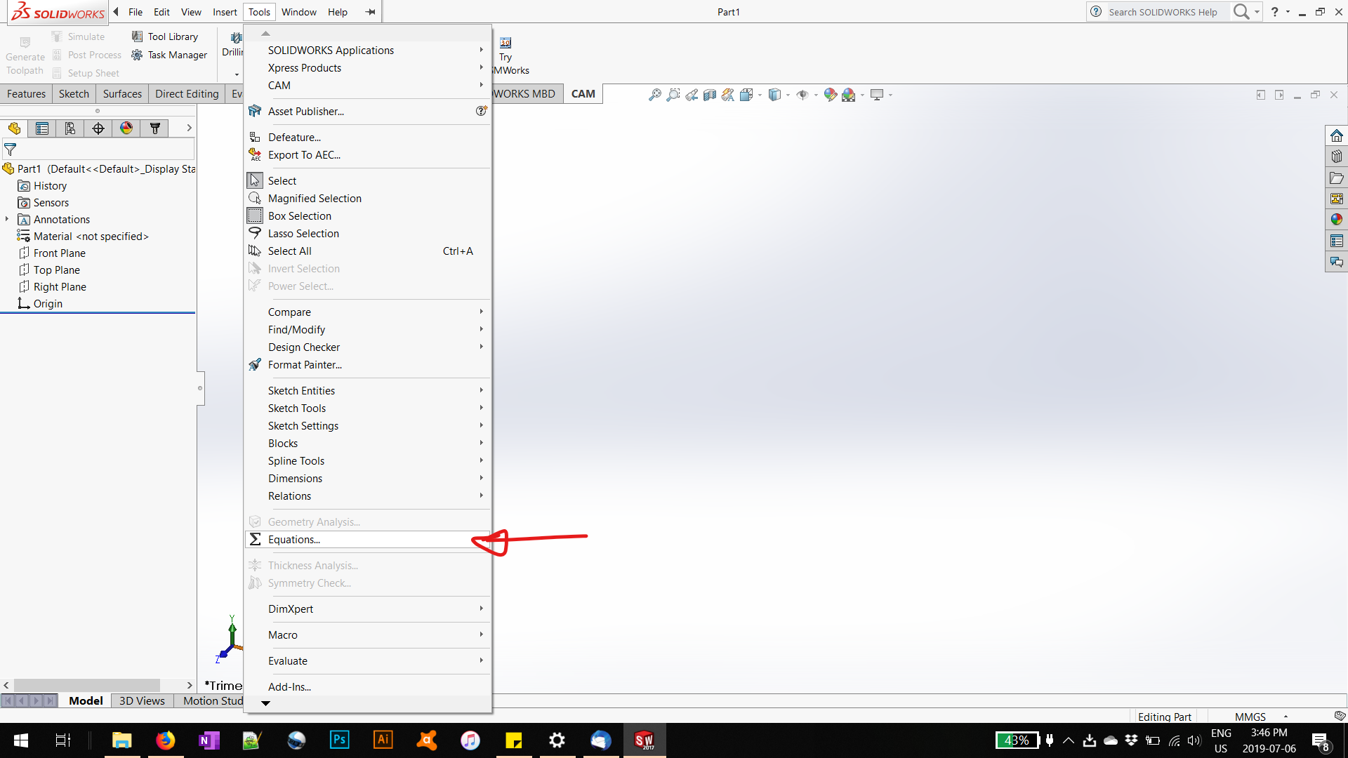
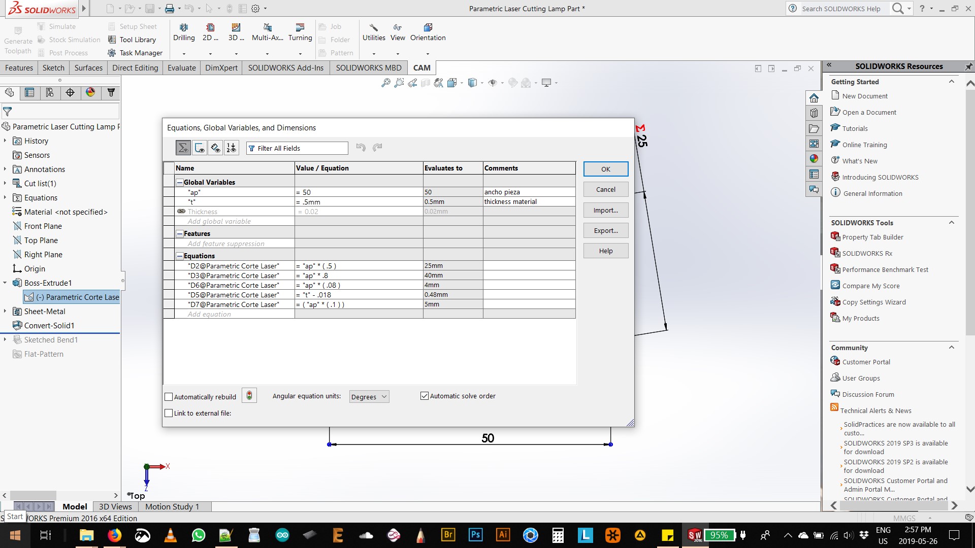
1. Under the toolbar: Tools>Equations Here you open a menu to add the NAME, Value or Equation to later reference or change in the drawing.
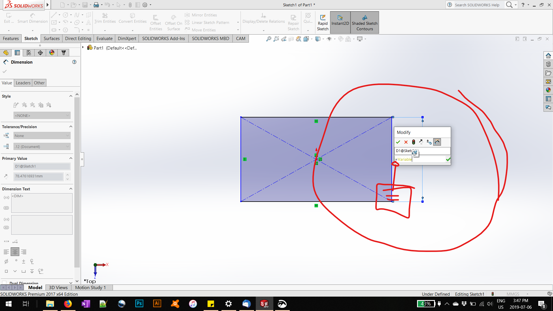
2. One you are entering the dimension with the dimension tool in a sketch or extrude operation, you reference the Value placed above by entering: "=" at the beguining. You later can place the name of a specific variable or even directly creaet one by clocking the only pop-up menu that will show.
Square Cut Test
The lasercut test is ment to determine the thickness of the material. It is another way to do so. It actually was the first test we did as a group. I took less participation in the drawing portion. As It was required to create a parametric come, it my time was better spent in developing that blueprint.
In this case, we did multiple tests to see the required speed and laser power required to cut acrylic.
This test was fully executed by my classmate Ale. We discussed certail concepts as a group, and at the execution time it seemed a better collaboration if everyione tackled a part of the tests and later shared the results.
.JPG)
In this case, the top row was a variation of power, while the bottom row was a variation on speed.
Power Variation ranged from 40 to 80 with a constant speed of 60. The far right is a grotesque burnt result while the far left did not fully separate from the mother material.
Speed Variation ranged from 10 to 50 while a constant power of 30 was kept. The far right was not fully cut, while the far left barely separated and the material melted all around the edges.
.JPG)
The final Results was a variation of .1mm from the 5 mm Sq. expect to cut.
The actual Cut distance was of 4.8mm.
Resulting in a laser thickness of .2mm / line= The joint clerance
I'm Already incredibly grateful for teaching us the concept of a thickness of the laser cut. In the past it I have had multiple problems with slight variations in snap fits and cuts dimensions depending on laser cut machanists. It was always a bit uncertain and hard to communicate the uncertainty because I believe its not well understood in most places.
Individual assignments
- Cut something on the vinyl cutter
Here was our first test, and the results with the blade so deep it went though the material and scored the bottom aligning mat as well. As a result we started with a very slim pressure and went onwards, as not to damage anything else.
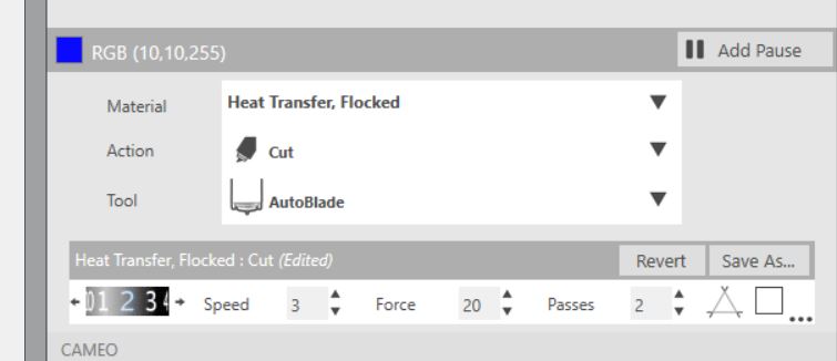
Here are the settings we found to be useful when cutting and engraving reflective vinyl for clothes. It's good information to have handy.
The following is me after I finally got to work on my vynil cut stamp. "JHC" One I ended stamping on a black hoodie and use often.
.JPG)
The vinyl cut, I later realized there was a trasparent paper I was not supose to peal off. So I did cut this again for later placement on my hoodie.
.JPG)
Here is the vinyl after ironing it on the black hoodie.
.JPG)
Here am I happily sporting the vinyl on my hoodie.
- Design, laser cut, and document a parametric press-fit construction kit, which can be assembled in multiple ways. Account for the laser cutter kerf.
Press-fit Kit - Light bulb screen
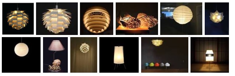
Press-fit kit concept was developed because I needed something to cover a couple of naked light bulbs in an extra room. The concept was to create something that provides a diffused light, that neatly wraps around a light bulb.
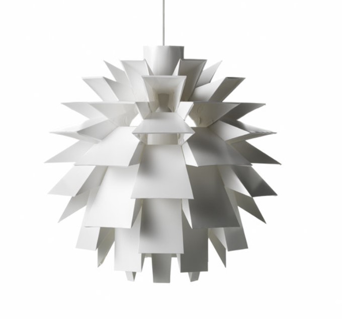
Influences:
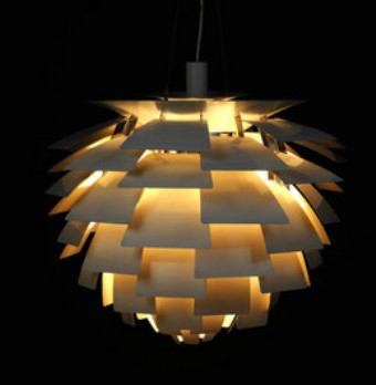
- Norm 69 Lamp by Simon Karkov = A pendant lamp out of polypropylene
- Pintrest has also a bunch of other intresting deviations of the sort.
- Lightopia 28.09.2013 – 09.03.2014 by Vitra Design Museum. I knew of Vitra from before hand yet I have stummbled upon this exhibition online.
- Amazon also sells something similar Under the: Lightingsky DIY IQ Jigsaw puzzle as well a pinstrests shares all the other. I mean if everyone is doing it, i thought I would too.
- There is also Isamu Noguchi's fun projects: Akari Light Sclupltures, 1951
- I also came across a website that calculates the segments and angles required to create complex joints in woodworking: Blocklayer - woodturning segments I used that initially to calculate how many parts I would have needed to create a full lamp circle. I later opted not to attempt and have perfect angles, due to the amount of work required to get them in flat sheets of paper.
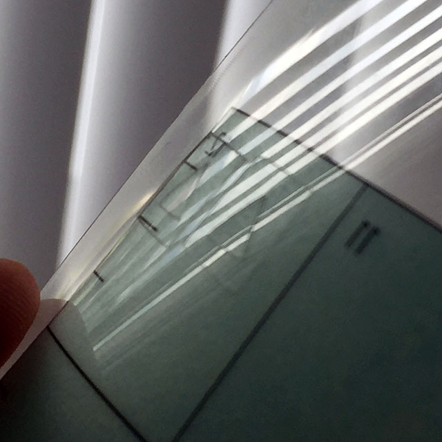
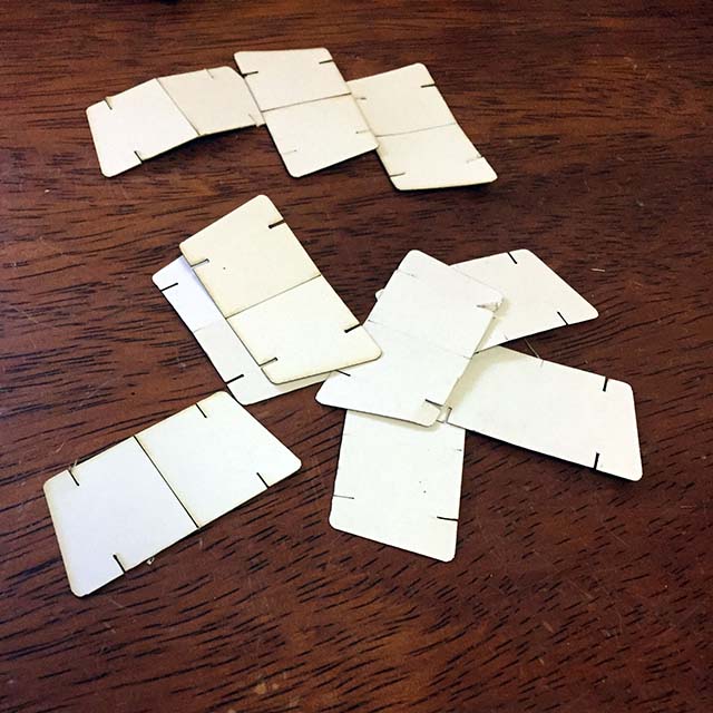
The material for this assignment I decide to use a 20 caliber white packaging paper. I had a supplier on hand due to another project I was working on. It turn out that the thickness of the paper was similar to the actual cut of the laser.
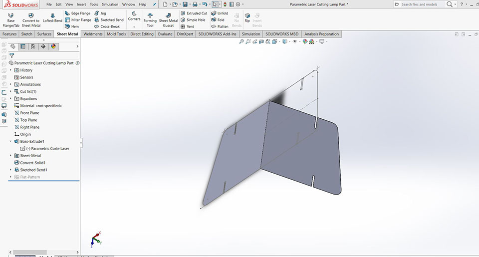
There where parametric in the following way:
The development was a mixture of influcences above and a range of thought:
A simple thought exersice: If a building block is rectangular, by adding one on top of each other, the final wall will be rectangular. If the building block is trapazoidal, then the final wall should correspond to a trapazoidal shape.
How do you give it a 3D without actually having to calculate perpendicular shapes: You fold the parts i half, and let the material deal with the required angle, while still attaching each trapazoid in a parallel fashion.
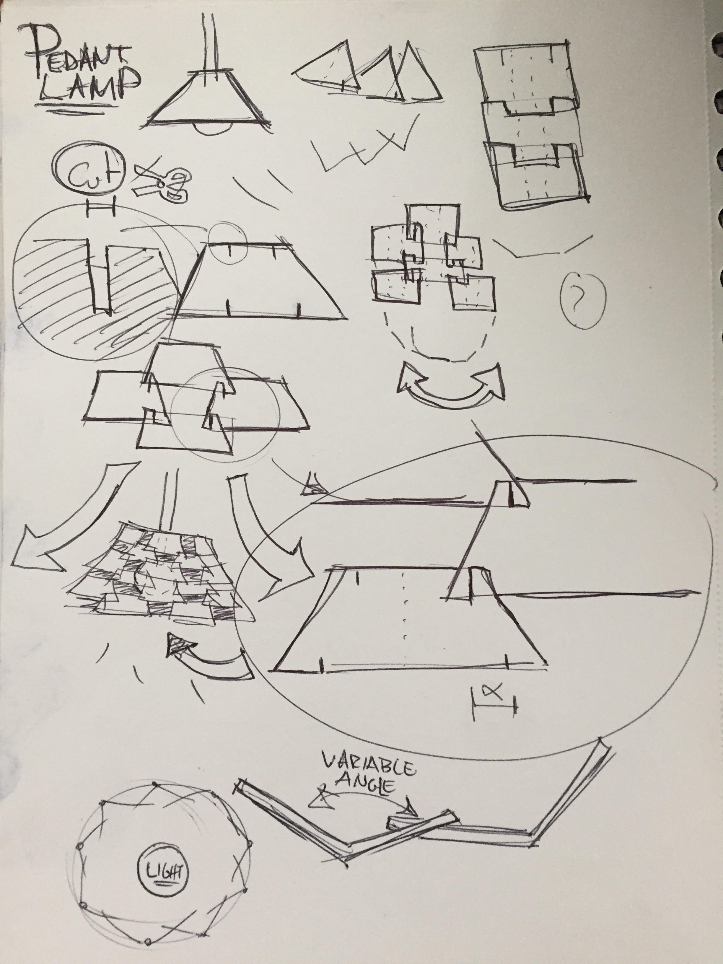
The idea was to create this interlocking system of simple shapes that would morph into a larger organic shape that created into a screen around the light bulb and created a much nicer light.
The cutting process
The actual process of cutting is varied, as it can be from usb cable, wi-fi, or the actual machine. I use USB
Preparing the file in "thunder laser" or RD Works v8 Dowload
| You open the software and Import your dxf or other vector data |
|---|
| Refromat, make sure the starting point is properly oriented. Save it to a connected usbdrive by pressing under tab: Laser work --> Save to File |
| Connect this usbdrive to the "usb memory flash port", in the lasercutter. |
| Read the usbdrive, and copy the file into the lasercutter drive. |
| When you are ready send it to file print. And stick arround, laser burning in this context is never fun. |
.jpg)
.jpg)
The parameters used to cut the 14-18 caliber paper ar as follow:
| Speed: | 300 m/s | Power: | 16.0 |
|---|
In this case 20 pices of cardboard took 2.1 min
Here is the a video cutting the paper:
.jpg)
.jpg)
I later did a 2nd version of the lamp, had a A4 paper close, and just sort of rolled it up creating a lamp. You know, just for kicks.
.jpg)
.jpg)
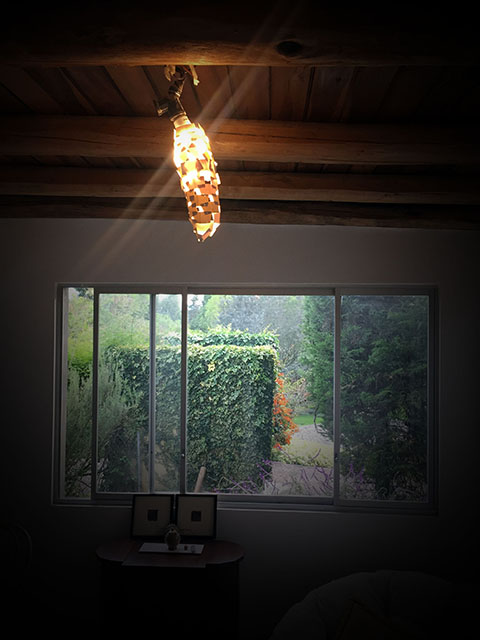
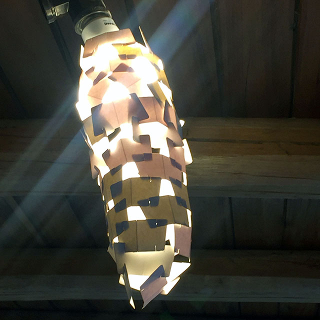
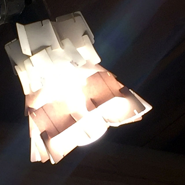
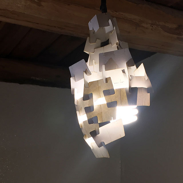
Here is the original final results from that week.
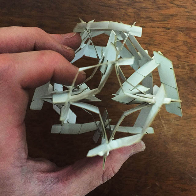
The shapes where intended snap between shapes creating the banana shaped lamp. It was hoverer filled with holes that let the light pass through and the circumference shape did not diminish as expected. It then made me re-evaluate the shapes capabilities and resulted into a experimentation resulting in the later lamp shapes.
The snapping did not work exactly as I planned, but it was enough to create a finning around the light bulb. It was tight enough to hold its own weight and depending on the patten it also created an aesthetically pleasing shape in the day time.
To Conclude
Vynil Cutting
- The prodution and use of vynil cutting was mind opening.
- The especific excersise to create a t-shirt stamp was an activity that toped my expectations. I where the hoodie every day.
- But so far beyond the contect of creating a werable, the vynil has far more aplications as is cuttng cardstock and copper. Impresive extentions a simple knive can have used correctly.
- Another surprise was the ease with how the machine, and its software became. We as a collective group where working away with this machine in about hour tops. Most times that is the amount of tine another machine requires to setup and understand its components.
Laser Cutting
- Lasercutting was an eye opening experiance, as it is a tool commonly used to create prototypes and final products alike. To understand that it cuts with tickness is a majestic realization and creates the ability to use the machine's acuracy to its fullest.
- The machine's aacuracy makes it the most acurate machine I'll evern work with on need to use. Its hard even picturing a 0.018 mm cut.
- As far as the press-fit kit goes, it did create the expected outcome. A light shade or cover. It was not the way I was expecting it to react, as it was done in a fly. I It was intresting to use this cardboard material as ist's thickness was 18 caliber: about the thickness the laser cut's thickness is. It was a sturdy material that also had an nice translucency creating it a good fit for the kit.
- The lamp shade might be a good fit as far as process goes (leaves a almost no trace of cut). The total area was about 6 A4 papers in aproximately 10 minutes. The cost paper was less than $1, and the cost of cutting time is about $3-5. Creating a $6 lamp shade could be a viable alternative, alternatively an lampshade could be sold $15-18, or more.