3D scanning and Priting
Assignment List
- Group Assignment ☐
- Test the Design Rules for your Printer ☐
- Individual Assignment ☐
- Design and 3D print an object that could not be made substractively ☐
- 3D scan an object (and print it) ☐
- To Conclude & Reflect
Finding the Limitations of a the 3D Printer
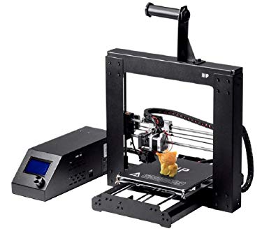
Monoprice Make Select Plus 3D Printer
- Print volume: 200 x 200 x 180 mm
- Max. print temperature: 260 degrees Celsius
- Heated bed: Yes
- Layer resolution: 0.1mm
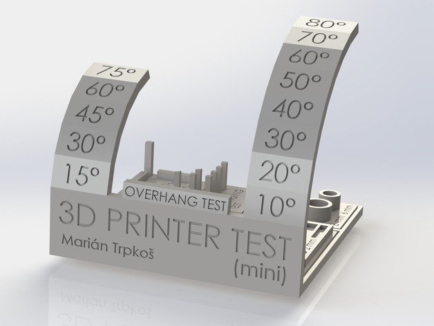
The Print test
.JPG)
.JPG)
.JPG)
.JPG)
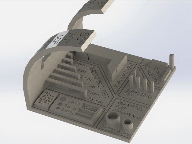
In this case we did as a group print the earlier file. We see this test as a very labour intensive test for the 3d Printer
- Scale Test: +- 0.5 mm
- Stringing Test: The performance was fully succesfull, as we see no stringing between the columns.
- Diamenter Test:
- Hole Test: Was no problem as the rectangular and circular holes had no problem showing.
- Bridging Test: We are able to see the printer had no problems with the 2-10 mm as a extended beam. We see a tad of webbing between the 4mm and 10 mm beam. And we see the final 20 and 25mm bridge having an overhang concave curvature.
- Support test: The actual support was flawless, its probably the most stabel part of the prining setup. It was done in the same PLA material yet
- Overhang Test: In the front side (extruder side) actually holds its resolution properly up until before the 80 deg slope. On the back side we see a groselly overacumulation of material. It starts after the 30 deg mark and at the 80 deg it doubles its thickness. This test is an especially hard one considering the magnitude of an object with this level of curvature is not common. And in most uses the extruder side is the usefull side, if not, I better make it so to create a proper finish.
- Lettering the best results are given when letters are in 45 deg. Embeded letters most lightly require to be as big as the "3D printer test" title.
The Individual Print
In order to print faster we decided to team up and print as a team. We all gave the .stl files to Ale, where she prepared the print send it to print. In this case we used Ultimaker Cura a free software in order to compile the files and create the adecuate g code for printing in the prucia machine.
I found it intresting finding out that Cura is an opensource 3D printing slicing sowftware. As Ultimaker is a 3D printing machine producer, yet they have support for a wider scope of printers.
.JPG)
.JPG)
.JPG)
.jpg)
The final product was probably a bit of a let down. I was expecting the karabiner to work when taken out of the printer, yet the part sort of fused together.
1. the separation was too tight .5 mm is not enough.
2. the orientation most lightly fused both parts. In order for it to work it most lightly have to be 2 parts or both joint parts have to self support independently as not to touch one another or share support material.
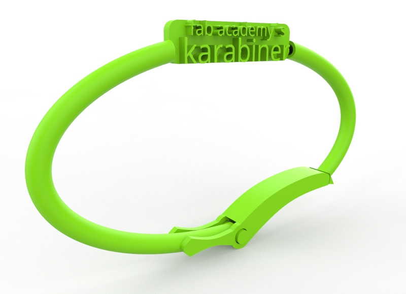
In printing the part, Cura pointed out that it could not print the lettering. I had it embosed thinking it might make it better for the printer to access it. It turns out the software was not able to pick up the lettereing at its original size.
Inside cura I scale this file x3 ~ in order to get the larger "karabiner" lettering printed. The smaller text "fablab's" was basically ignored due to its small size. You can see the render in green.
I later took a look at mechanisms that come out of the 3D printers working and I realized they mantain self supporting strucuters at the moment they are being printed.
Here is another round of printing the karabiner in the printer.
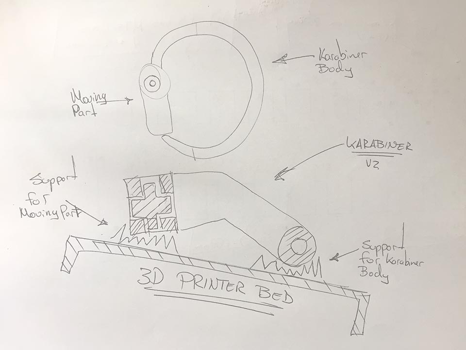
After drawing the kaliper v2, I decided to test it out with no support material, ideally so the joints dont get cluged up and the mechanism runs smoothly.
.JPG)
.JPG)
It did not work.
.JPG)
Here is the part printed with support material.
The following is a good example, where every component that will move is self supported at the printing time.The file file is up on thingiverse under "true szuare of fabric of thybes 2.0 by ChrisVZ and find it here.
Protecting the ISP
As a result of previus accidents, i also decided to create a case for the isp in order to protect it. As to utilize my time in crating new pbc's and not have them brake. With this inspiration I developed a case for the Hello world isp.
Following are the settings used in 3D printing
- Material PLA
- Profile: Fine -0.1mm
- Layer Height .1 mm
- Printing Temperature: 200 deg C / Build plate temp: 60deg C
- Speed: 60mm/s
- Cooling: Fan Speed: 100%
- Support: Generate support ☑ / Support Placement: Everywhere / Support overhang angle: 50<.li>
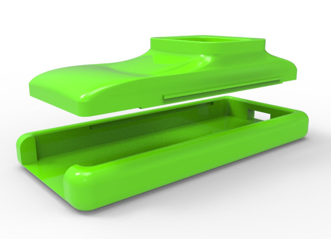
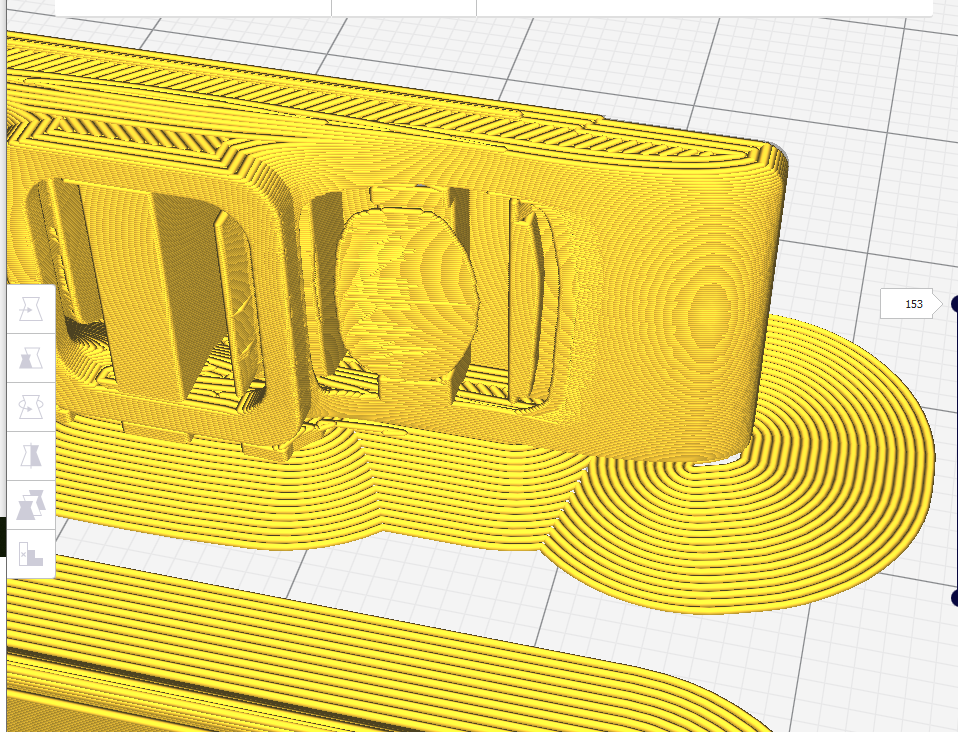
In green is the preliminary design. Its a base and a cover, with an opening for the 6 pin connector to plug into.
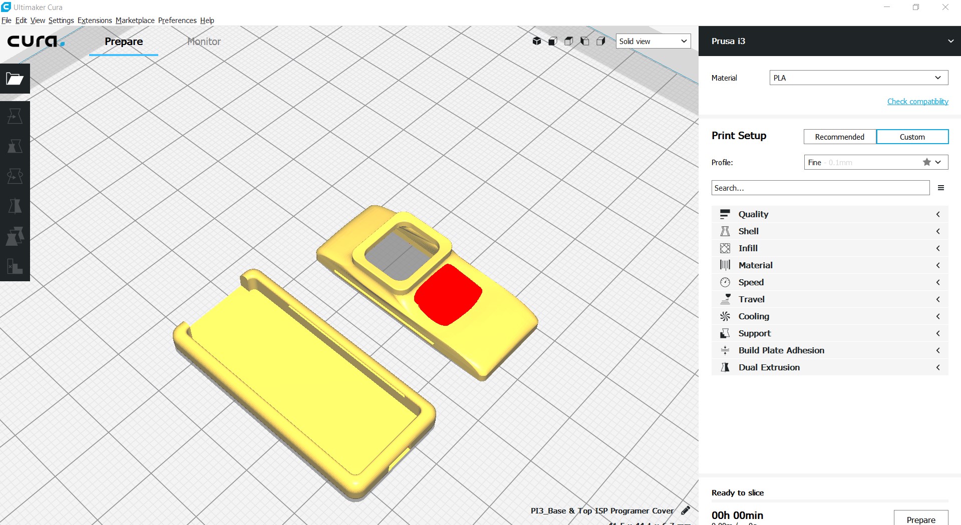
We later see the cura file prep. It showed the top of the cover in red. At the time I did not know what it ment, and shruged it off.
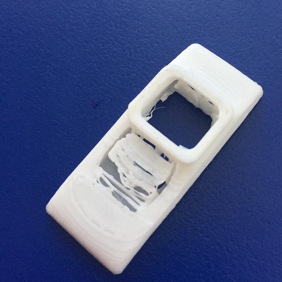
After the print it came out.. mostly printed. I can now interprate the red area as area the 3D print
My new hypothesis
Soemthing went totaly wrong on the exporting process, as the cura recognized the nicely formed part as 2 bodies. The wierdest thing ever. .
I actually made a fairly complex curvature I was proud of. The extruded probably cannot access without it's extruded touching its surrounding.
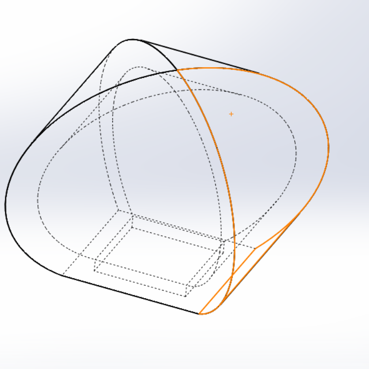
Designing the file:
In this case, I was hoping for a smooth nice surface on top and a a method to practice some of my compelx geometry in solidworks I have stated to forget.
In this case I actualy constructed the bottom extrusion, and the top extrusion of the to cover.
later creted profiles based on the ending bottom and top surfaces of the extrusions as planes and guide for the comming loft.
The after coping an entity on each outside profile of the extrusions, I used the right and front planes to create guides.
I later asked solidworks to use the entities as start and stop profiles for the loft, and to do so by following the guide lines.
Once this lofted surface was created, I offested the surface, somehow created a solid and joint it with both extrusions.
Possibly the longest modeling for a programming cover that didnt acutally fit its case.
For anyone outhere plannning on doing fancy cadwork as a practice hobby: get your measurements straight first, and simple shapes. The jump into the complex srufaces later.
The bottom cover, that actually is still in use was just 2 extrusions, one for the base and the next one for the walls. You know... functional. I guess it could of had some curvature continous fillets on the bottom, oh well..
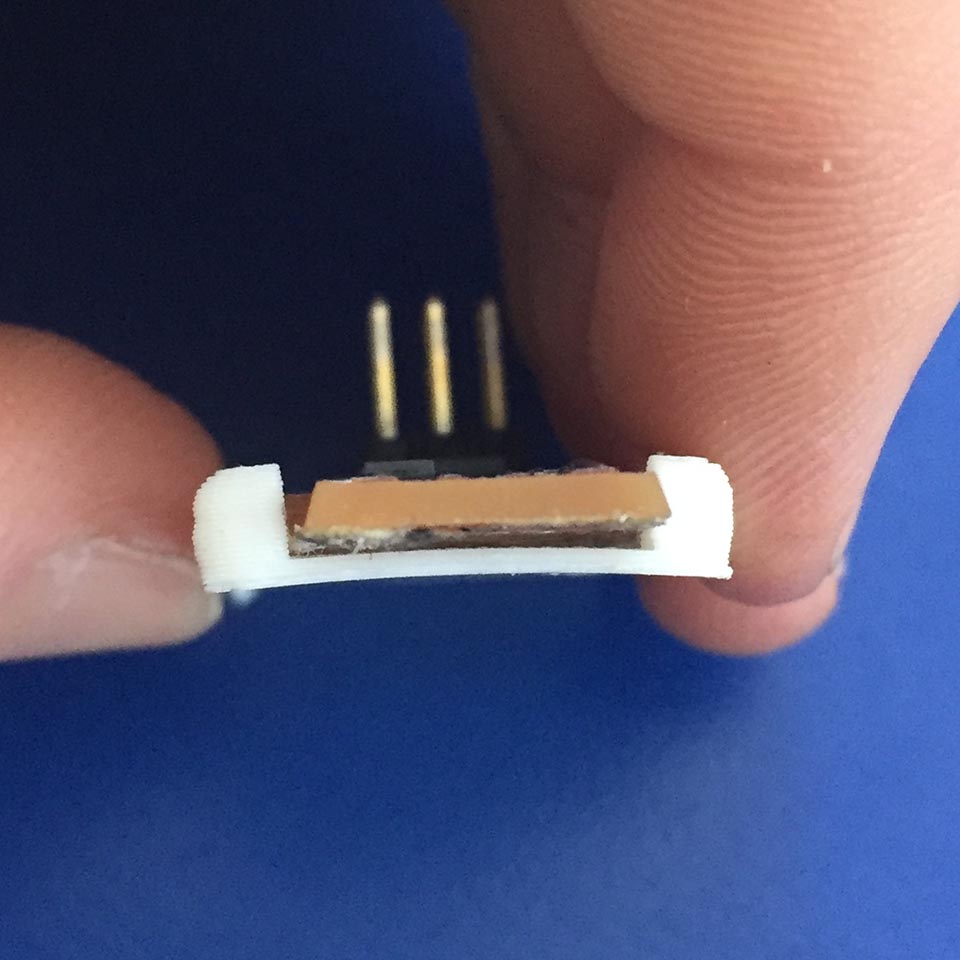
It looks like I should have left give in relation to the isp in order to properly fit. I left the dimensions exact to .5mm of tolerance.
It can be seen that in order to insert it, the plastic has to actually flex outwards. At the same time, the connector didnt fit either. It most lightly shrunk as well.
.JPG)
.JPG)
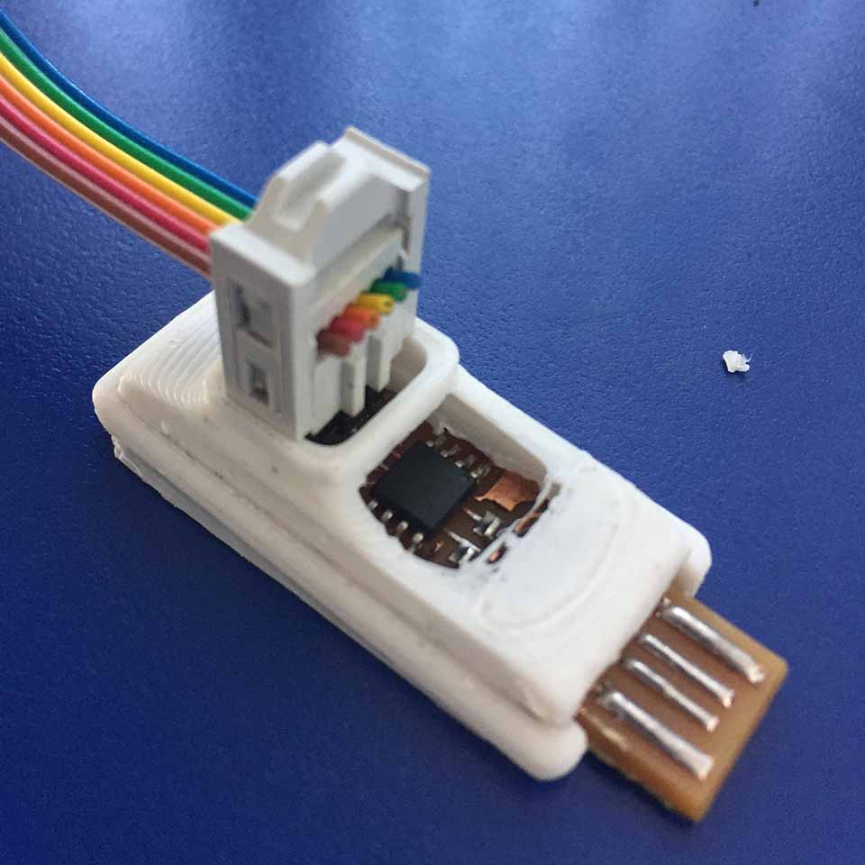
In this case I recreated the top cover of the isp part to actually cover the programmer. With a much more robust geometry consisting on a extrution, fillets, top access and a shelling operation.
The actual cover's base was +-0.5 mm tolerance, with the machine's presicion of +-0.01 layers.
Making a part with this acuracy on a traditional manufacturing method is just not accesible.
Think about actually getting that precise in a milling machine manually 20 yrs ago was just not accessible for the gernal population as it is today because of the elevated knowladge gap required for someone with engeneering tendencies to understand, let alone execute.
Debugging
In printing we found out at the beguinnning the printer was too hot, when we started printing all the groups individual prints. This was causing the parts to slightly bend.
.JPG)
.JPG)
.JPG)
When the temperature was lower the printing layers became much more stable. Because we caught this imperfection early on (in the support material) the final parts came out flawless.
3D printing: A manufacturing that cannot be done with 3-axis cnc
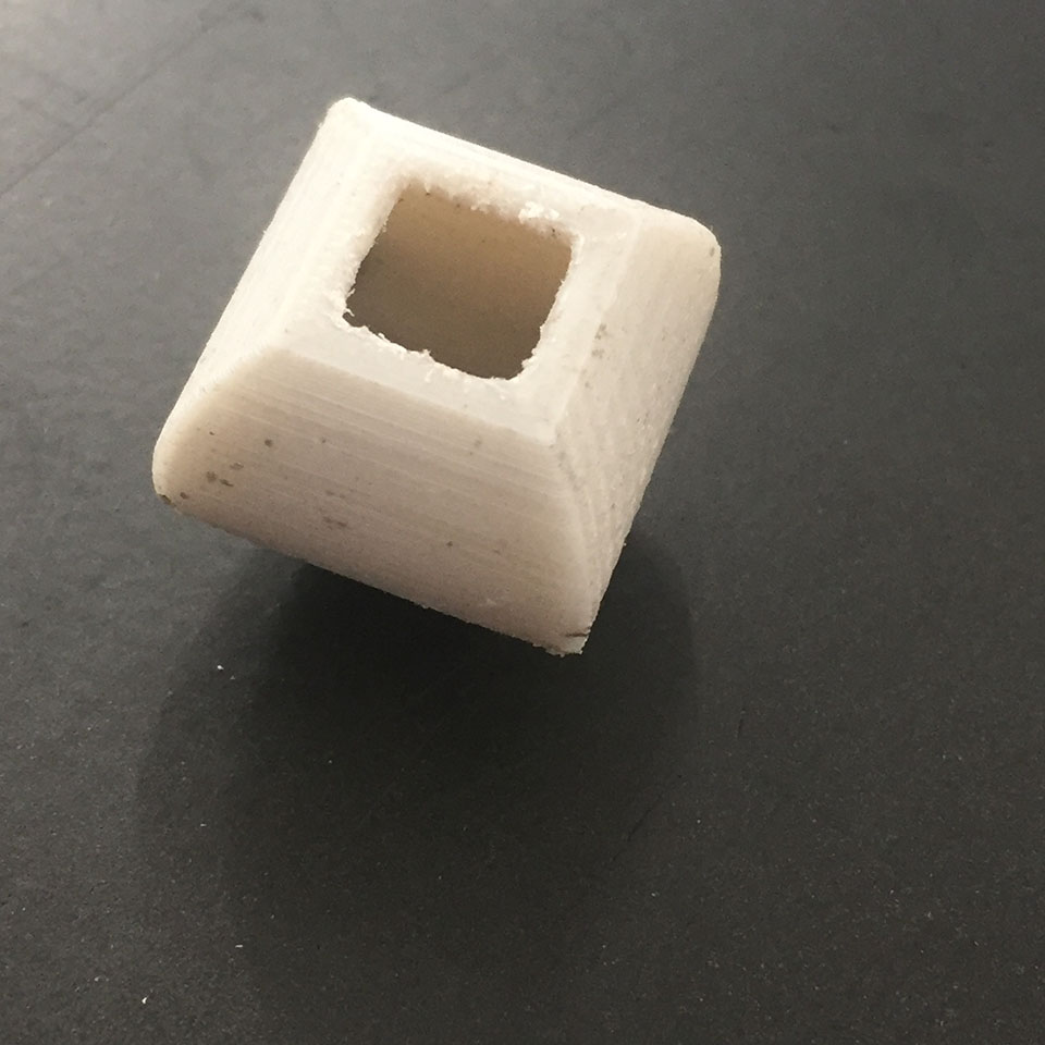
In this case I decided to do a part that diferenciates its self from other manufacturing methods by tacking advantage of the 3D printing additive process.
In this case I was influenced by Incredibly Satisfying Sphericons youtube video, By Maker's Muse where this person makes different spheroids. Objects that are not a sphere but will role similar to one on a flat surface.
So I looked to create something similar, a shape that by itslef could not be done by a 3 axis cnc due to the steep undercuts it has, where we see the support mateiral added by cura.
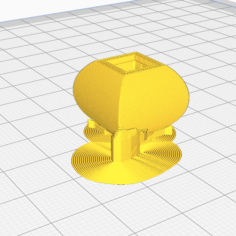
Aside from this, the actual spheroid was hollowed out on the inside. Another process a 3D cnc machine could not create as both it is limited by the isnide angle and the opening to get to this angle.
a good machinist will however find the loophole in order to create this shapes with multiple operations, yet this shape cannot be done with a single subtraction operation on a 3 axis cnc machine.
And as we can see, the 3D printer has no problem actually creating this part.
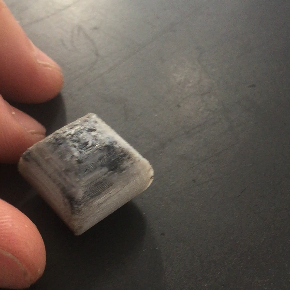
The black resedue on the top of the spheroid was due to some left over material from a previous print. If properly executed the selective color change cannot be done in a traditional operation either, but can be done with some pacience in a 3d printing operation. We can see this slightly on the part and more in depth on the youtube Video link above.
3D Scanning
Due to the nature of usign the xbox connect hack - we required multiple people in order to scan once self. The following are pictures of Alex and Danny scanning each other.
.JPG)
jorge By Jorge Correa Modelo
Here I share the scann file of my self: Download Here
In order to actually share the link I am required to upgrade inside the "Modelo" platform. Otherwise I can only share for 1 day.
As another addition, I played arround in order to scan stuff without the need for a x-box scanner. Specifically in order to user my phone. Neil talked about photos in order to scann stuff. One aplicaiton freely available in ios I found was Qclone
Supported in both ios and android, it was a very intresting tool to scann stuff. It consists in:
- 1. a phone to take pictures
- 2. a base print, similar to a QR code, or possibly one all together.
- 3. Lots of pacience and fiddling arround.
.png)
Here I am downloading this app. I also printed this qr code in an A4 paper Here you can have a look at this "QLone Mat"
.PNG)
Once you place it on the table and start "scannig" the software actually will crate a half dome, divided into parts indicating all the angles that require for the 3D scann to work. When captures, the cuadrant will turn from translucent to transparent
.PNG)
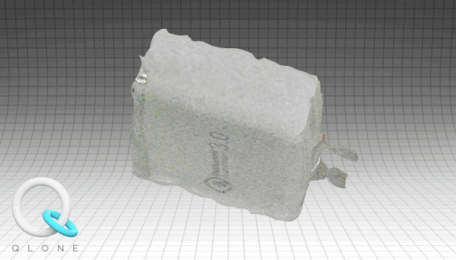
When all this is done, the software will compile it automatically into a 3D part.
.PNG)
The software concludes into letting you explore what the actual scann looks like. Its by no means really hi resolution. And If you dont have proper light then the final result becomes distorted and pixelated (as mine did) But you can add more half-dome scanning and it will compile the part with more data, creating a higher quality scan.
In order to fully export is as a obj. you have to earn credits and pay and stuff. I was able to export it as a gif freely:
To Conclude
3D Printing
Group Assignment In the group assignment we saw many problems that are not shown in the common trouble shooting guides. 1. non continually recurring problems as stringing might be. 2. the final surface is top notch. The bottom portion is not. This might be a slight overextrusion that in most cases only benefits the overall part quality. It looks like it also compensates for the printer's limitations: on a controlled environment and layer resolution resulting in the underside of the print to turn out that way.
Individual AssignmentIt was a good excersise as it forced me to evaluate the 3D printing process. It was a great exersise to find out what things could go wrong. As I found as part of the group test part "*MINI* All in one 3D print test file by Marian Trpkos" many problems that didnt really apply yet is good to be well aware of. Doint the individual assignemnt later provided with great information in what could be possible.
In the object had to be 3D printed, as the v2 version has movable joints. Other production methods cannot have movable parts from the get to. Aside object cannot be produced with a perfectly hollow center inside as the 3d print has done.
Joints cnanot be directly manufactured subtractively, hence this part could not possibly be done other way than 3D prntning.
3D Scanning
In this scanning process, we see how simple and accesible 3d scanning can be. It is a very complex object to scann a person. In relationship I would not know where to start modeling an organic shape as it. With some tweaking of the process it cvertainly becomes geometry so close to actual person and useable 100%. Im glad we made this excersice.
As a side note, the Qclone was a cool way to scann stuff. Still you see that it requires time in order to get usefull mesh objects, and is still not free to use. Its a developing market, and as such is a good thing that everything is charged so it is .. in theory .. further developed into better tools for scanning. More time = better results, its a fact in life. Hence it is also something to be furthre developed for my self.