Project Development
Assignment List
- Final Prject Development ☐
- Documentation ☐
- Final Working Model ☐
- Blueprints and Delivrables for open source production ☐
- To Conclude & Reflect ☐
What is the deadline? how much time do you have left?
| June 12: Final Project Presentation |
|---|
| June 19: Last date to submit for review in this cycle |
| June 26: Last date for feedback from review |
| July 3: last date to submit review feedback |
| June 10: last date for decision in this cycle |
| December 1: Restart cycle |
What tasks have been completed, and what task remain?
Task complited are:
| electornic production |
|---|
| 3D scanning |
| Electornic Design |
| Computer controlled machining |
| embedded programing |
| Input Devices |
| Output Devices |
| Netweoking and communications |
| Wildcard Week |
| Invention, intelectual property |
| project development |
| Final Project |
How will sI complete the remaining tasks in time?
I literally have no time left. My plan is to pull through with share will, and if I finish is because I had enough to beguin with.
I have not much time to plan, I will start myself from the later weeks and move up to earlier ones.
My instructor has advised me better than this with a proper plan, but I have not followed it at the end. More experiance comes more judgement im sure. 1 Assignments a day was his plan. Right now I have to do more like 6.
What has worked?
Base on results, what has worked best is possible machine week. It was an assignment we started looking over it weeks in advance and we assigned each other specific and quantifiable results.
If I take what has worked, as that week and apply it to thre current state of things: Ill first revise what is required of me and later on expand on to what is a bonus. Ill keep track of it all through noeval.
What has not worked?
Doing the documentation after the actual week has finished is basically what mismached my entire schedual.
There has also been more than one things that has lead to a dead end and was not fully docmuented as its final conclution leads to nothing. Yet not mentioning could potentially make me make the same loop again.
Time based management has not worked in most cases in my procedure as in most scenarios the learing process takes more time than expected, until fully understood.
What questions still needs to be answered?
Q1: How to integrate the time into the coffee making system?
Q2: How long would the battery actually work inside the chair, and how to get it to constantly be charging in acordance to its limitations.
Q3: Can it be a reminder to consider the water/coffee setup? Idealy could that be automatized?
What have you learned?
The most valuable leson learned from this experiance, asisde from the time management issue, is the accesibility that all the integration of "smart" sensors and ALU I actualy have at my disposal. With this the ability to agregate value to products and things arround me, in order to help and actuate acurate data.
Coffee production probably will never be fully dependent of somebody being sitted or not on a chair, but humans and the internet will have much intrest on sensing when and how humans are interacting with their environment in a quantifiable way: thats what I'll be taking with me.
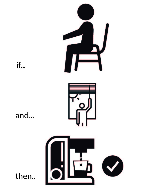
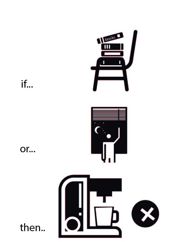
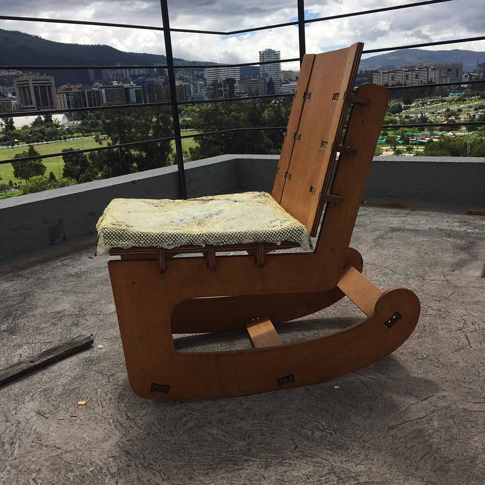
The goal:
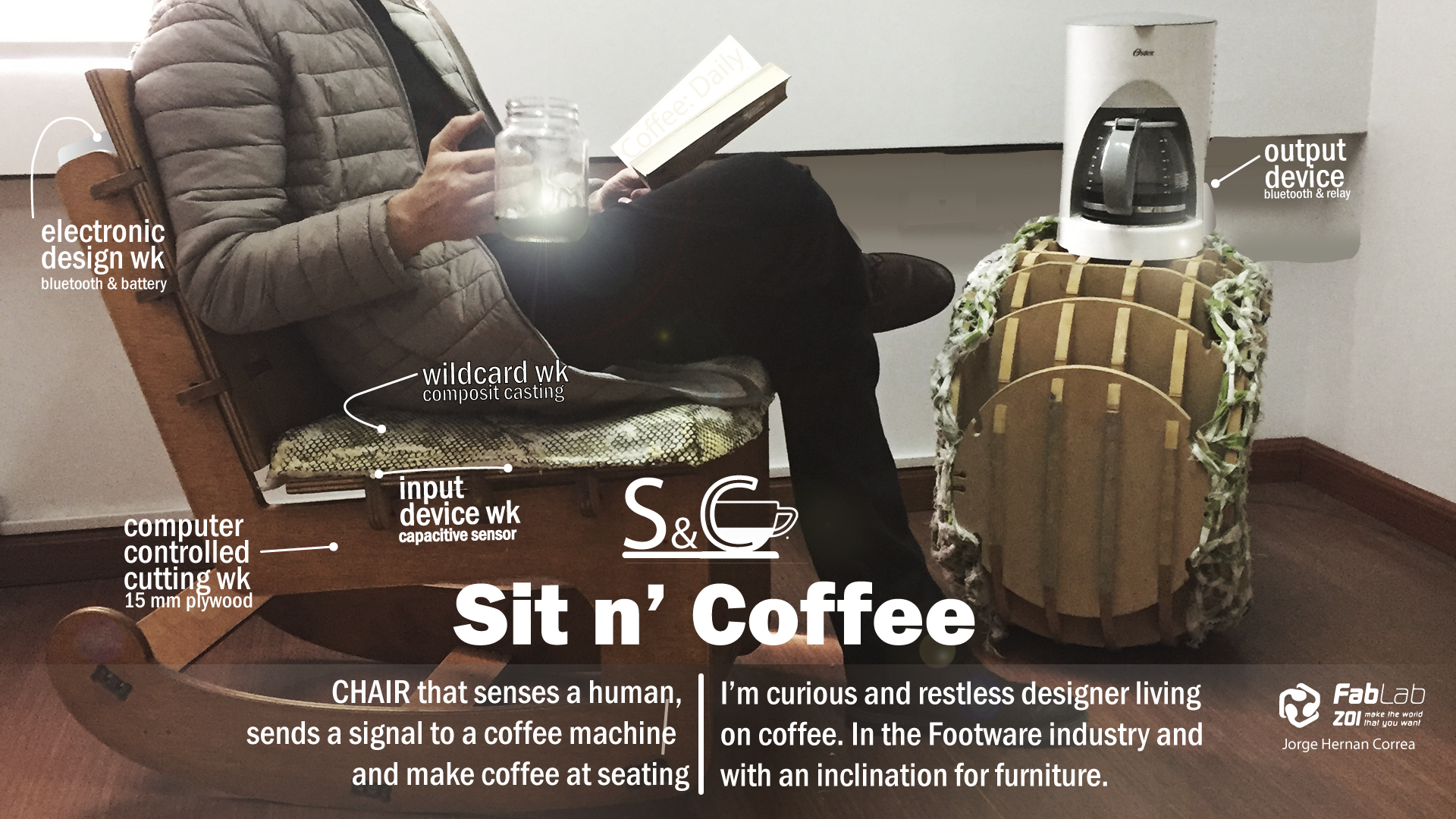
Create a office chair, that makes you coffee after you sit down first thing in the morning.
The method:
Create a desk chair, that senses a person, senses that it is morning, that it has not made coffee yet, and will make you coffee.
Why?
Because I am a coffee lover, and this is the first thing I do when I start working. Making a setup where a machines does my first daily action will both inspiring and filling each morning.
Integrating the digital aspect of production as not to require any aditional process is also magnetically intresting to me.
Current version of the project
The weekly update on working towards the final project:
computer-aided design
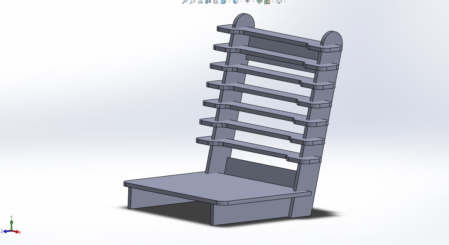
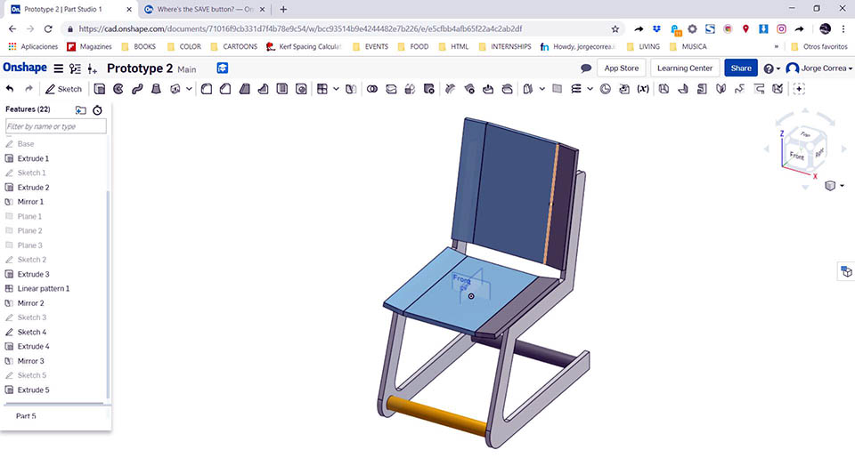
In this week I explore a couple of concept I had running though my head about possible dimensions, and consturction structure. Not really getting into the snap-fit details of it all yet.
With it I reconnected with softwares I had not used in a while and new cad software that become strong oponents by basing everything on the cloud.
Have a closer look at pros and cons I found out
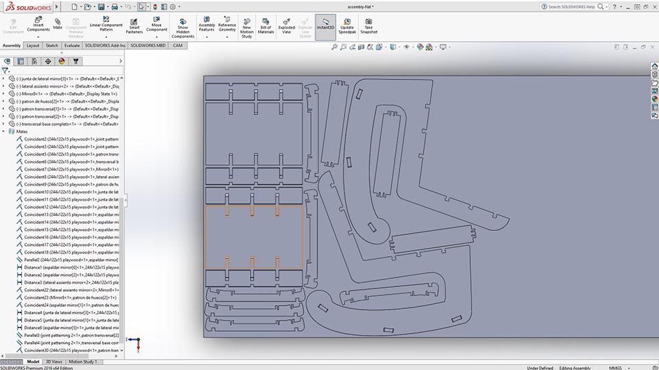
computer-controlled machine
.JPG)
.JPG)
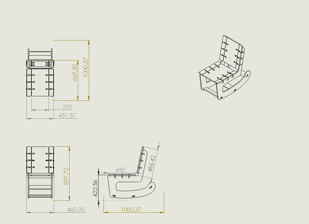
In this week the final concept was developed, modifing it into a whimsical concept of a rocking chair.
I have not documented, but I did a finishig process between the final project
| Quantity | Component Description |
|---|---|
| .5 ltr | Brown wood stain: dyluted in paint thinner about 1:5 ratio. Applied before finishing |
| 2/3 ltr | Linseed Oil |
| 2/3 ltr | Paint Thinner |
| 2/3 ltr | Water based Varnish |
The Linseed oil, paint thinner and water based varnish where mixed. With this new mix 2 coats where applied with a 24hr window in between coats.
A final Sanding was applied with a 22 grit sandpaper.
The final result was like so:
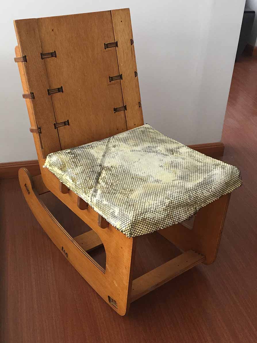
look closer look at the protoype, cutting bits and all that good stuff
Electronic Design
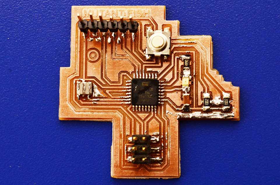
This bad boy actually made it to the final project accidentally. As I maxed the memory and broke my Attiny44 for final imput device. Aparently its a riskey move to use your microcontroler at 97% capacity.
The first electronic design process had my back
Modling and Casting
.jpg)
.JPG)
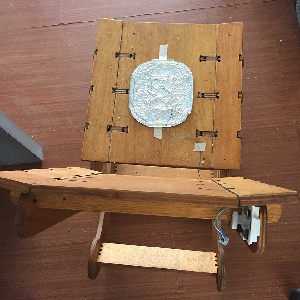
This decorative insert never really worked well in the cnc casting process. It would not fully stay on while rocking in the chair.
I include it for the process of trail and error not for the end result, as I have opted to exclude it from the final presentation.
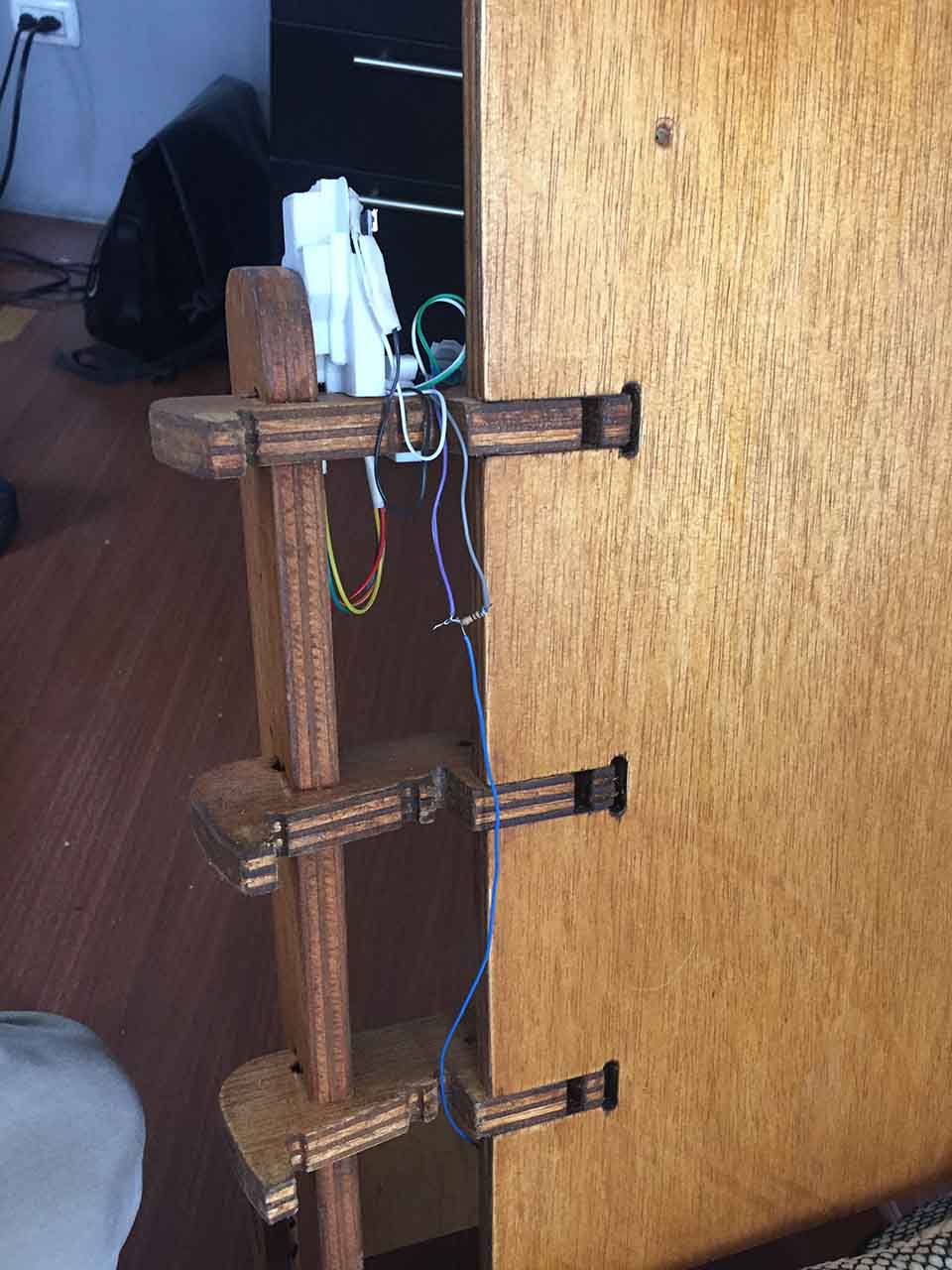
Casting plastic covers for wooden joints
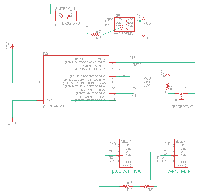
Input Device
This case I was proving the concept that I can get the capacitive sensor work.
Py GUI never got it working in my computer, I later decide to see see the reading though the arduino port. It was no recognizable. So I switched into the aruino's library.
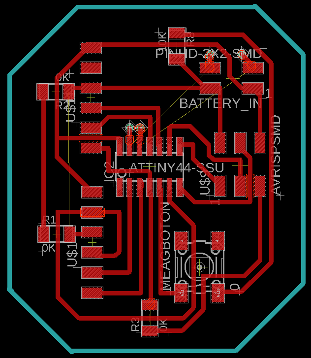
Bill of Materials
| Quantity | Component Description |
|---|---|
| 1 | Attiny 44 |
| 2 | ftdi port 1x5, female |
| 1 | isp 2x3 pin port, male |
| 1 | 2x2 pin port, male for power |
| 1 | button |
| 3 | 0 ohm Resistance |
| 1 | 10k ohm Resistance |
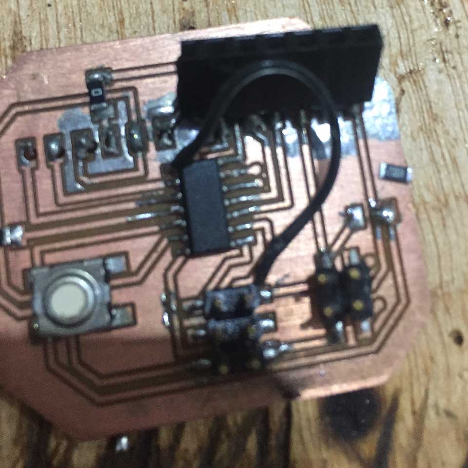
In this case, at the debugging state and advised by Ale found some buggs in the pcb syste. 1. The vcc was not plugged in so we had to place a jumper cable. 2. The button was not poorly place in the system, so I removed the 10k resitor and connect the pin to gnd.
Its all raw data from a 10k resistor, into the arduino.
After a couple of tests about different materials, a flaten aluminum tray from a lasagna was the best choice.
In this case After setting the parameters of how high sensibility a person is read in the sensor, it was time to standarize. Into a swich, 1 or 0, ON or OFF.
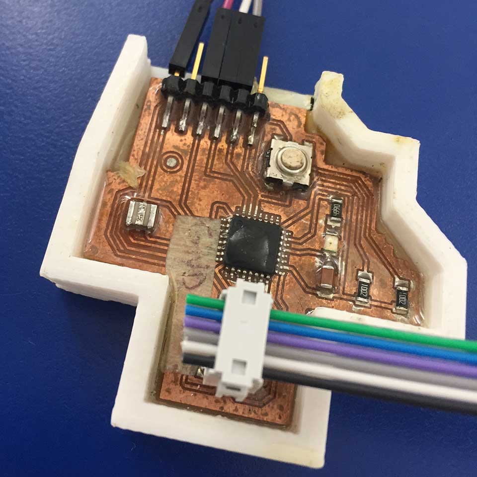
This was the original pcb Input based on a Attiny44. After the working code was developed, the microcontroller got 97% memory full and broke down.
I decided to instead work with an earlier version of a pcb. With a bigger microcontroler: Atmega328p, from the Electronic Design week.
Testing and understanding the input capabilities of the capacitive sensing device.
I stray apart form the capacitive sensing library only to go back again to it and make the system work for it.
The process behind the Input device
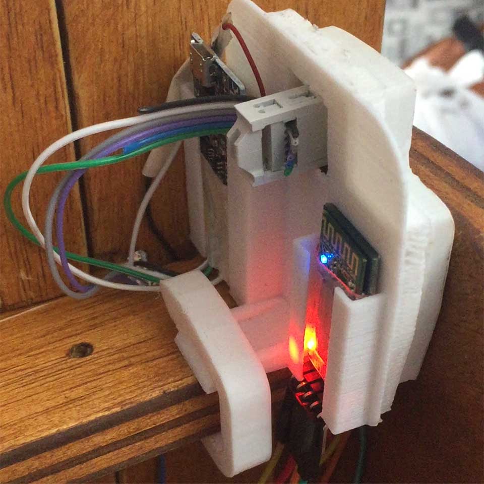
Output Devices

The week 12, I used a relay to acctuate the coffee machine to my bitting. In this case I swithced the machine ON and OFF with a timer set to the Attiny 44 microcontroller.
Here I am testing this loop, prooving that I can control the machine this way but that the relay will not fry with the 8amps of current going through it.
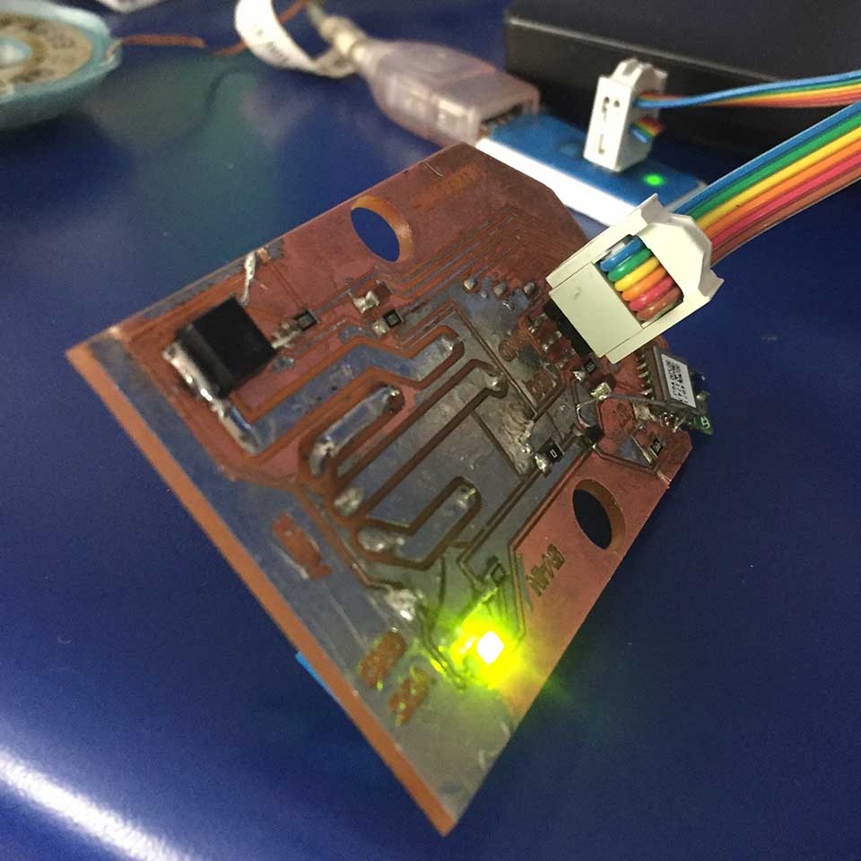
This simple video shows the intended output pcb at work. In this case I am sending a 1 or a 0 through the serial port connection/ftdi. The end results in the realy clicking everytime the proper impulse is sent.
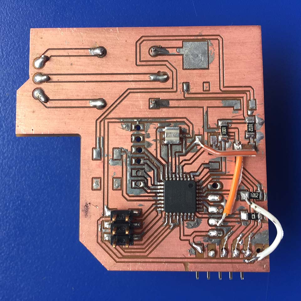
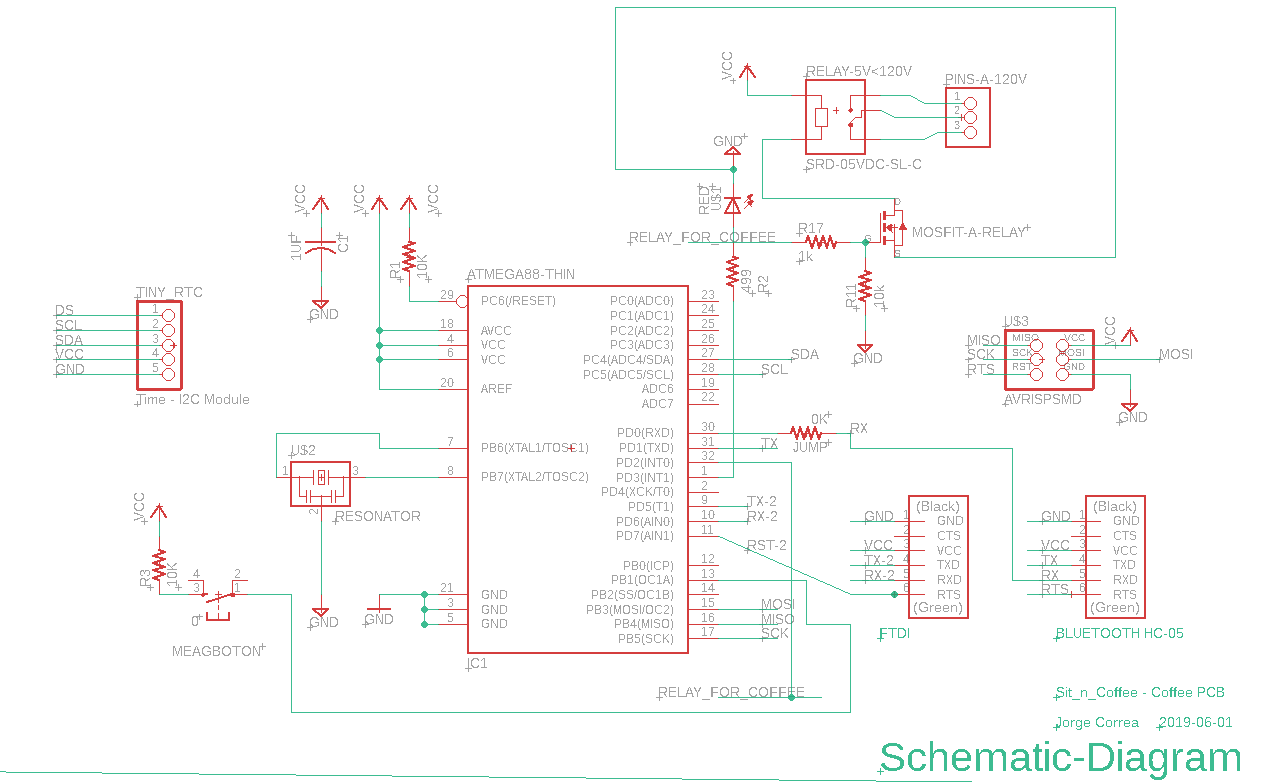
Here is the actual pcb, again I was forced to to create a bridge or three as a result of missing connections. 1. In this case the Reset was not fully connected to the ISP pins. 2. The capacitor was not not connected to gnd 3. vcc was not connected to the RTC output for a clock integrated in the pcb.
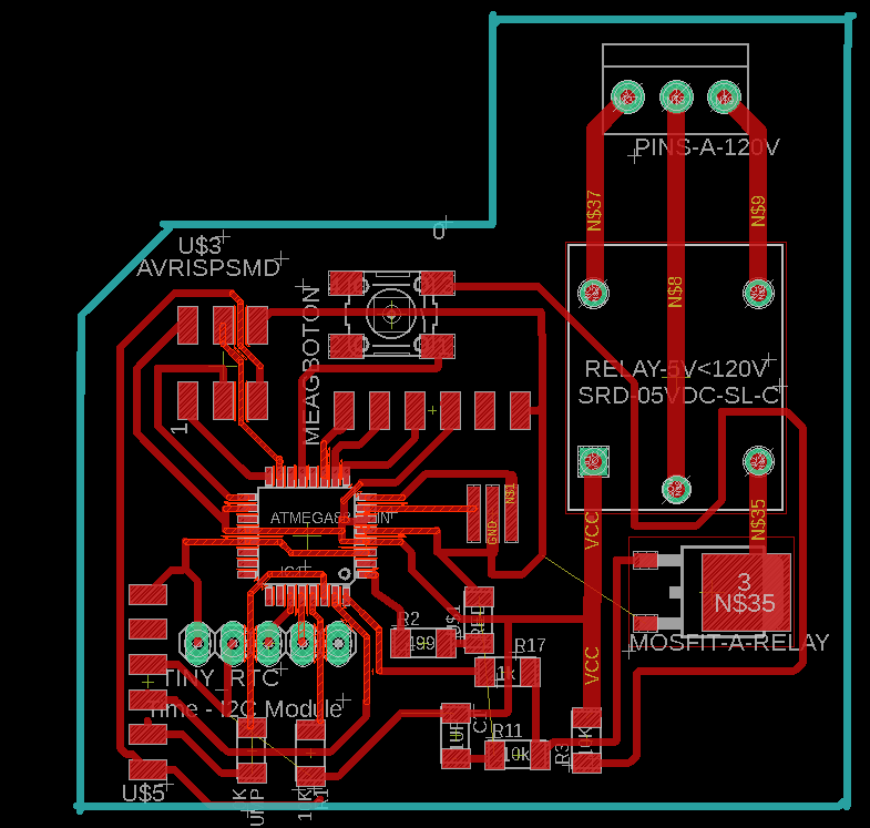
Bill of Materials
| Quantity | Component Description |
|---|---|
| 1 | Atmega 328p |
| 2 | ftdi port 1x5, female |
| 1 | isp 2x3 pin port, male |
| 1 | 1x5 pin port, male for RTC Clock Mdoule |
| 1 | button |
| 1 | Mosfit |
| 1 | Relay 5V -120V / SRD 04VDC-SL-C |
| 1 | screwable pin inputs for relay / 120 v connections to the coffe machine |
| 1 | 1 uf capacitor |
| 2 | 1 k resistor |
| 1 | 10 k resistor |
| 1 | 499 k resistor |
| 2 | 0 k resistor |
In this case, at the debugging state and advised by Ale found some buggs in the pcb syste. 1. The vcc was not plugged in so we had to place a jumper cable. 2. The button was not poorly place in the system, so I removed the 10k resitor and connect the pin to gnd.
Networking
In this area, it was always planned to connect through bluetooth.
Initially I had planned and executed a couple of pcb's containint the rn4871, but I never got it to work
Input PCB: (week 11)
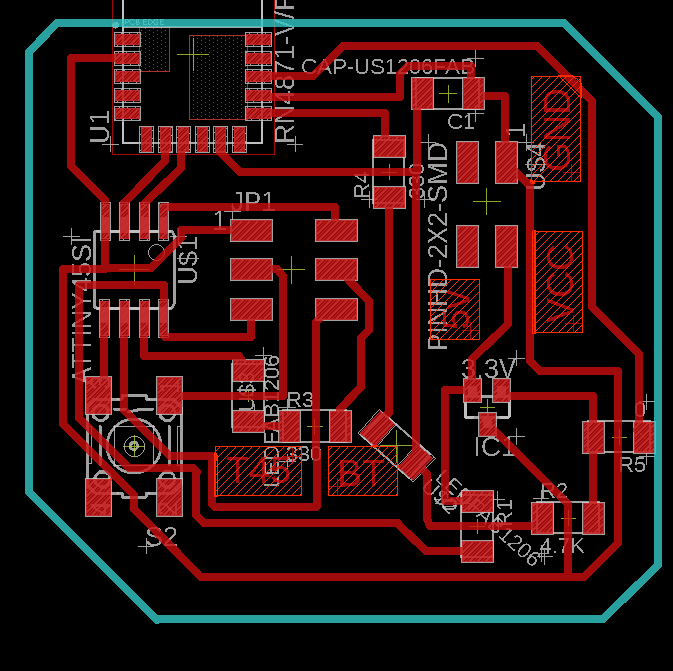
BOM:
| Quantity | Component |
|---|---|
| 1 | Attiny 44 |
| 1 | RN4871 Bluetooth module |
| 1 | Button 6mm |
| 2 | LED Light SMD |
| 1 | Capacitior 1 uf |
| 1 | 2x3 pin ISP connector, male |
| 1 | 2x2 pin connector, male |
| 2 | 330 ohm Resistance |
| 2 | 0 ohm Resistance |
| 1 | 3.3 v IC |
| 1 | 4.7 k Resistance |
Debugging
In this case, I figured out later on that the bluetooth vcc was not connected and I required to jump a cable.
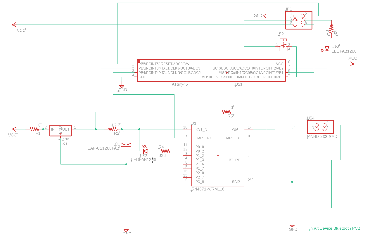
Output PCB: (Week 12)
In this case, the main reason to produce this pcb was again to prove that the relay would turn on and off the coffee maker. Ideally It would have also carried out until the final proejct. Unfortunately It was not possible.
Debugging:
the bluetooth's vat was not connected, by this point I had already gotten good to create unplanned brdiges, so I used an un-used edge to do so.
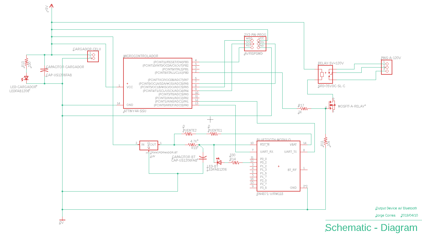
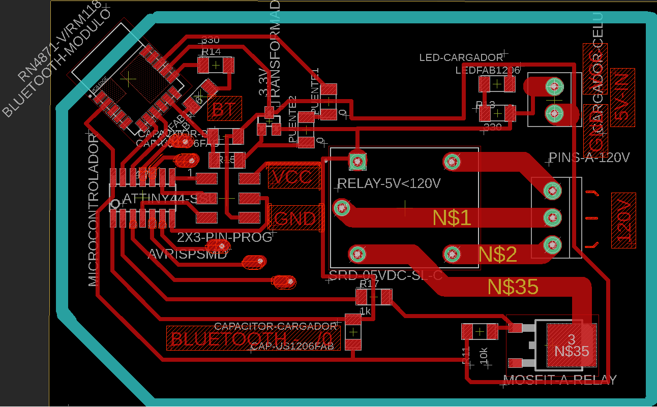
BOM:
| Quantity | Component |
|---|---|
| 1 | Attiny 44 |
| 1 | RN4871 Bluetooth module |
| 2 | LED Light SMD |
| 2 | Capacitior 1 uf |
| 1 | 2x3 pin ISP connector, male |
| 1 | 2x2 pin connector, male |
| 1 | 330 ohm Resistance |
| 1 | 10k ohm Resistance |
| 1 | 0 ohm Resistance |
| 1 | 3.3 v IC |
| 1 | 4.7 k Resistance |
| 1 | Relay 5v - 120v "SRD-05VDC-SL-C" |
| 1 | Mosfit "NMOSFETTO252" |
I later found out that the input current from the 3.3 vIC electornic component might have been wrong. After close inspection it outputed closer to 4.7 v.
The last debugging hypothesis regarding the issue with the rn4871 bluetooth is the change in voltage might have damaged the module, but it not lightly as 5v is a standard voltage that a bluetooth would be equiped against.
The following links are usefull guides:
Aparently one of the biggest points to take into consideration is that the module wont return a response on most commands, only ones specifically instructed to do so.
In order to actually program this bluetooth, it was the following steps:
| $$$+ | Enter command mode |
|---|---|
| PZ | Clear all services |
| R,1 | Reset module, take effect all the changes |
In order for it all to take effect, you are required to reset the bluetooth everytime.
I ended creating another pcb, this time the pcb offered for the class in the Networking week.
.JPG)
.JPG)
I never managed to move past this stage, So I switched to another system:
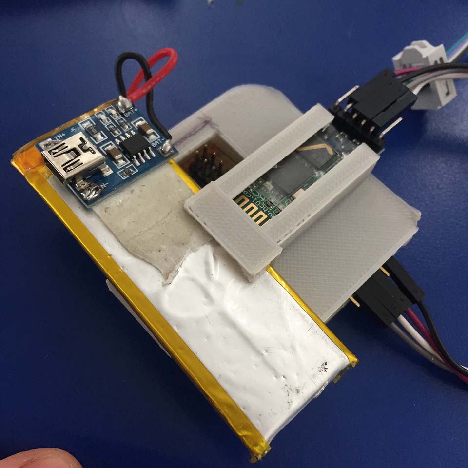
HC-05 Bluetooth module.
HC-05: The setup
First make sure you have the hc-05 and not the hc-06, as the 06 is not able to become a master and so it required a 05 first. Physically diferenciated with a button on the buttom.
Before connecting the HC-05 you have to press and mantain the reset button, so the module enter command mode.
Once you have done so, Open the serial port, in this case arudino's port to communicate in the right 'com' port.
| 38400 | Baud Rate |
|---|---|
| Carriage Return | Set |
| AT | Response= OK // Cheak if you are connected |
| AT+RESET | Response= ok // In order for anything to take place |
| AT+UART=9600, 0,0 | Change the band rate into a certain number |
| AT+UART=9600, 0,0 | Change the band rate into a certain number |
| AT+NAME=S-C BT M | //sets the bt name (Master or slave ) |
| AT+ROLE=0 /* OR */ AT+ROLE=1 | //Slave or Master |
| AT+CMODE=1 | //"enables the search for available devices"-Danny Vallejo |
| AT+PSWD=1122 | //Sets password |
| AT+RESET | // Resets the module and makes the changes active |
The setup, FTDI & HC-05
HC-05 & HC-05
It is required to setup one HC-05 as a Master, and one as Slave.
Once I actually got them sync, I could actually transfer data between them.
I later opened two diferent terminals: Arduino & Terminte 3.4 (due to its ease of installation and light weight)

Communication:
| HOLA |
|---|
| SIII |
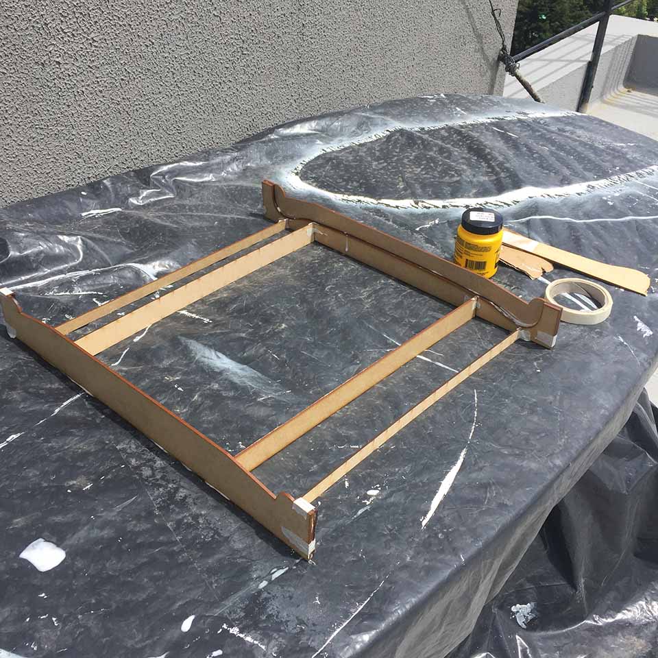
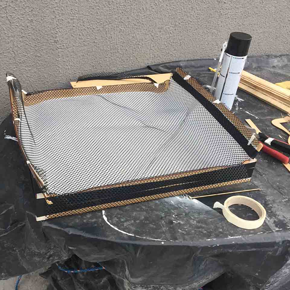
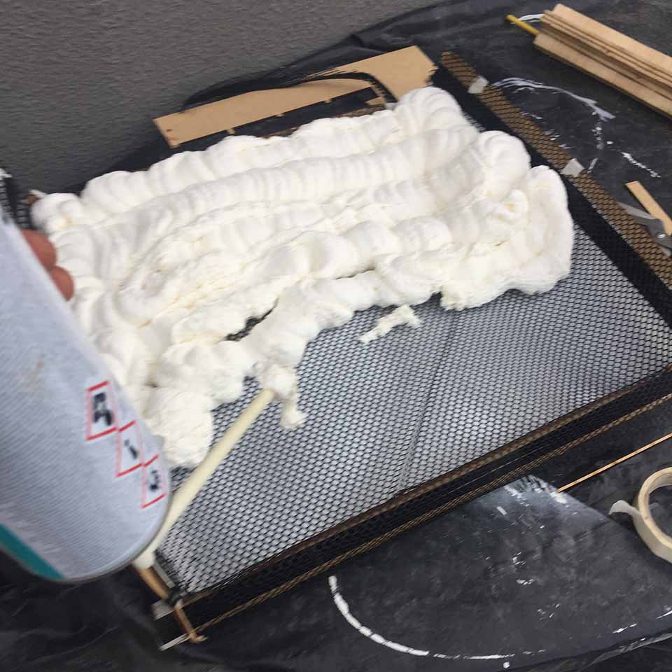
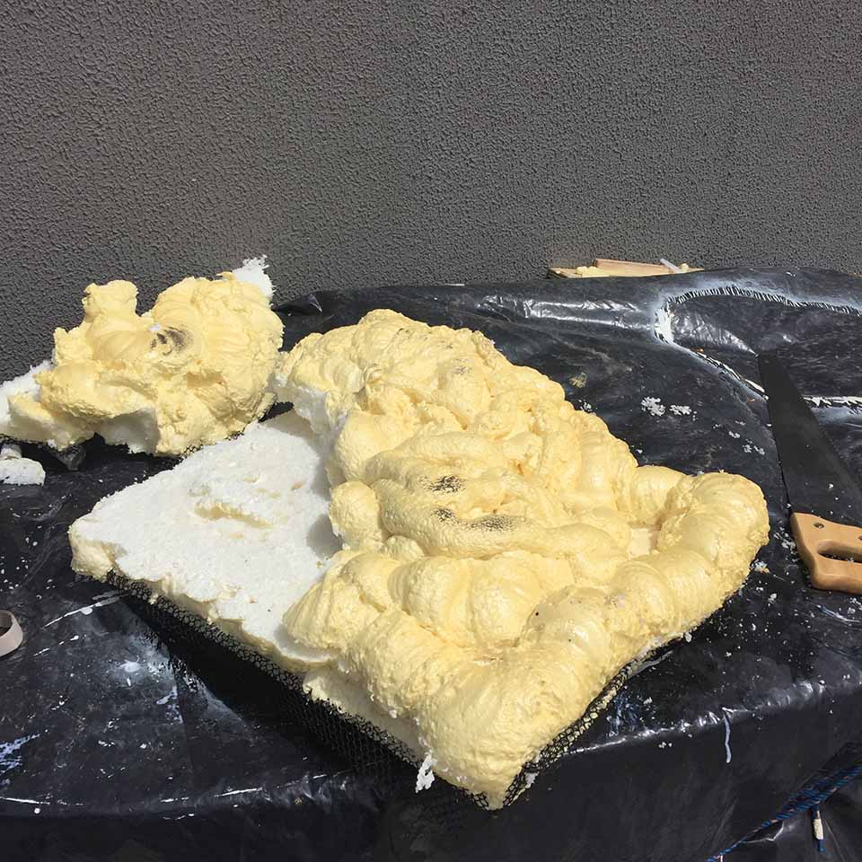
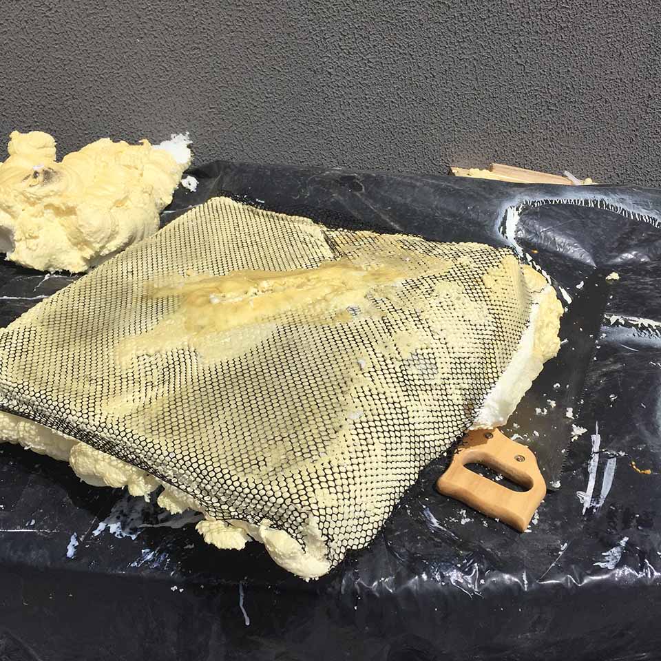
Wildweek
For a wildcard week project, I decide to create a simple mold with a mixture of PU and an open mesh polierter textile.
Final project development
In this stage, all the components where already working in their own space, and had to bring them all together.
The constructive aspect of it, was already worked around, in this case it became the code joining both pcb's.
For the output:
For the input:
// Relay pin is controlled with D8. The active wire is connected to Normally Closed and common
int relay = 2;
volatile byte estado = LOW;
char incomingByte = 0;

// Timer Variables
long lastDebounceTime = 0;
long debounceDelay = 10000;

void setup() {
  // Pin for relay module set as output
  pinMode(relay, OUTPUT);
  digitalWrite(relay, LOW);
  // PIR motion sensor set as an input
  // Triggers detectMotion function on rising mode to turn the relay on, if the condition is met
  // Serial communication for debugging purposes
 Serial.begin(9600);
	}

void loop() {

if (Serial.available() > 0) {
incomingByte = Serial.read(); // read the incoming byte:
Serial.print(incomingByte);

if ((incomingByte)  == '1'){
digitalWrite(relay, HIGH);
   // Serial.println("ON");
  }
else {
digitalWrite(relay, LOW);
//   Serial.println("OFF");
	  }
	}
 delay(10);

	 }

 //  CREDITS: Rui Santos: Complete project details at https://randomnerdtutorials.com
#include 'CapacitiveSensor.h'

CapacitiveSensor   cs_4_2 = CapacitiveSensor(13,11);        // 10M resistor between pins 4 & 2, pin 2 is sensor pin, add a wire and or foil if desired
const int numReadings = 10;

int readings[numReadings];      // the readings from the analog input
int readIndex = 0;              // the index of the current reading
int total = 0;                  // the running total
int average = 0;                // the average

void setup()
{
   cs_4_2.set_CS_AutocaL_Millis(0xFFFFFFFF);     // turn off autocalibrate on channel 1 - just as an example
   Serial.begin(9600);
   for (int thisReading = 0; thisReading < numReadings; thisReading++) {
	readings[thisReading] = 0;
  }
}

void loop()
{
	//long start = millis();
	long total1 =  cs_4_2.capacitiveSensor(30);

//smothing code, by David A. Mellis  'dam@mellis.org'
  total = total - readings[readIndex];
  // read from the sensor:
  readings[readIndex] = total1;
  // add the reading to the total:
  total = total + readings[readIndex];   //readIndex variable to imput
  // advance to the next position in the array:
  readIndex = readIndex + 1;
  // if we're at the end of the array...
  if (readIndex >= numReadings) {
// ...wrap around to the beginning:
	readIndex = 0;
  }

 // calculate the average:
  average = total / numReadings;
  // send it to the computer as ASCII digits

//Serial.println(average); //USE THIS TO CALIBRATE

 if (average > 50)
  {
	Serial.print('1'); // ln solo para humanos
  }
  else
  {
	Serial.print('0'); //
  }
	delay(10);  // arbitrary delay to limit data to serial port
}
/* * CREDITS: * CapitiveSense Library Demo Sketch * Paul Badger 2008 */
To Conclude
Fun project, and increadibly fulfilling. Documenting what I actually did fully was important in order to develope on it further.
Everythign takes al least twice as long to make execute and ideally planning for that error is good practice, and sane advice. I still impres myself everytime Im programming a pcb I made myself with a self made programmer just as well.
Aditionally the support created by the documentation on my own website (dont thing any other fabacademy support) makes a much more fluid review and reflection of what could be done better and what needs to be improved.
Making another cycle of reiteration much easier to actually implement. Is a system that could bring much joy in the future.
Wholistic Perspective: It is possible the load of the project on my self was a proper one, even whith uncertainties of what actually could be done in the beguining the scope was an excelent bucket. Much of what I have seen I can apply, and the system could potentially be very intersting just as well for further development. I had great guidance with my instructors, as Im sure I would have not pulled it off in a remote location or without direct contact.
It was the right amout of complex and became a managable size. I possibly only regrate not documenting earlier.