Input Devices
Assignment List
- Group Assignment ☐
- Measure the analog levels and digital signals in an input device ☐
- Individual Assignment ☐
- Measure something: add a sensor to a microcontroller board that you have designed and read it. ☐
- To Conclude & Reflect
Group Assignment
For the Digital signals, I was hopping to measure the capacitance of something. As I was looking for deeper dive on to the capacitance knowledge.
A quick internet search told me to measure capacitance with the "capacitance" option on the multimeter. Turns out this setting is not as common as I first envisioned.
Or at least my multimeeter did not have it.
Because caacitance is "the ability of a system to store an electric charge" a normal multimeter will not read how much a capacitor will actually take in charge. There is however a way.
When the miltimenter is set to contact setting, it will send out charge. When connected to the capacitor the charge will be absorbed by the system.
Depending on the size of the capacitor, it will take different amount to charge it.
What I show is
Given, my multimeter is basic, due to me being out of the fabacademy at the time.
Based on how much time elapsed, it is possible to determine the capacitance value of the system without reading it from the component. In the given equation: t = R * C,
- t = time constant
- R = resistante in ohms (presumably to limit the rate at witch energy flows in)
- C = capacitance in farads
The general theory beind all this I read from here. An electronics-tutorial.
Im finding it very tough to actually measure acurately the time from when it starts to when it stops charging. And currently the 1000 uf capacitor is the biggest one I have at my disposal. It was an intresting experiment no the less.
- 1000 uf / 5 ohm = 200 time units
- some actual engeneer took it and left me without the real value.
but if I had to guess: 524.5 uf / 5 ohm = 104.9 time units - 49 uf / 5 = 9.8 time units
Individual Assignment
In the individual assignment I got into undersdtanding the capacitive difference sensor theory.
The theory:
The idea is that current flows, through every coductive surface and that by doing so create a very week electromagnetic wave.
We as humans, are as well creating the most tinny electromagnetic wave around us.
With this, whenever a human limb gets closer to an electro-magnetically charged surface it disrupts the status quo of its magnetic field with its own.
In the following circuit we detect this aditional pulse over the pulse already created with the current filling the charge objects.
The earlier in short is my interpretation of how a capacitive sensor works in theory.
The practice:
I followed a tutorial and actually created a very simple circuit using and arduino, to prove the theory behind the touch sesonr. See the video below.
I used the following equipment:
- 1x Aluminum foil
- 1x 1M ohm resistor
- 1x Arduino uno
- 1x Connection cable
- 1x LED Light

Image and code from hackerster, by amal mathew
#include

CapacitiveSensor   cs_2_4 = CapacitiveSensor(2,4); // 1M resistor between pins 2 & 4, pin 4 is sensor pin, add a wire and or foil

int in = 2;
int out = 4;
int state = HIGH;
int r;
int p = LOW;
long time = 0;
long debounce = 200;
void setup()
{
  pinMode(4, INPUT);
  pinMode(8, OUTPUT);
}
void loop()
{

  r = digitalRead(4);
  if (r == HIGH && p == LOW && millis() - time > debounce) {
    if (state == HIGH)
      state = LOW;
    else
      state = HIGH;
    time = millis();
  }
  digitalWrite(8, state);
  p = r;
}
Installing the actual library was an unexpected troubleshooting I had to do. I ended downloading it from : here, the arduino playground
Find the source Tutorial by Amal Mathew showing: Touch Controlled Light Using Arduino
In this subject, knowing your resistors was key and as a result I found 2 helpfull calculators.
In the end, I know I'll fully grasp the resistors by memory, but before that is nice to have I think less to look up or debug.
I later on go to expand this principle of capacitance, and measure a couple of more things.
Initially to make sure it works, I end up to the point of connecting a flattend lasanga aluminum platter, with a 10k resistor directly to some of my Mutant Fisn PCB, done Electronic Design, and actually start getting a digital signal as so:
After this, I do keep on measuring.. as a result of a certain upcomming final project to be finalized.
In this case I use a capacitive.sensing library that is fairly common and been loyal to me, and in it I tweek a couple of parameters i detail later on in the Project Development week. I did want to share :
One of the closer measurement in the capacitive sensing that lead to the chair having proper sensibilites. The following shows the capcity with 1 hand, 2 hands, sat down and proximity, when somebody walks arround the chair creating that noise.
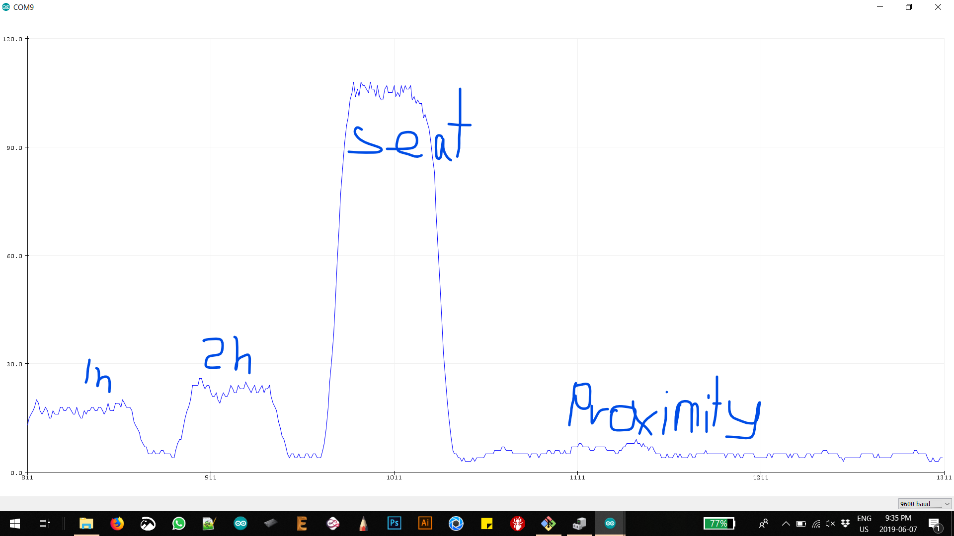
The actual wire/ resistor connection that follow up unto the bluetoth module pcb, actually also pick up capacitance, letting the sensibility have 2 points of interaction and being much more acurate in its measures.

.JPG)

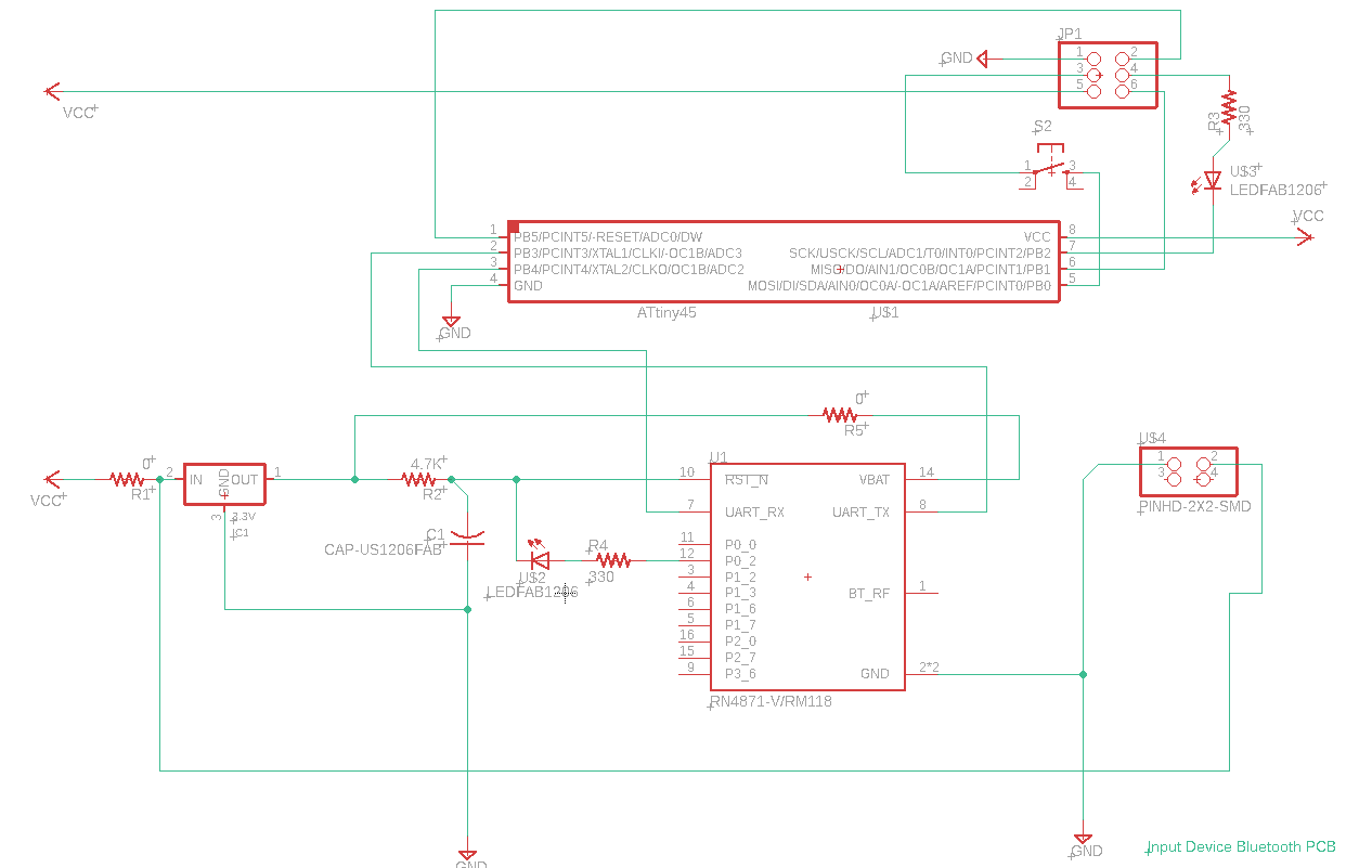
The input pcb
In this case I was planning to use this pcb to send data into the other end, throught the bluetooth module
Not certain what Input I was actually going to use I initially thought to use a button. Latter discredited because I was actually interrupting the isp input. I added the VCC / GND as seperate pins in order to later actually use the isp pins as something else.
Reading up on the new bluetooth component
.jpg)
.jpg)
drawing the schematic, and later found out the auto-path tool. Fun to play arroudn with, and when it works but its only good for small simple boards.
.jpg)
I finalized my design as so:
.jpg)
.jpg)
I had a terrible missalignment, when exporting the png, as the selected area was much larger and I attemped to manually cohencide the boards later. It didnt work. I manages to test ti before in the NC-Viewer online fortunatly. You just drop your code in.
I was combining my cutting code and paths to see if they cohencide. On the right I later figured out you move the artboard limits manually, so I did that.
.png)
.png)
So I created this:
.JPG)
.JPG)
This is what happens when you wait for after the debugging. A filthy board happens.
In this case I also used the arduino library we talked about earlier, but directly from the examples.
Also using a 1k resistance, that is why we see nex to: long total1 = cs_4_2.capcaitiveSensonr(500).
I belive the original recomendation the examples gives is a value of 30. In the end a 10 k resitance and that made all the difference.
This PCB actually did work for a bit. I unfortunately did not get a video, and later on the fab actually took most of its components in order to create neil's capacitive sensor pcb, and the bluetooth for the rn4871 as part of the debugging process.
#include
#include
SoftwareSerial ftdi(1, 6); // RX-1(pb0) | TX-1 (pb1)
/*
 * CapitiveSense Library Demo Sketch
 * Paul Badger 2008
 * Uses a high value resistor e.g. 10M between send pin and receive pin
 * Resistor effects sensitivity, experiment with values, 50K - 50M. Larger resistor values yield larger sensor values.
 * Receive pin is the sensor pin - try different amounts of foil/metal on this pin
 */

//2= capacitive connection
CapacitiveSensor   cs_4_2 = CapacitiveSensor(9,10);        // 10M resistor between pins 4 & 2, pin 2 is sensor pin, add a wire and or foil if desired
//CapacitiveSensor   cs_4_6 = CapacitiveSensor(4,6);        // 10M resistor between pins 4 & 6, pin 6 is sensor pin, add a wire and or foil
//CapacitiveSensor   cs_4_8 = CapacitiveSensor(4,8);        // 10M resistor between pins 4 & 8, pin 8 is sensor pin, add a wire and or foil

void setup()
{
   cs_4_2.set_CS_AutocaL_Millis(0xFFFFFFFF);     // turn off autocalibrate on channel 1 - just as an example
   ftdi.begin(9600);
}

void loop()
{
   // long start = millis();
    long total1 =  cs_4_2.capacitiveSensor(500);
  //  long total2 =  cs_4_6.capacitiveSensor(30);
    //long total3 =  cs_4_8.capacitiveSensor(30);

  //  ftdi.print(millis() - start);        // check on performance in milliseconds
    //ftdi.print("\t");                    // tab character for debug windown spacing
    /*if(total1 > 200){
        ftdi.println('1');
      }
     else{ftdi.println('0');
     }*/

    ftdi.println(total1);                  // print sensor output 1
    //ftdi.print("\t");
    //ftdi.print(total2);                  // print sensor output 2
    //ftdi.print("\t");
    //ftdi.println(total3);                // print sensor output 3

    delay(100);                             // arbitrary delay to limit data to ftdi port
}
How the datasheet helped you
in this case I actually was short of a couple of pins for the integration of this "mutant fish pcb" into the actual system of the chair. because the bluetooth connected to the ftdi side of the pcb, took up all the rx and tx pins I was forced to establish serial ports and replace the mosi and miso pins into being used as input pins.
In order to do this I used the datasheet in order to pinpoint what the miso and mosi pins (PA3)(PA4) and define them into becoming new tx and rx pins in order to recive and send data.
Measureing the Analog Signal
In order to measure the analog signal I used the Osciloscope, and after watching some tutroials on the matter, attemped to try out a bunch of arduino Example codes. Including the blink, and step motor controller.
The most demostrative was a fade code for an led. Because It shows the wave cycle wider and narow as well as as the voltage change acording to the led turning brighter or dimmer.
the actual code can be found: HERE
To Conclude
This week was a nice advance for my final project, as it determined what type of relay I need. At the same time it was a productive time to soak in about capacitive theory. It is certainly the most apropiate input for the final project and one of the most intresting in my eyes as well (a nice combo).
It also gave me a deeper understanding of the capacitance units farad, and a deeper dive into that whole new concept.
I regret not starting off with my pcb board "mutant fish" for this project as it is something ill eventually do.