Embedded Programming
Assignment List
- Group Assignment ☐
- Compare the performance and development workflows for other architectures ☐
- Individual Assignment ☐
- Read a microcontroller data sheet. ☐
- Program your board to do something, with as many different programming languages and programming environments as possible. ☐
- To Conclude & Reflect
Group Assignment
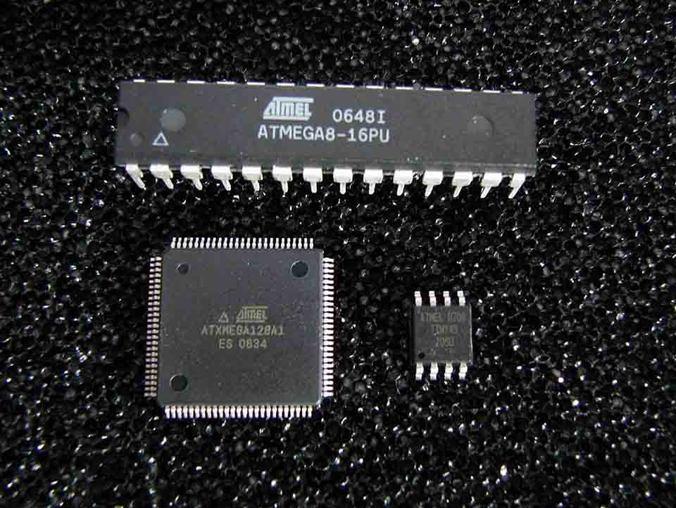
image from wikipedia: Article Microchip AVR
The different arcitectures
- Harvard
- von Neumann
- RISC
- CISC
- Microprocessor
- Microcontroller
- FPGA
- CPLD
- spatial
If for example the architecture is a house, the harvard system has multiple rooms that send "people" to be adding room (CPU). But they always have to be simultaneously walking. By having multiple "rooms" for "people" to walk between its more efficient but harder to organize.
The von Neuman Architecture instead has 1 central room where all the people go in and out of. In this case people can be instruction people or outside data people, sharing the same room. Bu having one room its easier to organize "people" walking to and from "rooms" but it becomes less effective.
(Reduced instrIt closely resembles a command in a higher level language. For instance, if we let "a" represent the value of 2:3 and "b" represent the value of 5:2, then this command is iuctions set computing) In this case, the microcontrollers work in a much ridmic fashion. Where every instruction is broken down to sets of only 1 instructions and are operated acording to the internal timer. One instruction at a time. This tech emerged later than the CISC, because it brakes down instruction it performes in a better controlled time frame. Some very specific reference contrasting the tech with CISC
(Complex instruction set computers) Is a generation of microcontrollers or a specific architecture within that processes a higher level code into assembly by inately creating complex code lines in assembly that direct the information into the registery and later main memory. Creating little for the compiler to complile and organizing data into micro-size-specific degistable bits of code. Another source contrasting the RISC to CISC
A microprocessor is an electornic compoent focuses only in computing operations. Another name might be a ALU and would be found inside a Microprocessor. Easy to get confused in the beguining, the microprocessor also does not contain any memory to work with or clocks or anything aside.
The microcontroller does contain a microprosseor inside, as well as memory, possibly a clock, and imputs and outputs that work acoridng to all the components contained inside.
(Field Programmable Gate arrays) semiconductors devices that connect via interconnects and work arround matric of data.
(Compled programmable logic device) A logic device in between super customability (FPGA) and a very rigid device ment only for a specific process (PAL).
Int he context is how all the components intertwine in between one another? I found little to no reference of a specification in the realm of microcontrollers especifically.
Individual Assignment
Read a microcontroller data sheet.
Program your board to do something
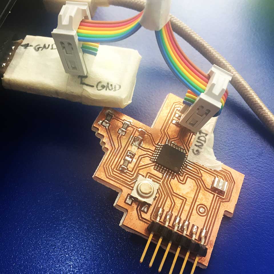
In this section we are going to program the isp boad done in week 5 and the pcb board done in week 7. In this case we will need the following.
- The FabISP Programmer board
- 6-Pin 2x3 Header connetor bet
- The pbc board from week 7 (mutant fish pcb)
- the FTDI Cable
The easy way (arduino)
The first step was to understand what we actually had to create in oder to actually wirte, what to write inside the atmega microcontroller. We had to aquire 3 things:
- 1. Aquire the fuses in order to properly configure the microprocessor
- 2. Find the Microcontroller's name to actually adress it in all future instructions through git.
- 3. Find the correct pins the pic is connected to from the schematic in order to adress it and program the atmel with them in mind. I decided to program i C and aduino cause I didnt really know how much harder it was.
- Getting this things we are able to program the pcb to do something. Like blinking the light.
The fuses: I understood them as a gate keepers for certain rooms to enter inside the Atmega processor depending on what "guests" you might plann to invite into the microcontroller. So for example if Ill be using a 20 hz ozolator (Ext. Crystal Osc; frequency 8,0 - Mhz, start-up time PWEDWN/RESET: 258 CK/14CK + 4,1 ms;), and will require to reset the microcontorller at some point (un-check "BOOT REST")
.jpg)
The final Output we find under Current settings as hexadecimal digits. In this case:
- Low:0xE2
- High:0xD9
- Extended:0xFF
The above digits will prime the microcontroller to work in the way it should require. "open the correct doors"
Below Im entering the Hexa code fiuses in order to set the microcontroller up. We later upload this code into the microcontroller and later we actually the controller into doing what we need.
.jpg)
.jpg)
To find the Atmega 328p code to set up the .make file, we search the git with the following command: "avrdude -c attiny45 t" that is telling the microcontroller's current operating system to tell what are all the code equivalents devices it could read.. and we find Atmega328p = m328. We replace this code to the Attiny45 previous code.
.jpg)
Insert part where everything was not cool and i had to redo de microprocessor pbc
In order to find if everything works properly, I opeed git. And typed : avrdude -c attiny45 -p m328p
In this case I strugled because the behaviour of the git ansers where erratic, It started as: avrdude.exe:
"AVR device initialized and ready to accept instruction
later it showed: "ardude.exe: initialization failed, rc=-1
I looked over the fuses, and got nothing wrong. I had forgot to copy the bootloader files inside the arduino directory.
.jpg)
After that It was still not working, and it was strange as everything seemed in order. I took some drastic measures and: 1. Re-installed the Arduino IED 2. Gave the Mutant fish a Bath in Alcohol (in case something might be messing the connections.) With close help of alex the ISP finally programed the Mutant PCB.
As a result of this de-bugging the final program was finally working.
I have added the code used for the blink.
					        #define F_CPU 2000000UL  //Frecuencia de cristal
#include  <avr/io.h> //libreria para entradas y salidas
#include <util/delay.h> //call librari that you are able to create delays

#define retardo 1000 // define variable
int main (void)
{
	/* set (PB5) of PORT for output */
	//DORB = (1<<PB5)
	DDRC = (1<<PC0); //configura como salida

	while(1)
	{
		PORTC = 0b00000001; //se enciende el led
		_delay_ms(retardo);
		PORTC = 0b00000000; //se apaga el led
		_delay_ms(retardo);
	}


}
To Conclude
This assignment became a dense acumulation of other prohjects before. I did have to recreate the pcb in order to complete this assignment. Part of the reason why I'm actually encompasing the Hello world pcb In the video. The excersie was vast and the final execution slim and simple. It is however a large pilar that later projects will sit on. I/o Is comming along and having a clear understanding for it is a crutial step.
I wish I would have started by actually reading the AVR tutorials, and having the click that "Embedded programing" refers to programming that is embedded inside the microcontroller.
Seriously, avr tutorials became a great resource to refresh my memory on what I actually do and have a deeper understanding of what the programming parts actually takes place.