Machine Week - Mechanics
Assignment List
- group assignment ☐
- design a machine that includes mechanism+actuation+automation ☐
- build the mechanical parts and operate it manually ☐
- document the group project and your individual contribution ☐
- To Conclude & Reflect
Machine Design
This week we required to create a Machine. Looking at the good work of previous generations it was a no brainer to build on top of it, make it better, and our own in a way, while still giving for the next generation to create on top.
In this case, the <strong>ZERO CNC</strong> is a concept developed based on our positioning in the globe (equatorial line) and developed into the concept of a zero point, inside the head of the machine. Point 0,0,0. Where the machine is actually pulled form the center to its axis, by the motors. This becomes an advantage in simple mechanics, eliminating all the gearing systems and only have 2 guides (1/2" rods) and 1 screw per axis hooked up directly into the motor. A no shenanigans CNC machine.
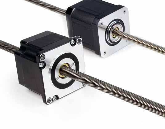
As a nice add on (an incredible forseen by The Zoi team) ordered this screw based step motors we got some weeks earlier to work on this project.
This is where the person would seat in order to activate the coffee machine.
Have a look at this demostrative video of the motor function, How to Use Through-type Lead Screw Stepper Motor (81062)
And this much cooler video of one of this stepers being taken apart: 3D Printer stepper motor mod
Anyhow, the previous generation had a snug fit on regular step motor positioning, as can see in their documentation. With this through mechanism we set out to out-shrink them. In this case I got assigned the actual head of the machine. Positioning of the motor in space. Fun!
I had a couple of iterations that did not look right. Where I was looking at working on the 3 axis simultaneously, but it was really not the way.
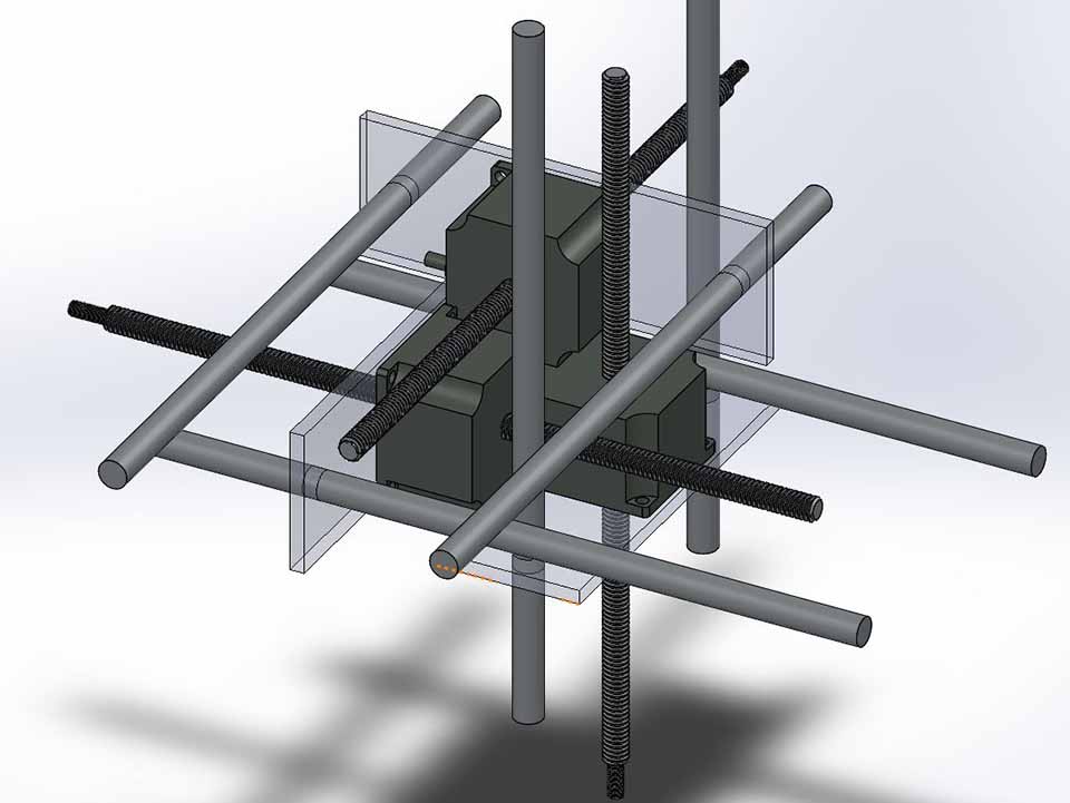
It was not until I cut my losses and actually developed into a system where, the x and y axis where as close as possible, an latter added the z axis. Talked it over with my mates and instructors extensively before I got the v3.
The concept was to actually show off the lack of mechanism with a glass box surrounding the 3 intertwined motors with a 3d printed part. A part that otherwise would have been too complex already for a student like myself to drop it out in some days.
I was so convinced this was my final i did some renders:
.jpg)
.jpg)
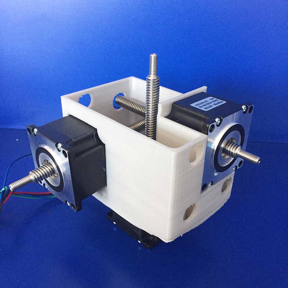
Printed the center part out. That took about a day.
First try had too much infill (50%) so we stoped it.
.JPG)
But the fit was great, as was I happy about it.
Assembled it as so:
the 3 axis where met to hold the z axis as part of the mechanism. They where not properly holding the screw, yet used the extra material as guide.
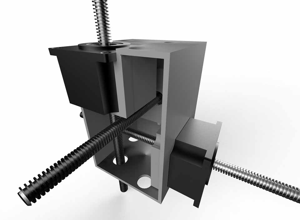
This sprung a great idea, what if we could integrate everything the Cnc required in a single print. So we did that instead an scraped the acrylic casing.
.JPG)
This beautiful 500g block of 3D Printed PLA became the result of this unifying concept for the Zero's CNC's Head. It took approximately 2 days and 17 hrs to print, lol.
Modelo single
Modelo assembled.
Depicted in blue for visual expression. We see how the blue 3D printed part it holds the nylon inserts and create a almost non existent friction with the 1/2 in rods. This inserts where kept from last year's Zero CNC and form an invaluable part of the simplicity of this mechanism, centering the rod, giving it 2 pints of support on the ends of the part. This nylon inserts had to have been lathed due to tolerance issues last year's group most lightly suffered for.
.jpg)
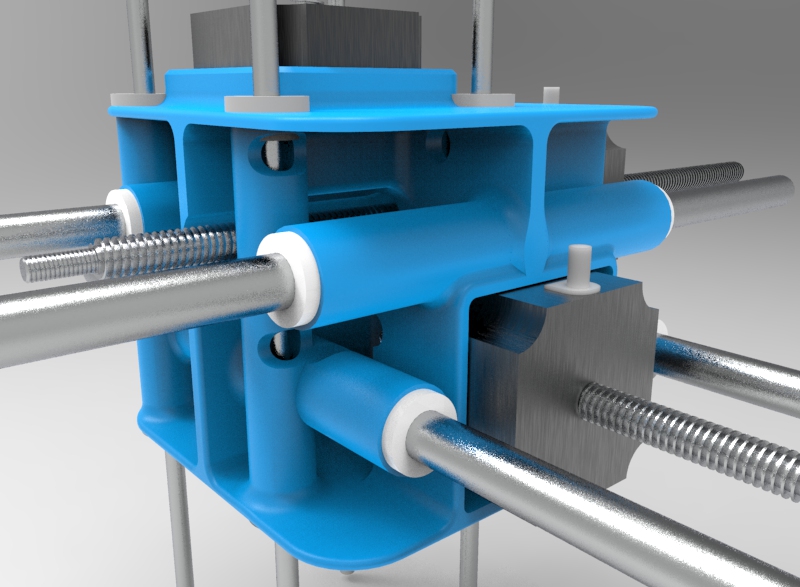
The extra holes that are seen are actually access points for the hexagonal screw driver that fastens the motors in place, against the 3D part. When have a 10 cm long screwdriver that was explicitly designed for.
.jpg)
.jpg)
The Step motors where consciously not fully submerged so that the cabling is flexible enough to be re-directed as we still figure out what side is up and what is down. Removing all the support material is something I hope I never have to do again.
The actual part was basically done thinking of maintaining the ribs on the center. as this part detergent from the last part is much larger, the ribbing should be placed in the center of the structure, to attempt to hollow out everything else. The full process was to split the part in 4 with a surface, hollow each part individually with a 3mm wall thick parameter and later joining all parts.
.jpg)
Finishing up with filleting everything. This process was only done to the x and y axis. If done to the z axis it would have been the perfect match but to do so I should have done this process again probably. I'm sure there is a much simpler process, but have not though of it.
.JPG)
This is the part fully assembled, with half of the z axis also in place. The test was to look for incongruencies in the axis line-ups with the production systems done with Danny. Nothing to get worried about, and later we tested the sliding capabilities as a group that was most satisfactory.
Here is a nut insert concept we played around as we brainstormed the best method to fix in the step motors to the 3D printed part without interference to the rest of the parts.
This part would have not been possible another way than 3D printed, in a reasonable amount of time. There is always the lost wax casting technique, yet otherwise carving a similar part out of wax might have taken more than the fab academy as a whole.
To Conclude
In heighnsight the part was and became a very interesting iteration in my opinion but still requires to be polished up. Things like actually producing a part where no support material is required so the material is cut in half, as well as actually reduce the required material for the head while not compromising its structure. Properly guiding the cables is another aspect that require further analysis, the current soluting is affording for them yet avoiding the problem all together.
The other revision also consists of fully integrating the spindle as a conscious part of the machine and not a motor attached to the bottom of the Delrin's sheet. Not doing so will be inefficient in the z axis direction, at the same time having a long spindle also avoids the actual head hitting anything that is not machined flat. A conical shape bottom spindle? How much z axis will we really require anyway?