Molding and Casting
Assignment List
- Group Assignment ☐
- Review the safety data sheets for each of your molding and casting materials ☐
- Make and compare test casts with each of them ☐
- Individual assignment ☐
- Design a 3D mould around the stock and tooling that you'll be using, machine it, and use it to cast parts. ☐
- To Conclude & Reflect
Group Assignment
As a group we went to a well venitalted area, and looked over all the componets best practices.
.JPG)
We looked at the following casting materials:
For simplicity sake, ill only dive deeper into details of the components I used.
- Smooth-Cast 61D
- This is a semi-flexible Urethane casting resinte, ment to cure quickly
- I used this component for my final casting.
- Safety Regards: Mixing should be done in metal, glass or plastic. Requires glasses, long sleves and rubber gloves.
- Apply relsease agent in the mold. In this case we used an orange release component used in the dentest
- The Smooth-Cast is made up of Part A and Part B. Both should be added in equal amounts.
- I has great mechanical properties, and solid coloration for a finished part.
- Clear Flex 30
- Clear flexible rubber. This stuff sounds like a dream. Urathame based Parts A and B components, that create a finished part looking like glass and feeling like silicon.
- Smooth-Sil 940
- Food safe resine, with little to no shrinkage.
- Mold Star 30
- This is a silicon based polimer focused on molding aplications. Due to its flexibility properties, it does not require a release agent.
- Tear resistant, and low long term shrinkage. It is also heat resistant up until 232 C, giving the posibility to cast low melt alloys.
- Safety Regards: Mixing should be done in metal, glass or plastic. Requires glasses, long sleves and rubber gloves.
- Possible incompatibility with certain components as latex, sulfur clays, wood finishes, poliester and epoxy so a small scale test is highly recomended before the posibility of wasting time and a perfectly good mold. lol.
- Application of the same in the
- XTC 3D
- This product is a epoxy resine ment to brighten and create a polished finish to 3D printed parts that otherwise require a lot more work to aquire.
- It still gives a relatively narrow gap of time to work with as it requires to mix two components and apply them on. A high quality paint brush might be recomended, though it becomes a loss after the aplicaiton.
- Local Rubber Silicon
- This silicon rubber material is clear white, has a glass like finish. It has a clear aditional component that is mixed 5:1 ratio and cures in about 20 min.
- Unfortunately little information is provided regarding the use of this material. Making an advantage to use Smooth-on casting materials by having security precations and reducing the testing phase time that results from little product information.
.JPG)
Clearing the work area. We see the first pour, the Machined final part, prep to create a mold from it.
.JPG)
Working in groups, was a great way to catch each others possible mistakes before they happened, and support each other creating the molds. Go team!
.JPG)
When taking the mold out, realized I left too litte clearance between in the bottom of the part, and the mold broke. Fortunately the casted mold was not affected.
.JPG)
.JPG)
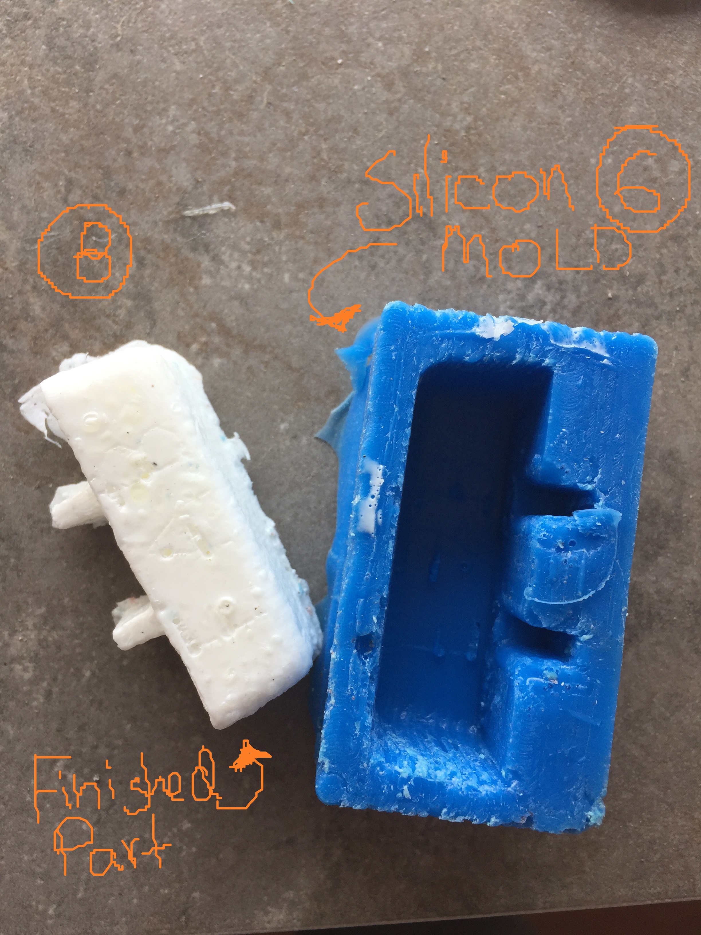
The machined mold final part on the left. The casted mold part on the right.
.JPG)
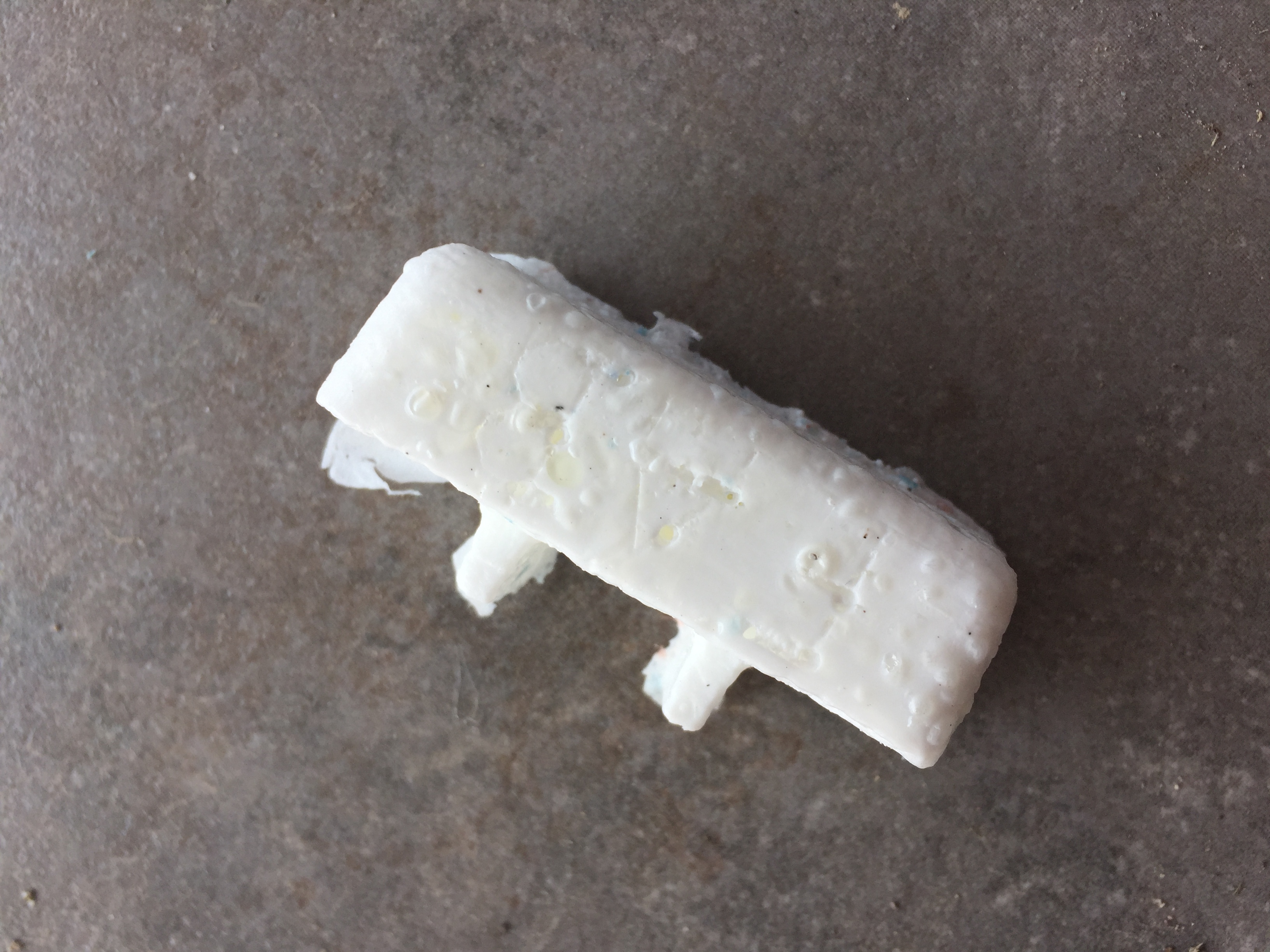
Here we see the final part and a test piece in order to see the development, as to damage the test part to see if the mixture fully cured. Unfortunately I unpaciently removed the final part before the tiem was due, creating this unstable bump-like surface.
.JPG)
With the left over material, we also decided to protect some of the PCB's created in previous weeks. My pcb is on the left.
I aquried the practive to always lable at least the gnd pin in my circuits, as not to burn ever my pcb by accident.
Individual Assignment: Design a 3D mould around casting
Creating a chair-joint plug or cover
.jpg)
.jpg)
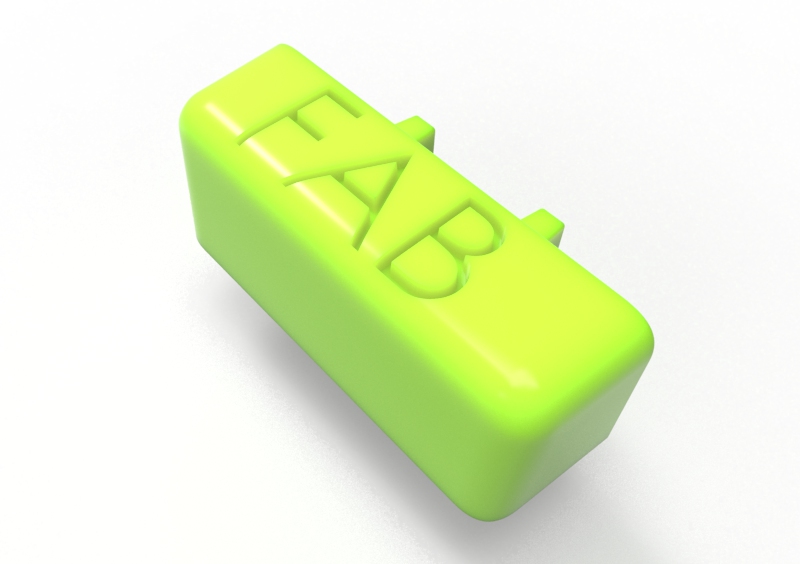
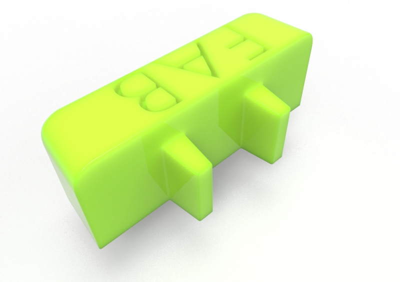
I require a simple yet usable mold and casting part. I developed a very simple cover for a join in the rocking chair done in week 8 - controlled cutting
In this case, I edited the multibody part done in the previous assignment and exported it into a new file. Inside I primed the file for casting. Adding mostly 5deg draft and Raduis curves. Aditionally I added a text 'FAB' to add a bit more complexity.
My instructor @Gallo guided me into creating a single side mold and part usng and rearanging efficiently every feature in order to focure in the actual produciton of the week. Im hopping to get a slick finished cover.
The design:
.JPG)
Here are the design notes and modifications done.
.jpg)
This is the final part.
.jpg)
In between I also decided to test a sample in 3D print cause .. the printer was next to me.
.JPG)
So solidworks had draft feature: looked too good to be true. It was. It actually added about 2mm per side.. so the final part was not close to fitting in its holes. The full joint hole was 6mm and the final part was 8+ mm. I enede reding and printing the test. Good thing I Tested it out in the 3D Print.
.jpg)
To fix it I used the 'draft' feature option inside the extrude feature.
Once the cad was fixed, it became time for the pre-machining. In this case I used jewler's wax.
The modling casting plan:
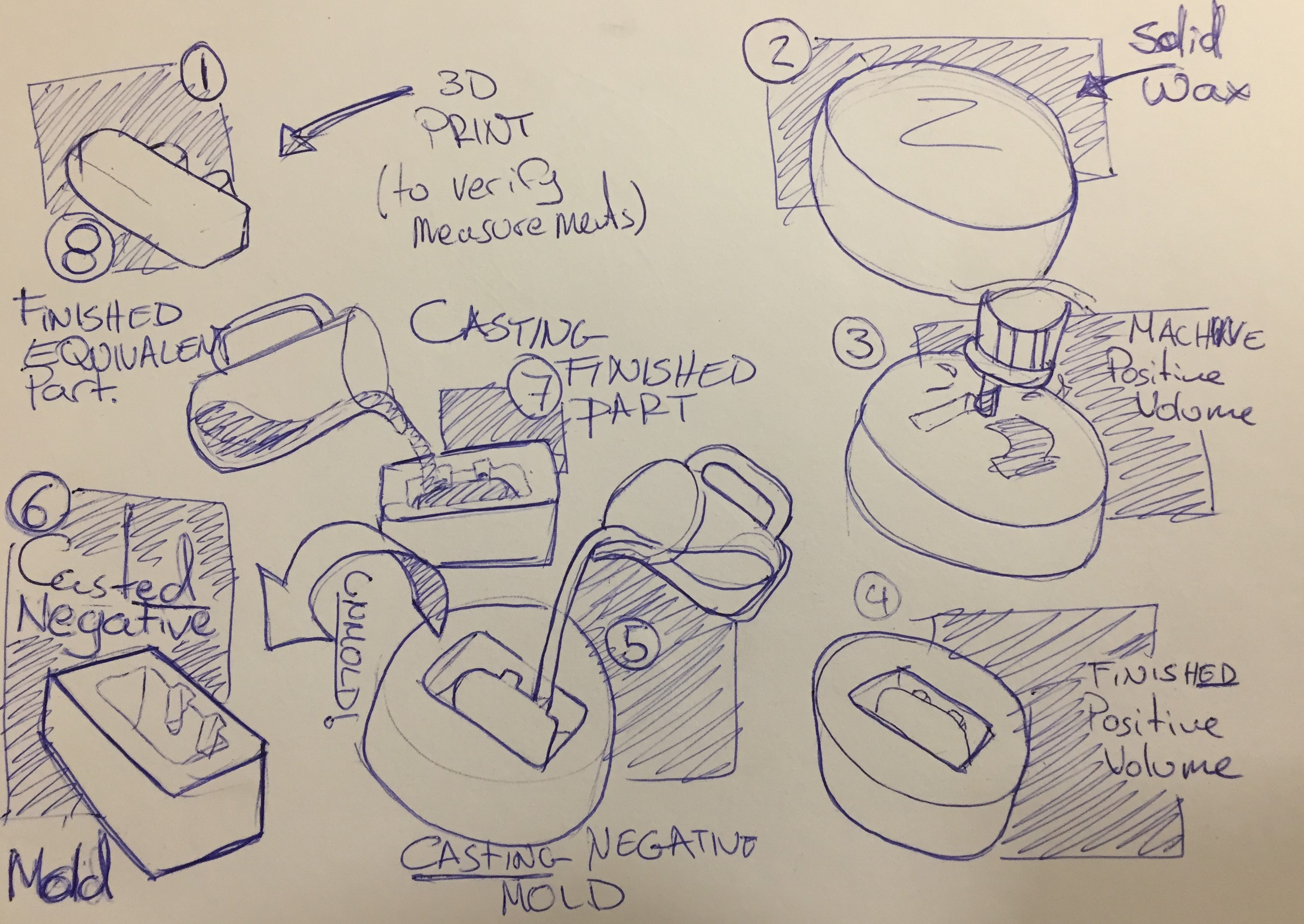
| 1. 3D print (to verify measurements) | Printed in Pla |
|---|---|
| 2. Solid Mold of Wax | |
| 3. Machining positive volume | Using the Lab's CNC, with a 4mm flat head milling bit. |
| 4. Finished Positive Volume | |
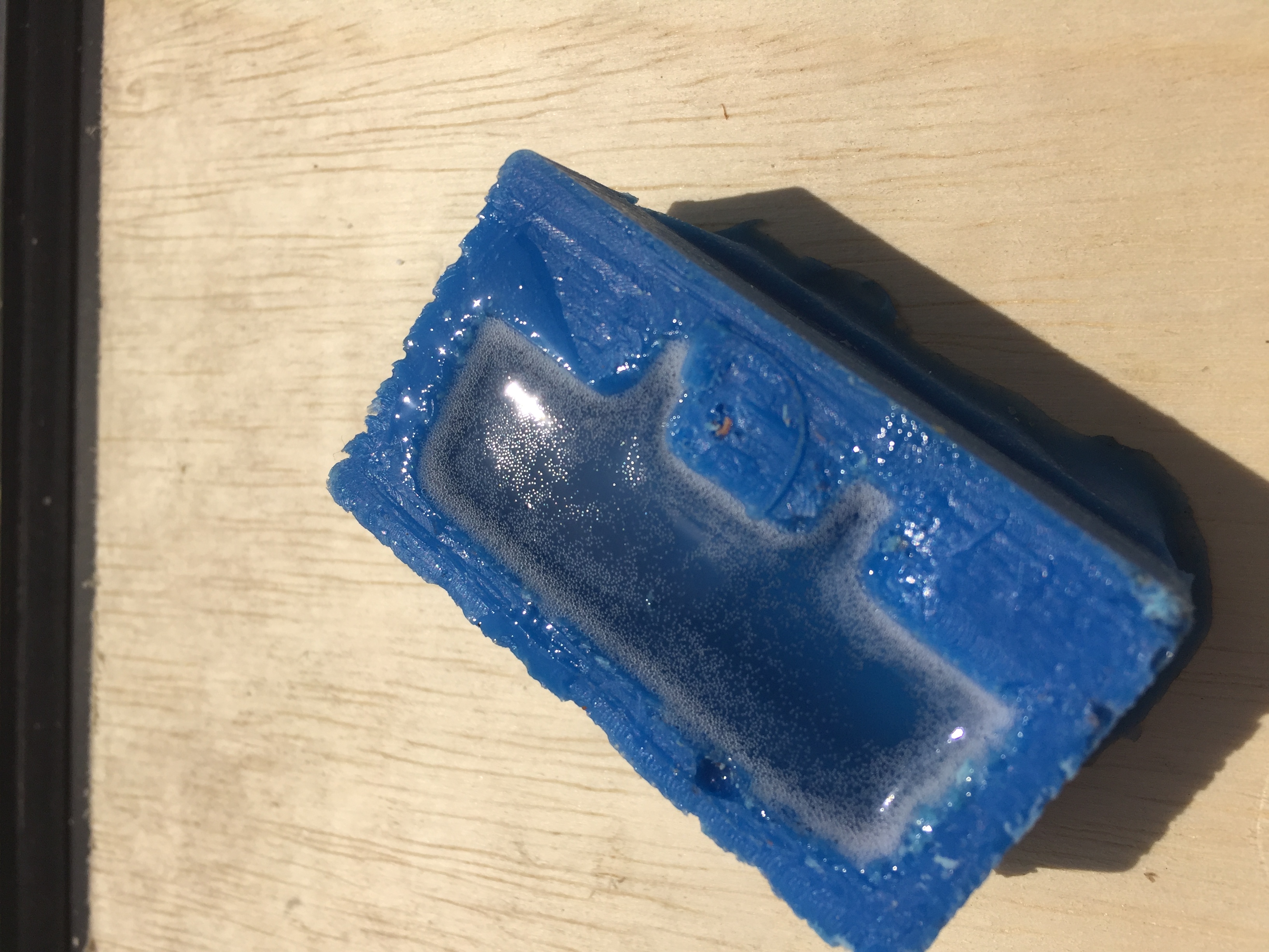
| 5. Casting the Negative Mold | I Used Mold Star 30, a silicon based 2 compoent plastic, used to take the nevative volume. |
| 6. Casted (finished) Negative Mold | The silicon also makes unmolding much easier, it mantials an easy unmolding property as result of its flexibility. |
| 7. Casting Finished Part | The final part was created with Smooth-Cast 61D, a two part epoxy resin that has great mechanical properties |
| 8. Casted (Final) part created |
2. Solid Mold of wax
I used a wax ment for jewllery that holds its shape well. Its sturdy and typically used for the lost wax process. In this case I will be pouring silicon and later solid plastic.
Typically its melted down, and carved. In this case the carving hand will be the CNC machine.
A heat gun sufices to melt the material, and using a properly sized tupper-ware the process for the raw material is complete.
An important distinction was the operation of roughing, as it is ment to take out tons of material, fast and its very low resolution. In this case it whent arround the part and uses a large stepover.
3. Machining the positive volume
I was so proud of actually creating this g code, I became a shame to see it all fail due to unproper programming.
4. Finished Machined Positive mold
5. Casting the Negative Mold & 7. Casting Finished Part
8. Finished part
To Conclude
This week was overwalming. It was however a great example of the capacity and variaty of materials we could use to create. Based on this process is possible work with almost any plastic or shape for prototyping purposes.
Reflexting back, I could have aquired more time with more pacience, as the melting wax took twice as long and the surface finish of the part also deteriorated if I had not taken it out of molde before the time is due.
I was not aware of the options offered in the Smooth-on family, aside the in-depth techinal specification take a lot of the guess work I have had to do working with other components.
We all casted the parts as a group We did have each our own part machined, we shared the materials in order to optimize resources & help each other out. Otherwise Doing each by its self becomes harder.