
Project developement
Input device, one of the assignements for the final project, this is the moment to start it !
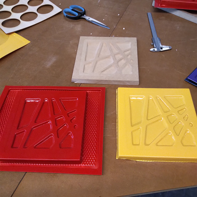
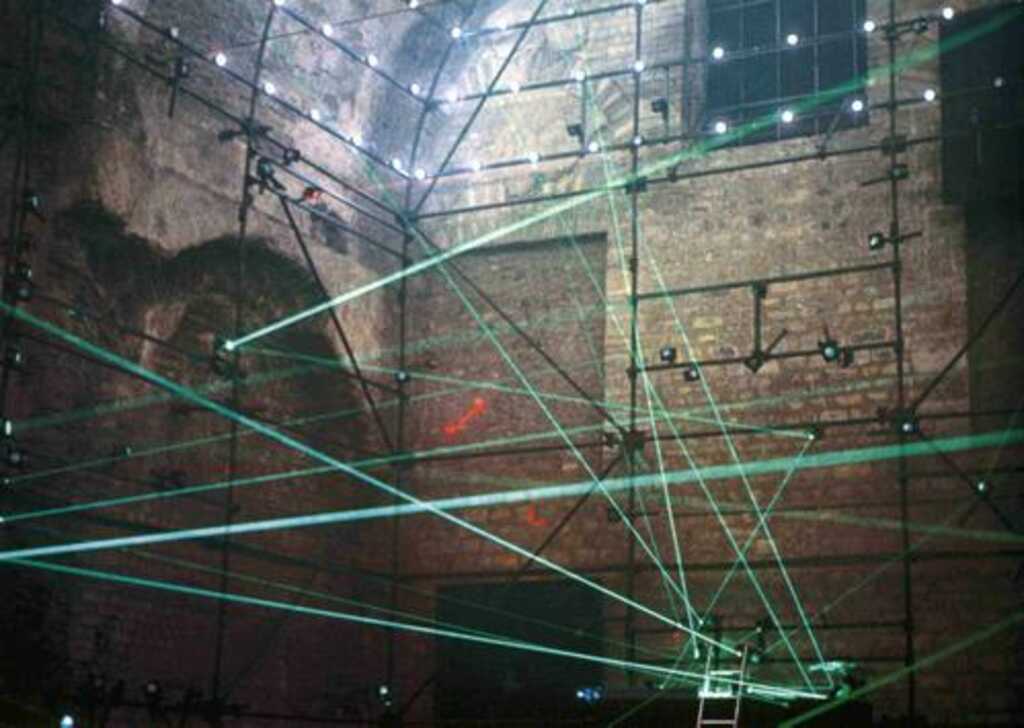
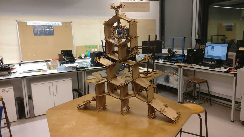
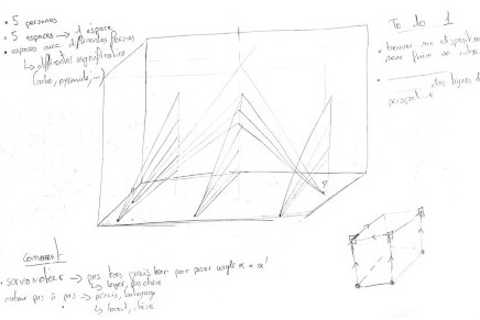
My idea of my final project is to create a dynamic and modular scenography using lasers, servo motors, galvanomotors and mirrors ! What kind of input can I have on it ?! After taking the time to think, in a first time I want to be able to control parts of this scenography with a joystick.
Let's try to make a little prototype !
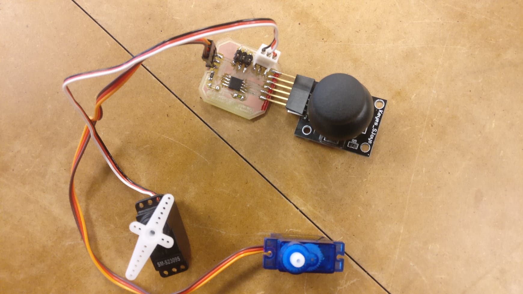
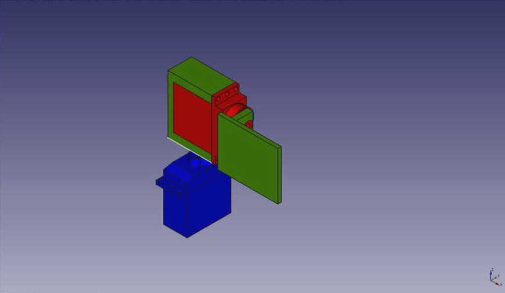
In order to test the concept I will use an arduino uno, a 2 axes joystick and 2 servo motors.
The concept is really simple. In order to read the values from the joystick I will connect the X and Y pins of the joystick into two analog read of the arduino. Afterwards, I connect the two servo motors into the pin 5 and 6 !
In order to prototype it easly I used a breadboard... In order to avoid some voltage drop when I use the servo motor I have added some capacitor of 100 uF beetwen the GND and the VCC of my servo motors and my joystick. I have also used an external power supply
And this the result !
This method is really simple and the result are very good ! I think I will put my mirrors on a similar system in order to control them !
But this week I need to make a PCB ! And who said joystick mean also a controler !
Okay then the idea here is to make a wireless joystick using an esp wroom 32, What I want in my board :
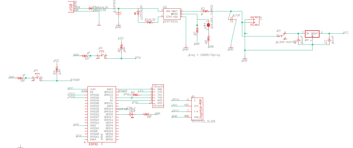
My first step is to design the battery charger !
To do this I inspired me with a Sparkfun battery babysitter and with a document that I found on forum. minimal circuit for esp wroom 32
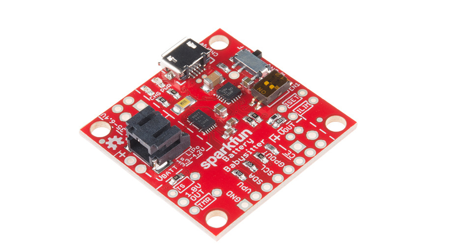
Basically, there is two "special component" for this part of the board :
And here in the top part you can see the schematics !
Now let's make the esp32 part !
First step : read the Data sheet In the stapping pin section we can read that we need two buttons in order to put the esp on the boot mode. One a dev board this two buttons match with the boot button and the EN/reset button !
And finally the last step is to connect the joystick and a led.The joystick is available in the switches eagle library of sparkfun ! The joystick must be connected on the analog pin of the esp !
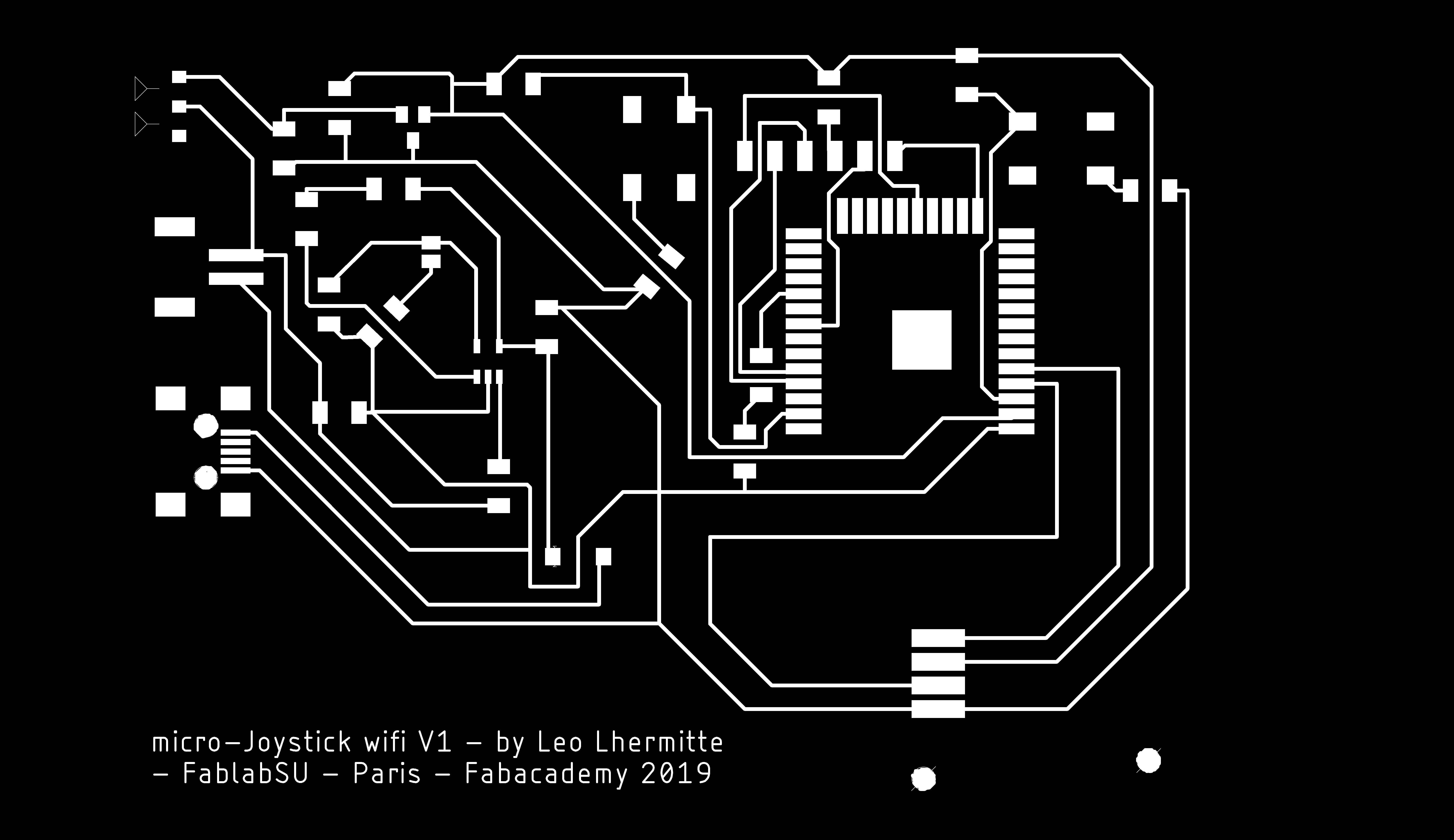
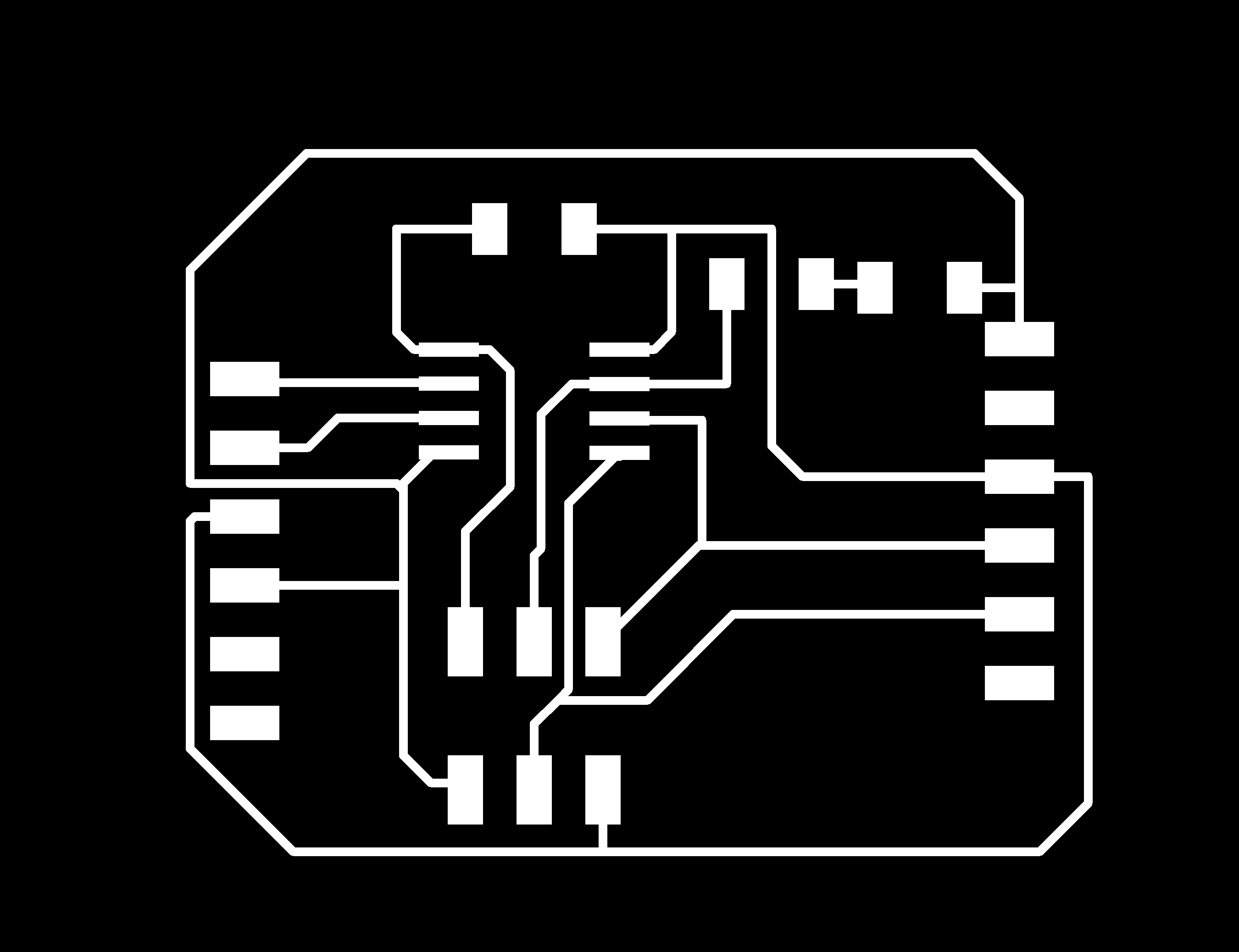
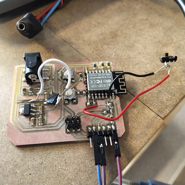
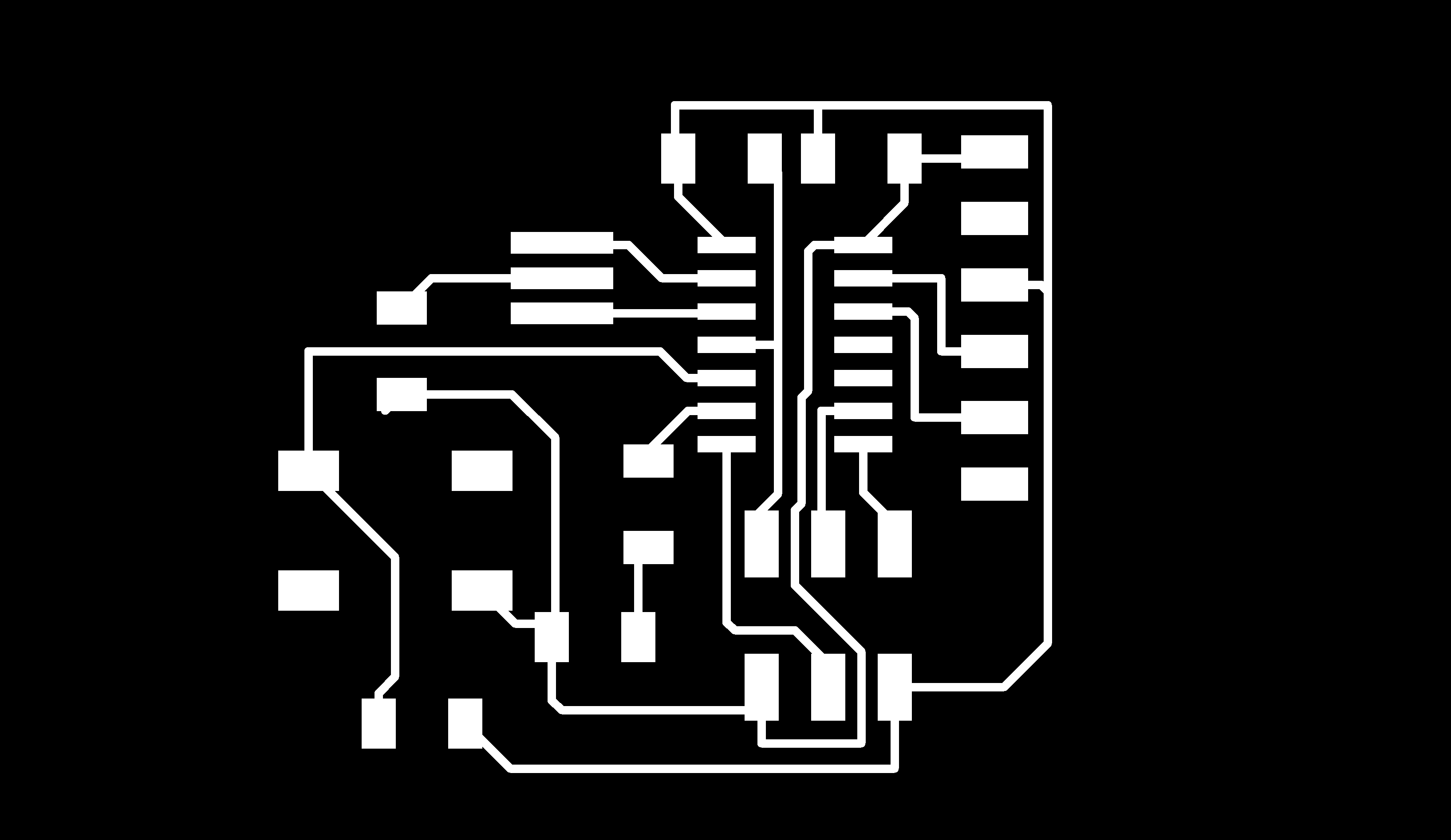
And finally this is the board view ! This is pretty funny because, route all the board was for me some painful moment. And with this board I realised that this part could be also fun ! I don't know exactly why, maybe because that was my first big board or maybe because I'm starting to understand a little bit better how work this fabulous world of electronic !
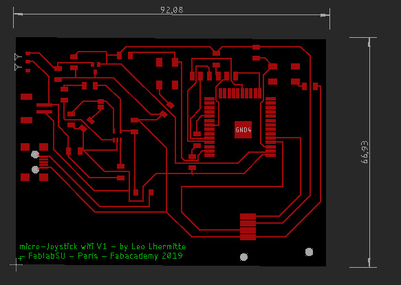
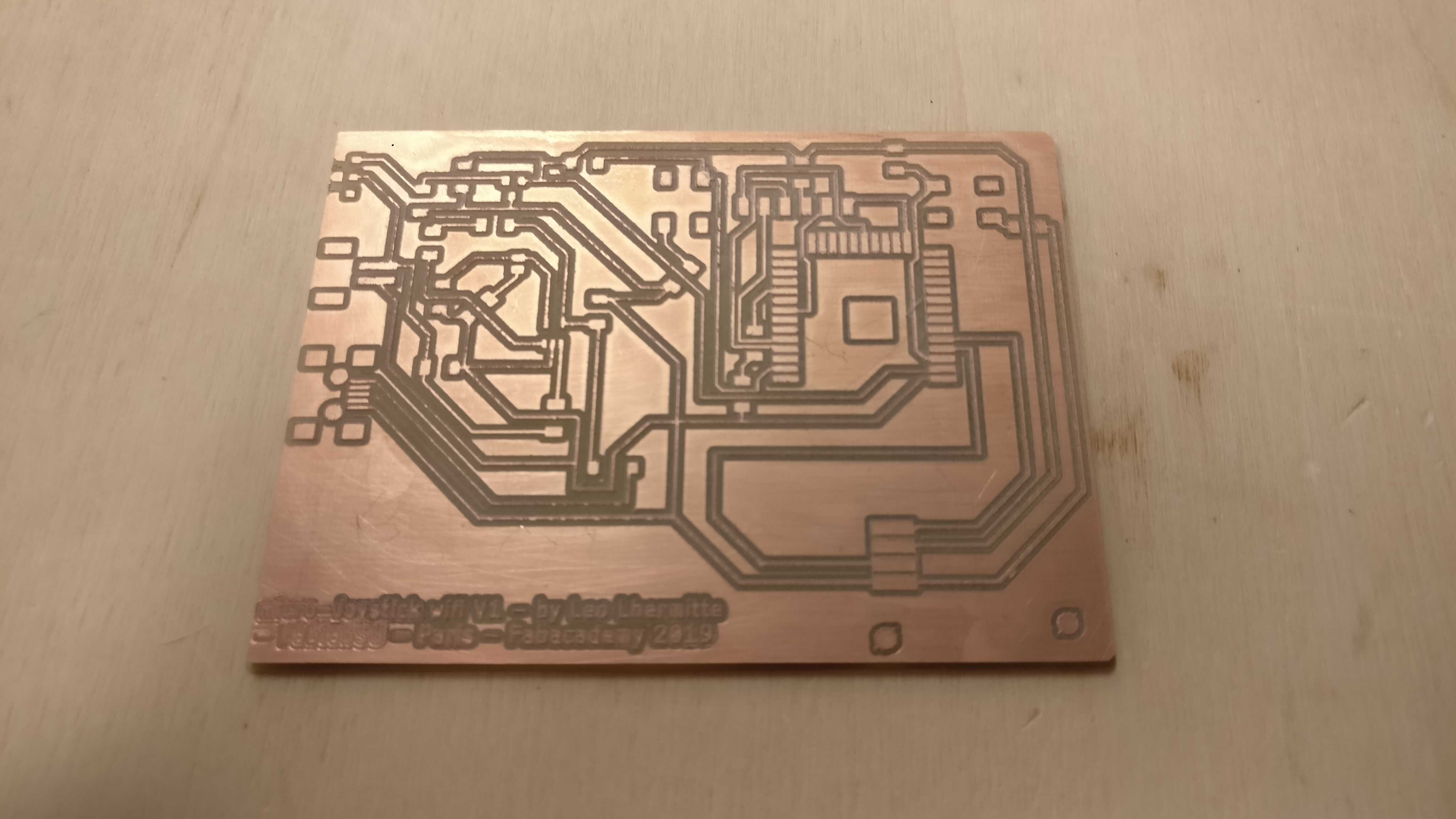
If you are interested of the detail of this part go to my Electronic production week In order to machine this PCB I used a V bits of of 10° angle and a depht of 0.04mm.
Unfortunately my PCB was not perfectly flat... Then I have re-made my Z zero behind the PCB 0.05mm under the old Z zero until a uniform good result is achieved.
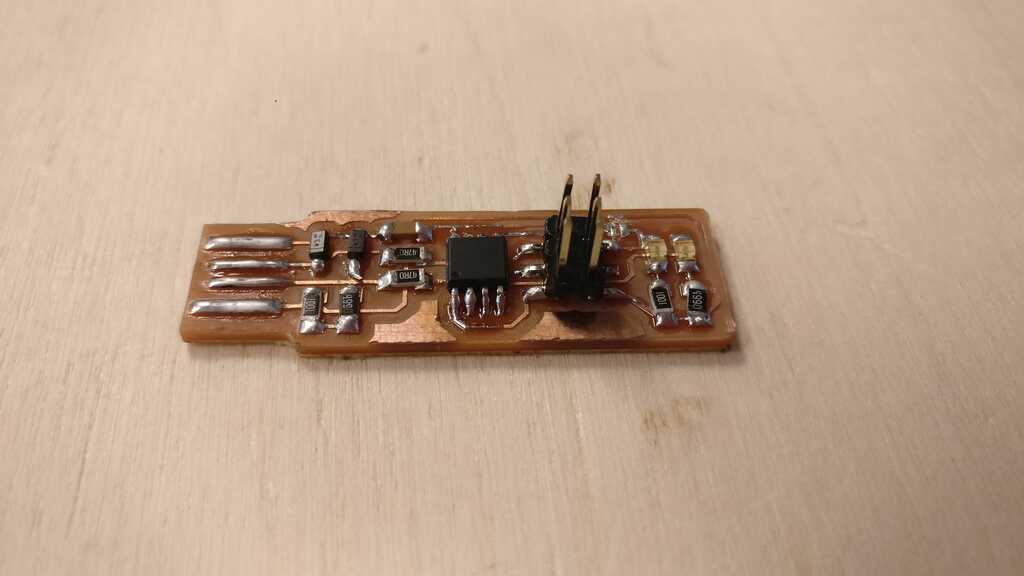
Now I have to sold all of the components :
I love this part of the fabrication process because this is the moment to use my hand, the theorical part is finish ! But sold an esp32 is not an easy part ! There is 38 pin of 0.9mm and I used all my concentration to get to the end without doing anything stupid.
Little tips, in a first time I put some tin solder on the pin of the esp32 and after I put the iron on the trace very close to the pin and I connect the Iron and pin with some tin solder.
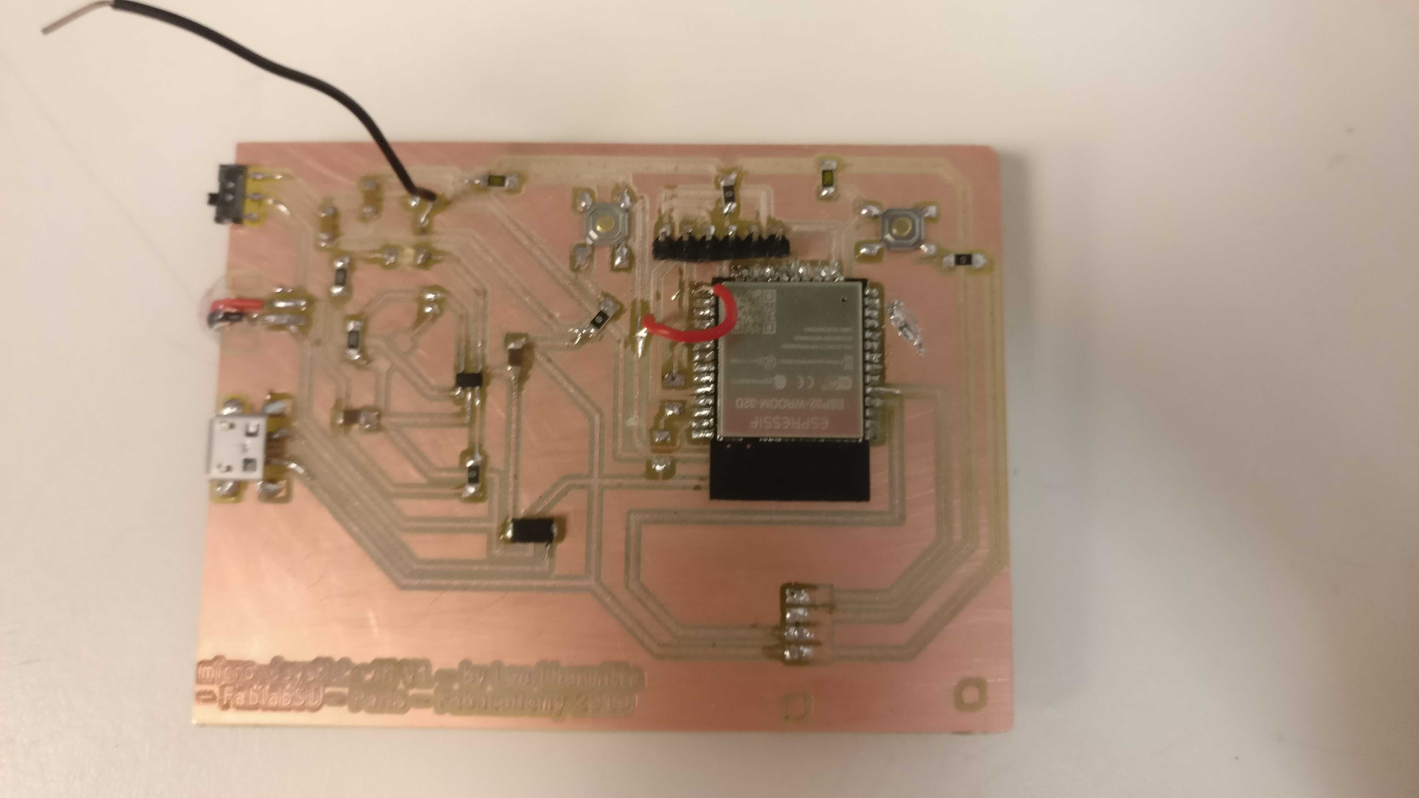
Sorry for the picture my smartphone is having trouble to make the focus...
I don't know why but impossible to receive any signal from the esp32. I have checked all of my solder and connection, checked if the buttons worked well and if the esp was properly powered...

In order to understand the problem I think that I will try to get the eagle file of dev kit board like an nodemcu 32 based on esp32. And compare my board to there board.
Basically, I have started to design this board without readed enough documentation.
After the end of the week I have made some searches about the minimal circuit in order to exploit the esp-wroom-32. Hardware Design Guideline .
In this guideline the first part is about the power supply : ESP32 uses a 3.3 V system power supply. The chip should be activated after the power rails have stabilized. This is achieved by delaying the activation of CHIP_PU (Pin9) after the 3.3 V rails have been brought up. This mean that here I have made a first mistake because there is only one power supply pin connected on my schematic.
Then we know more about the reset pin : CHIP_PU serves as the reset pin of ESP32. The input level for resetting the chip should be low enough and remain so for a period of time. To avoid reboots caused by external interferences, the CHIP_PU trace should be as short as possible and routed away from the clock lines. A pull-up resistor and a ground capacitor are highly recommended. CHIP_PU pin must not be left floating. Here I don't see any mistake from my design.
Finally, I think that my mistake is about the power supply... I will after the fabacademy re tried some experimentation with the esp32.
Okay It's 7pm and nothing work. Tomorow I need to have something. I decided then to make board using an attiny85.
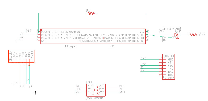
Basically, The first thing is to connect the VCC and the reset pin through a 10K Ohm resistor. This allow to switch on the attiny (If the reset pin is low the attiny is off).
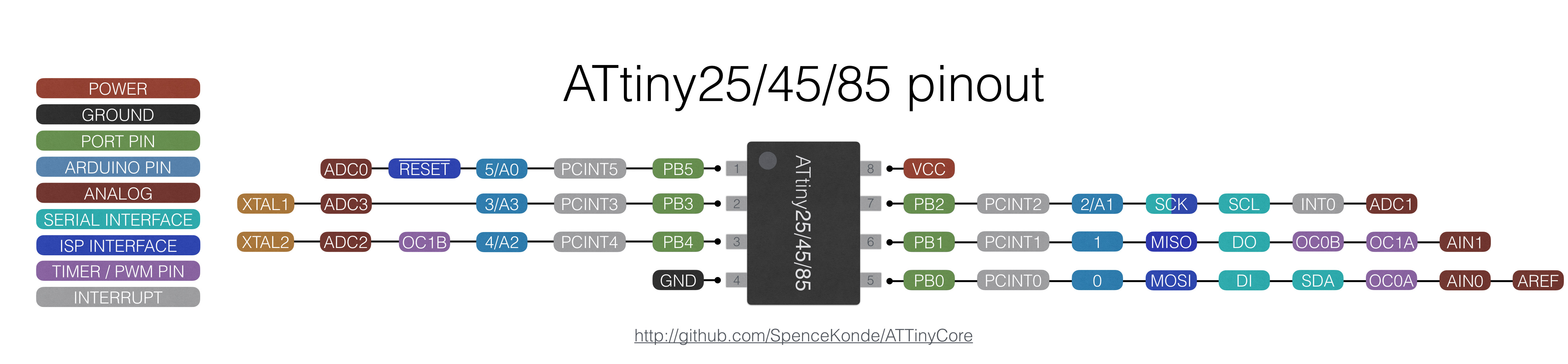
Then the ATTINY is ready to work. Now we can connect the joystick into the analog in of the ATtiny (A3 and A2). In order to know what is each pin let's make rapid google search : "attiny 85 pinout". Be careful, the signal from the joystick is an analogic signal (basiccaly, the joystick is just two potentiometer) then every pin of your micro controller can not read this type of values.
Now we need to be able to program the attinttschematic.jpegattiny. In first time the attiny need to be flashed. Then in order to flash it I have added a ISP connector. It is connected to the MISO, MOSI, SCK, RESET, VCC and ground pins of the tiny in order to program it. I will use he fab isp made in the electronic production week.
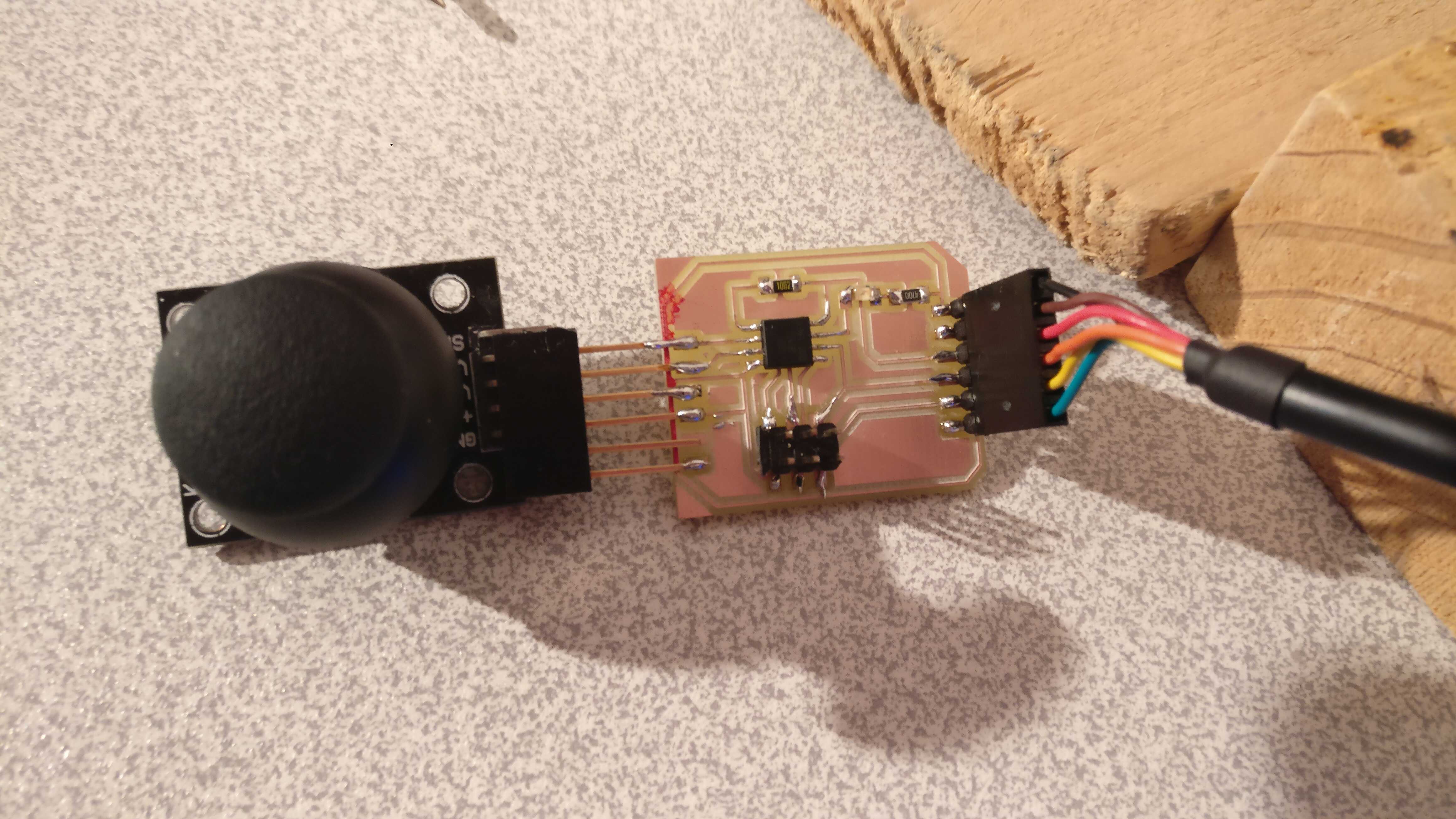
And finally I have put an FTDI connector to have a serial connection to my computer, in order to see the coordonates of the joystick. The FTDI connector need to have at least 4 pins connected. TX and RX, through them the data will be transfered. The GND in order to have a commun 0 V (low reference for the data signal). And the VCC if you want to power the board through the ATTINY, especially when you use the fab ISP, you need a additinal power supply (the fab ISP doesn't provide enough power supply).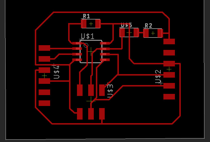
Now let's program it with this little code :
#include
#include

#define pinAxisX A2
#define pinAxisY A3


int x, y;

SoftwareSerial mySerial(0, 1);

void setup() {
  Serial.begin(9600);
  Serial.println("\nStarting joysticko");

}

void loop() {
  x = analogRead(pinAxisX);
  y = analogRead(pinAxisY);

  x = map(x, 0, 1023, 0, 180);
  y = map(y, 0, 1023, 0, 180);


  Serial.print("x: "); Serial.print(x);
  Serial.print(" y: "); Serial.print(y);
  Serial.print("\n");

}
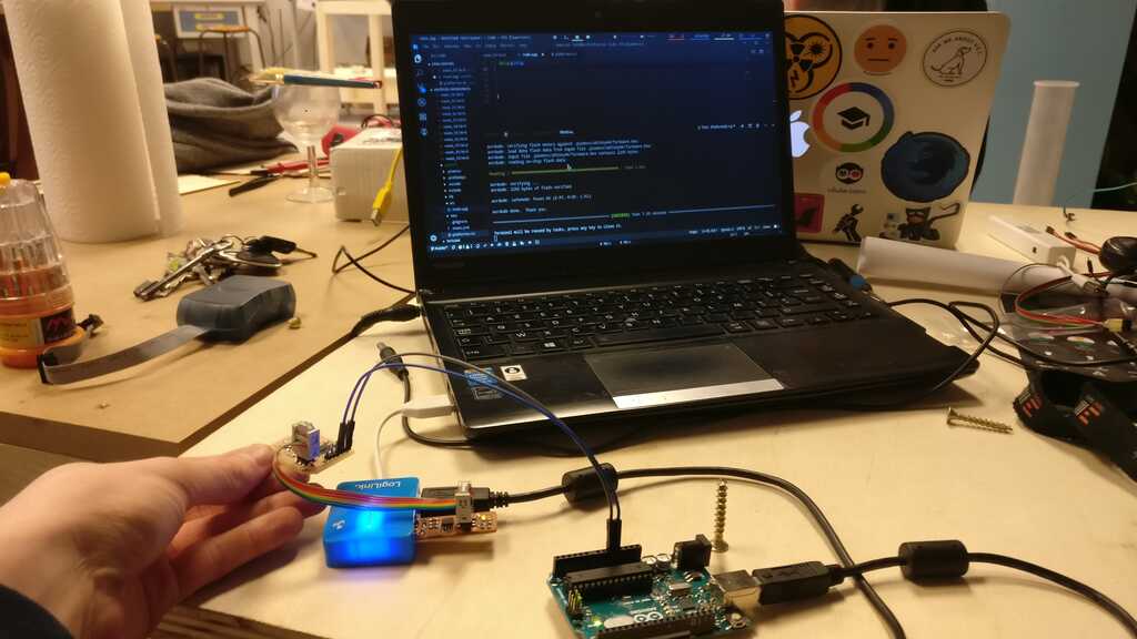
In order to programm it I have followed the same method and the same fab ISP of the Week 9 - Embedded programming
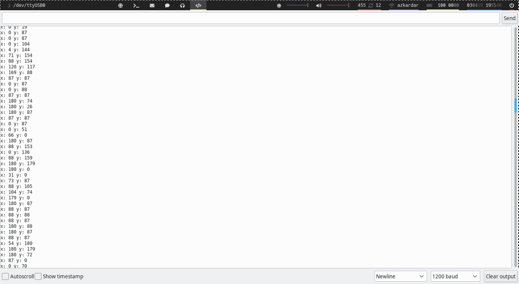
Now let's try to read the values from the joystick.In order to read the value send from the attiny I use the serial monitor of the arduino IDE.
This week was for me really exciting ! I immersed myself in something that was very new to me and that was not so easy. I really liked to discorver and to try to understand what was the minimal circuit in order to create esp32 based board ! I think I'm almost there, and I just need few more try with a new look at what I'm trying to do. I think my problem is coming from the power supply of the esp.
joystick + servo .Ino file eagle shematic of the battery-sitter eagle board of the battery-sitter eagle shematic of the microJoystick wifi eagle board of the microJoystick wifi png traces of the microJoystick png outline of the microJoystick eagle shematic of the ATtiny joystick eagle board of the ATtiny joystick png traces of the ATtiny board png outline of the ATtiny board read joystick value cpp file
Project developement
Intelectual property
Wildcard Week
Machine design
Interface

Mechanical Design
Networking and communications
Application and Implication
Output device
Input device
Molding and casting
Embedded programming
Computer-Controlled Machining
Electronics design
3D scanning and printing
Electronic production
Computer controlled cutting
Computer-aided design

Versioning and Website
Idea of my final project
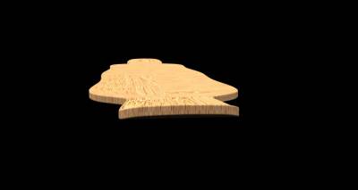
How to modelise a longboard
For any suggestion, help or featured project