

Project developement

In the previous section of my final project documentation I talked about the first tests using different technology. In this part I will mor talk about the last part of my final project. Basically, the idea of my final project is to create a dynamic scenography system using lasers. I have tested some things usings galvanomotors but the result was not very good. Finaly, I chose to create some boxes (mini projectors) that are controlling a laser using servo-motors.
In this section of my documentation I will explain the different step of how I created my final project. Some parts of it have been made during some thematic weeks, in this case the link to the technical detail will be put.
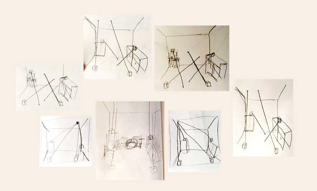
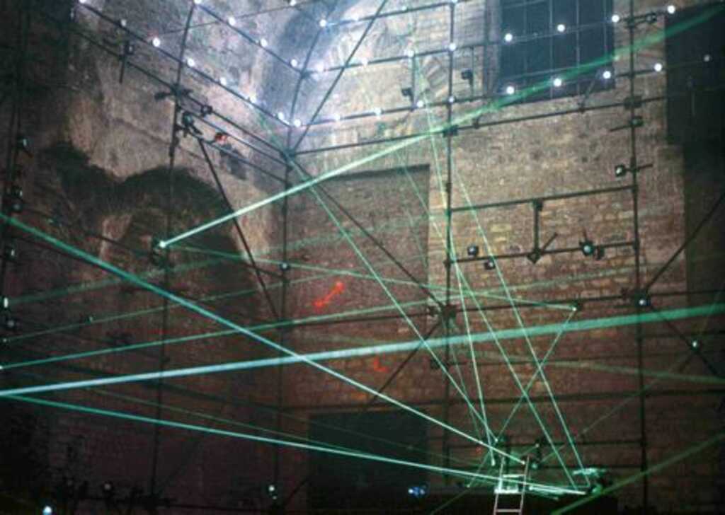
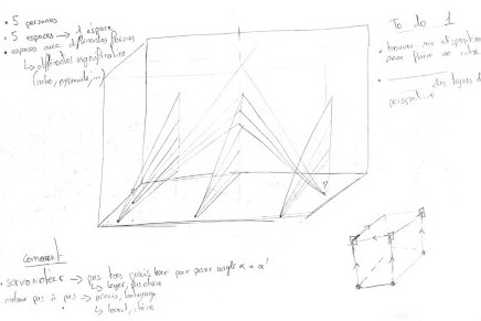
In a first time I want to talk about what is the idea and how the idead has come in my head. Before anything, I need to explain that a big part of my life orbit around the music and event field. I play in different bands and I'm also a technical manager for events. The very first time when I get the idea of playing with lasers I was in a french techno party in an abandoned place, the organisation and the materials was incredible for an unauthorized event. There was some big led screens, a lot of motorized led projectors, a lot of lasers projectors. The show was really great and with a very noticeable link and complementarity beetwen visual show and audio show. But at one point, I thought about the fact that this all material was so expensive and so complicated to transport... Then in my head I have played a little game of how I could have organized a party of this magnitude without so much money. Then I started to think about a scnography system using lasers and mirrors. The idea was to have some little modules of lasers and mirrors, and the purpose was to create a show by playing with the reflect, the movement and the placement of the mirrors.
Finaly, because of time and complexity I choose to only play with lasers !
For the technology, there is a lot of kind that I could use but in order to get the most suited, I need to lay the groundwork for the project. At this moment, I want for my final project :
 Then about the galvanomotors. The good point is the speed of movement, in fact using them I could be able to have enough speed to play with retinal persistence and then to create surfaces.
But there is a lot of difficulty using galvanomotors. The first one is the price, you can get back some of them into old electronic devices, but in most of the case they are not adapted to move quicly and then they are very unstable.
If you buy one of them, there is finaly a lot of electronic problems. This kind of motors are some analogic devices and you need to convert a digital signal (0V to 3V or 5V) into a analogic signal beetwen -10V and +10V and that's not so easy.
Then there is the problem of the weight. They are very unstable to such an extent that a fresh gale will move them and it's totally impossible to put lasers on it, the only solution is to put a mirror that will move but this is really tricky.
Then about the galvanomotors. The good point is the speed of movement, in fact using them I could be able to have enough speed to play with retinal persistence and then to create surfaces.
But there is a lot of difficulty using galvanomotors. The first one is the price, you can get back some of them into old electronic devices, but in most of the case they are not adapted to move quicly and then they are very unstable.
If you buy one of them, there is finaly a lot of electronic problems. This kind of motors are some analogic devices and you need to convert a digital signal (0V to 3V or 5V) into a analogic signal beetwen -10V and +10V and that's not so easy.
Then there is the problem of the weight. They are very unstable to such an extent that a fresh gale will move them and it's totally impossible to put lasers on it, the only solution is to put a mirror that will move but this is really tricky.
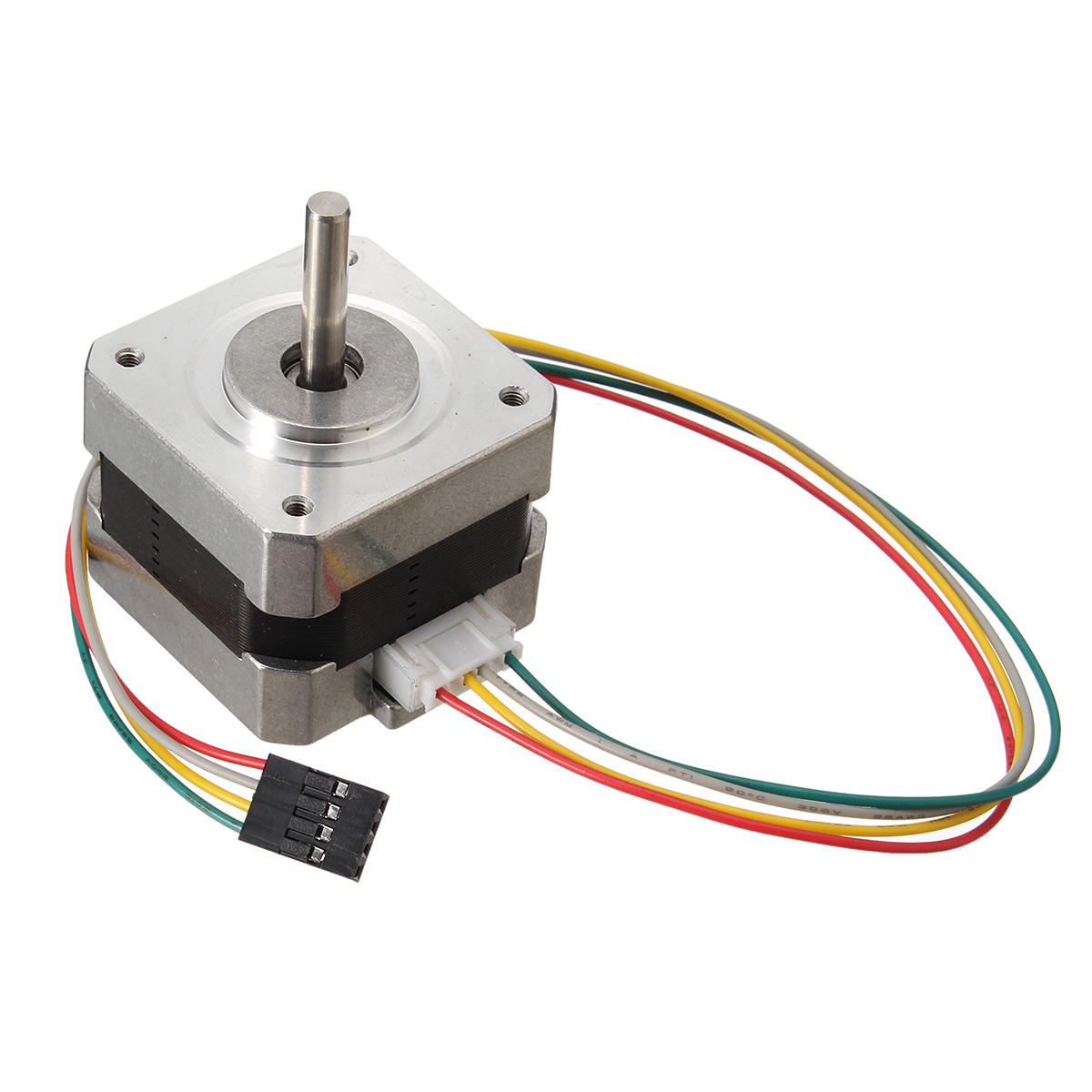
 Finaly, I chose to use servo motor for different reason. The first one is the price, they are really not expensive and then I can make a lot of test. Then they are really easy to control. They can carry a little weight (laser for exemple) and they are not to big !
This is perfect for what I want to do ! But there is also some problems. The first is the quality and the reliability of those low cost servo motors. Then there is also another constraint about the rotation, most of the servo motor are only rotating around 180 degrees.
Also there is the fluidity of the movement, we feel a lot the steps during the movement. But this is not a big problem for a V1.
Finaly, I chose to use servo motor for different reason. The first one is the price, they are really not expensive and then I can make a lot of test. Then they are really easy to control. They can carry a little weight (laser for exemple) and they are not to big !
This is perfect for what I want to do ! But there is also some problems. The first is the quality and the reliability of those low cost servo motors. Then there is also another constraint about the rotation, most of the servo motor are only rotating around 180 degrees.
Also there is the fluidity of the movement, we feel a lot the steps during the movement. But this is not a big problem for a V1.
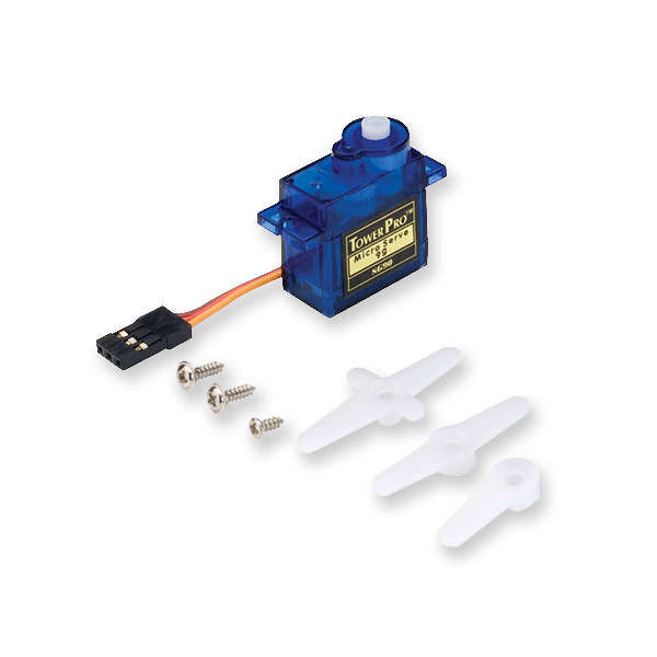 Then after some searches I choose to take the most low cost servo motor that I could. The basic SG-90 !.
Now, I need to choose wich material and technology I will use in order to create the case. The constraints that I have are to be easy to prototypate it, strong enough in order to support the weight of the servos and the laser. After a little brainstorming this is the differents ideas about the how to make the case :
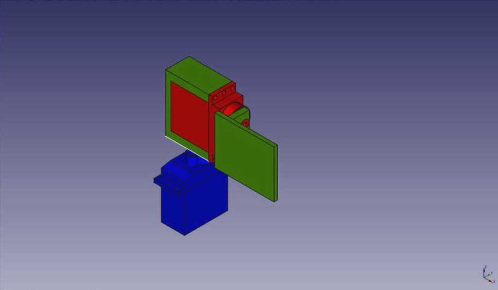
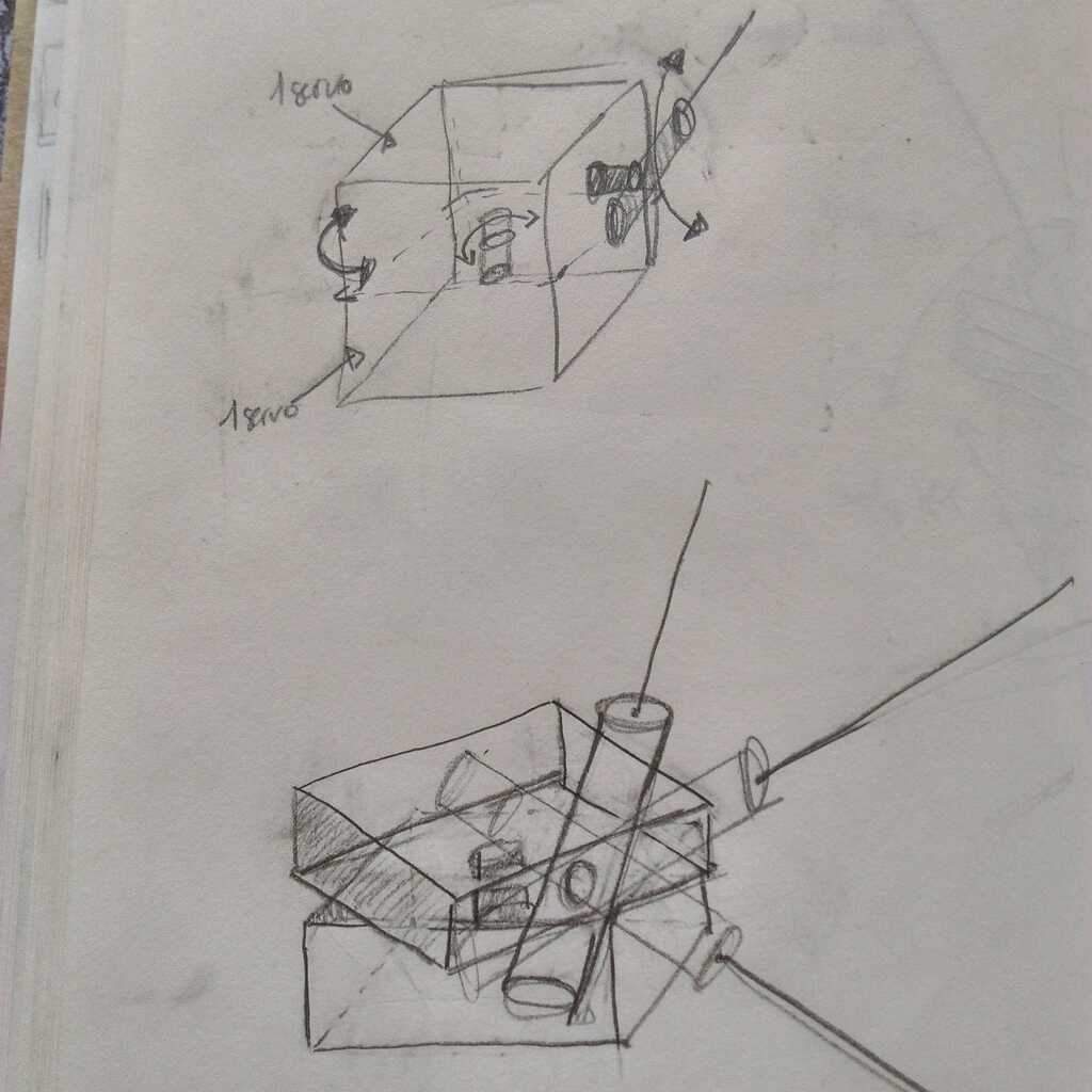 Now I know what kind of technology I will use then I am able to know how I will design the case. Basically, I want to have this idea of little boxes that could be placed where you want.
The box will be composed by 3 compartment. The bottom compartment will contain the electronic card. The middle one will contain the first servo motor and above it the top compartment will contain the second servo.
Now I know what kind of technology I will use then I am able to know how I will design the case. Basically, I want to have this idea of little boxes that could be placed where you want.
The box will be composed by 3 compartment. The bottom compartment will contain the electronic card. The middle one will contain the first servo motor and above it the top compartment will contain the second servo.
I will use Rhino in order to modelise it because I'm more comfortable with it and in case of problem with another software I risk to lost of lot of time...
Let's see how I have designed the boxes !
In a first time I found a 3D model of the SG-90 on the web, fortunatly that was not a .STL but a .STEP. The advantage with this extension is that it is a lot more modular and you easly de break down the model into different part.
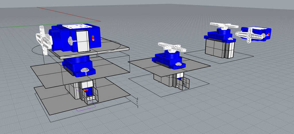 From the 3D model of the servo motor I have created the internal part of the boxes and the differents compartments.
Here the idea is to create something the more modular possible and easy to modify. I don't want to work on a really great design for now because I considere that I need to better integrate the sens of this creation in order to create a fine design that according well with the concept of the laserbox.
From the 3D model of the servo motor I have created the internal part of the boxes and the differents compartments.
Here the idea is to create something the more modular possible and easy to modify. I don't want to work on a really great design for now because I considere that I need to better integrate the sens of this creation in order to create a fine design that according well with the concept of the laserbox.
The compartment will be put on the first servo, but the problematic is that the moving part of the servo that will support most of the forces is only a little plastic axe. Then I choose to use the support sell with the servos.
Then the piece that will carry the second motor have under it a hole where the support of the first motor will fit.
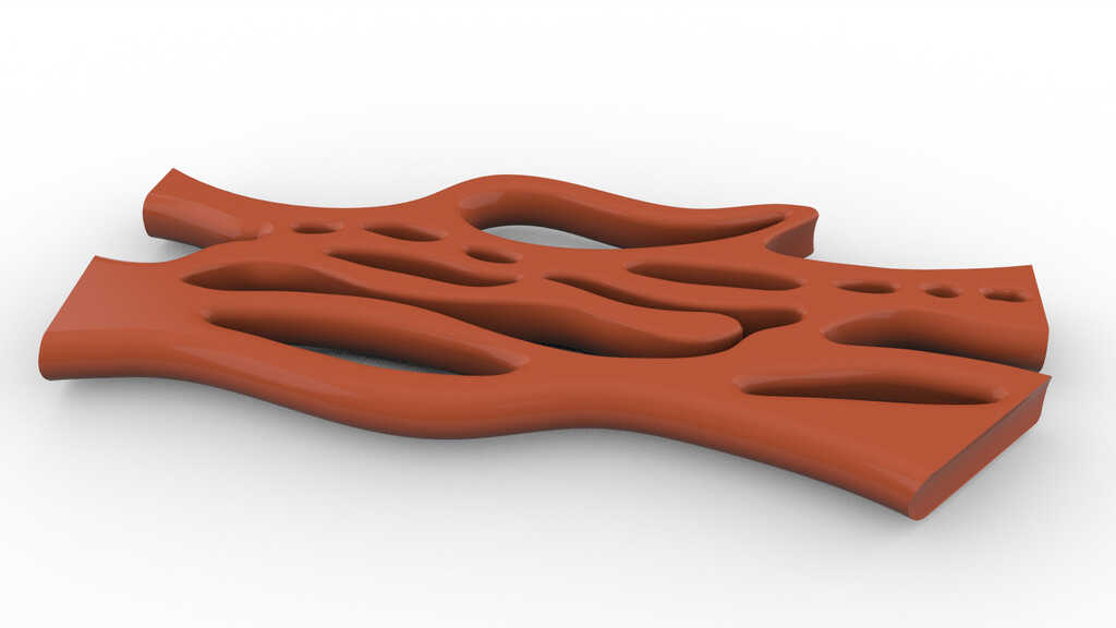
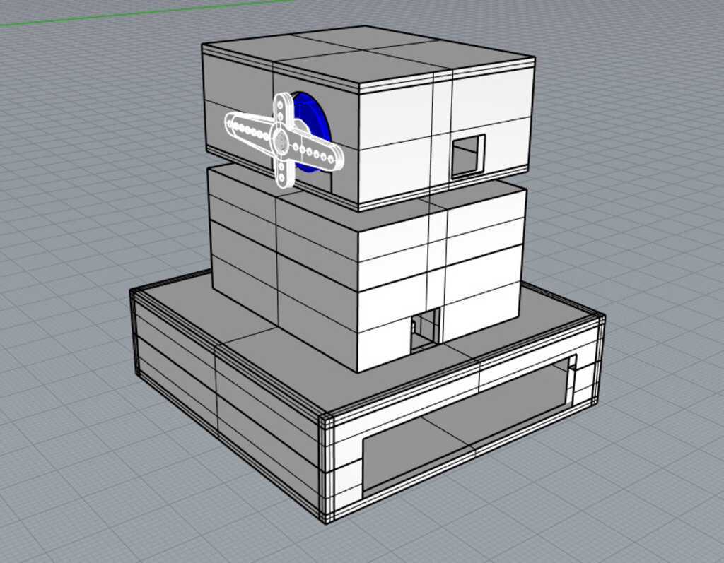 Finaly, this is the result after adding the surfaces around the box. I have also added some holes for the cable managment.
The idea with this design is to have the possibiliy to change it without changing all of the pieces. For exemple, if you want to add a battery compartment,
you just have to design another compartment that will be place under the electronic compartment. Also if you want to change the model of the motor you can just redisgn the motors compartment.
Finaly, this is the result after adding the surfaces around the box. I have also added some holes for the cable managment.
The idea with this design is to have the possibiliy to change it without changing all of the pieces. For exemple, if you want to add a battery compartment,
you just have to design another compartment that will be place under the electronic compartment. Also if you want to change the model of the motor you can just redisgn the motors compartment.
Then I have 3D printed the different part using an ultimaker 3 with PLA. The model is composed by 6 piece that fit all together in order to create the LaserBox.
In order to slice to model for the 3D printing I used Cura. The time of printing is about 6 hours.
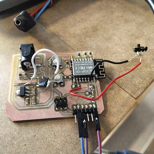
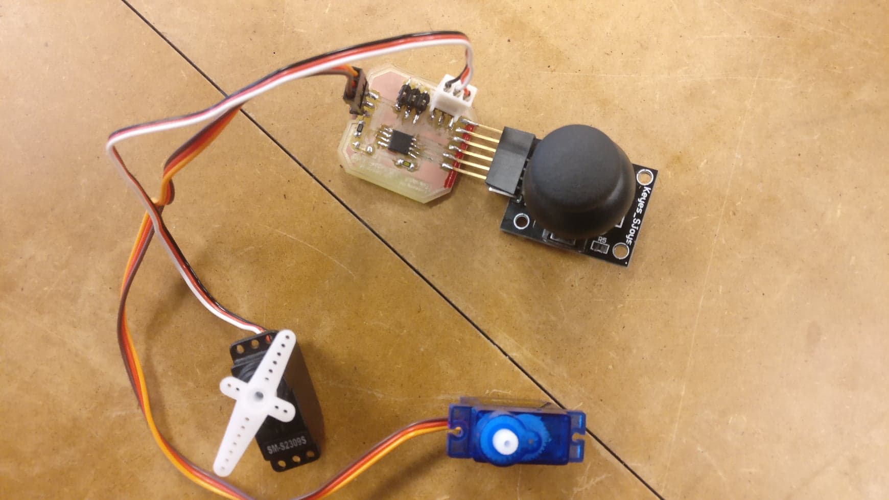
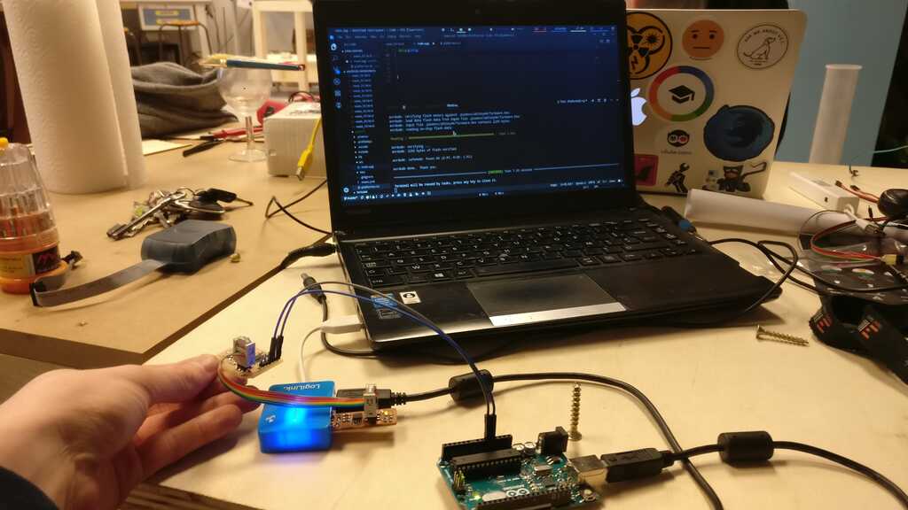
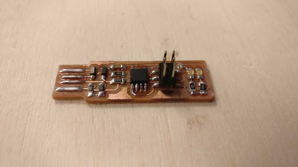
The next step is the electronic part ! For my board I used an ESP8266 because of the wifi compatibility. I will not explain in detail all of the electronic part. Most of the detailled is on my Output week.
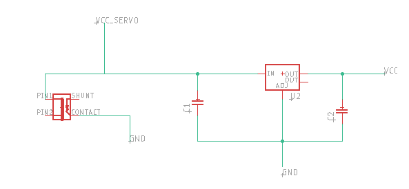
The ESP8266 is powered with 3V3 and my motor in 5V, then I decided to power the board with 5V and I added a voltage regulator.
The voltage regulator work with 2 capacitors C1 = 0,1uF and C2 = 10uF.
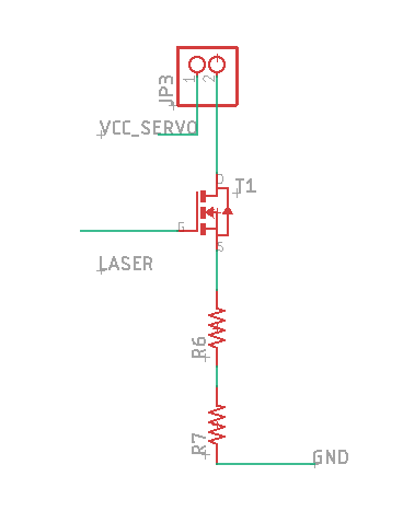
Now I will talk about how to control a laser (or something else) powered with a different voltage than the logical tension of you microcontroler.
In order to make this I use a NPN transistor, the connection of a NPN transistor is no trivial. The idea with a transistor is that there is a control pin that is activated by receuving a HIGH logical signal. And there is to other pin that will be connected or not in fuction of the control pin.
The Gate pin is connected to the ESP the Drain pin is connected to the GND of the device that you want to control and the Source pin is connected to the GND of the board.
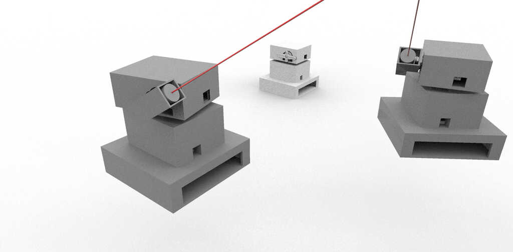
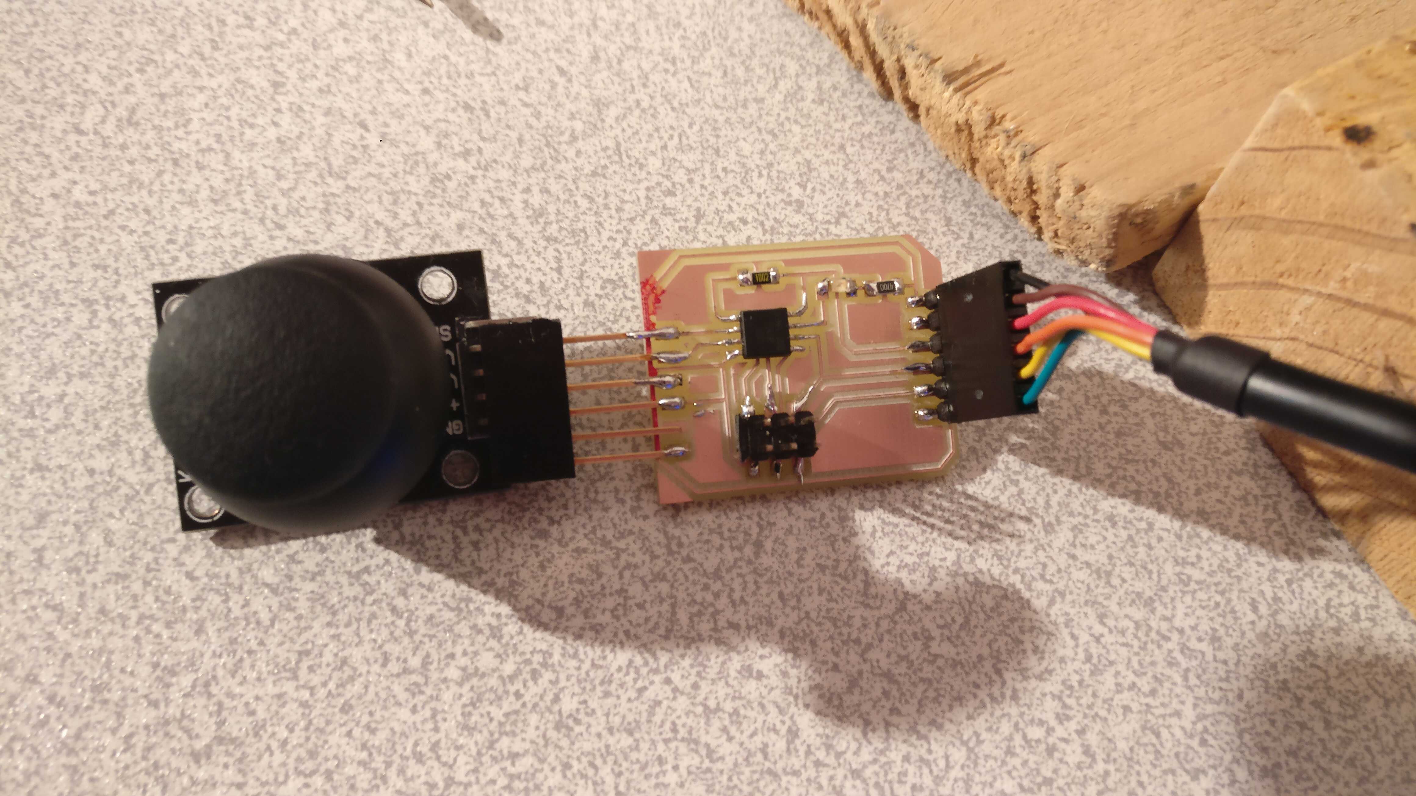
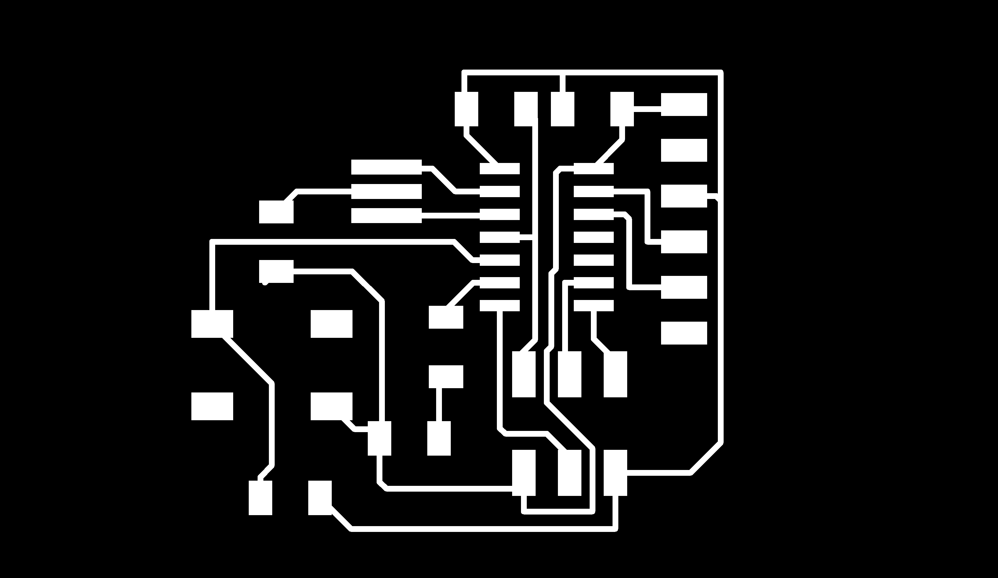
And finaly, this is the result after adding all of the part. In order to recapitulate this is the features of this electronic board :
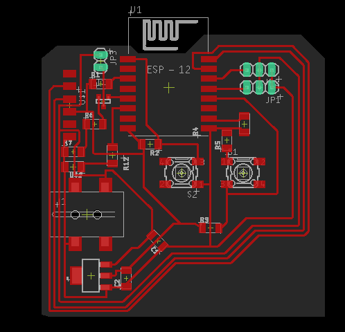 Finally I solded all of the component on the board.
////////////////////////////////////////////////////////////////////////////////////////////////
// transmission Web-Socket
///////////////////////////////////////////////////////////////////////////////////////////////

#include < ESP8266WiFi.h>
#include < WiFiClient.h>
#include < ESP8266WebServer.h>
#include < ESP8266mDNS.h>
#include < WiFiUdp.h>
#include < ArduinoOTA.h>
#include < WebSocketsServer.h> //pour la communication "instanée"
#include < Hash.h>
#include < Servo.h>

//////////////////////////////////////////////////////
// Initialisation transmission wifi
const char* ssid     = "";      //wifi name
const char* password = "";  //wifi password
const int portWeb = 80;
const int portSocket = 81;
const char* http_site = "/";

MDNSResponder mdns;
ESP8266WebServer server(portWeb);
WiFiClient client;
WebSocketsServer webSocket = WebSocketsServer(portSocket);

String webPage;
String etatLed="test";
boolean LEDStatus=false;
int ledPin = 13;
int servo1Pin = 4;
int servo2Pin = 5;
int laserPin = 14;

Servo servo1;
Servo servo2;


///////////////////////////////////////////////////////

///////////////////////////////////////////////////////
// TRAITEMENT SOCKET
///////////////////////////////////////////////////////
/*
typedef enum {
    WStype_ERROR,
    WStype_DISCONNECTED,
    WStype_CONNECTED,
    WStype_TEXT,
    WStype_BIN,
        WStype_FRAGMENT_TEXT_START,
        WStype_FRAGMENT_BIN_START,
        WStype_FRAGMENT,
        WStype_FRAGMENT_FIN,
} WStype_t;
 */
void webSocketEvent(uint8_t num, WStype_t type, uint8_t * payload, size_t length){
    Serial.printf("webSocketEvent(%d, %d, ...)\r\n", num, type);
    switch(type) {
        case WStype_DISCONNECTED:
            Serial.printf("[%u] Disconnected!\r\n", num);
            break;
        case WStype_CONNECTED:
        {
            IPAddress ip = webSocket.remoteIP(num);
            Serial.printf("[%u] Connected from %d.%d.%d.%d url: %s\r\n", num, ip[0], ip[1], ip[2], ip[3], payload);
            if (LEDStatus) {
              webSocket.sendTXT(num, "boucleon", strlen("boucleon"));
            }
        }
            break;
        case WStype_TEXT:
        {

            String text = String((char *) &payload[0]);

           if(text.startsWith("x")){

            String xVal=(text.substring(text.indexOf("x")+1,text.length()));
            int xInt = xVal.toInt();
            servo1.write(xInt);
            Serial.println(xVal);
            //webSocket.sendTXT(num, "x changed", length);
           }


           if(text.startsWith("y")){

            String yVal=(text.substring(text.indexOf("y")+1,text.length()));
            int yInt = yVal.toInt();
            servo2.write(yInt);
            Serial.println(yVal);
            //webSocket.sendTXT(num, "y changed", length);
           }

           if(text.startsWith("on")){

            digitalWrite(laserPin, HIGH);
            Serial.println("on");

           }

           if(text.startsWith("off")){

            digitalWrite(laserPin, LOW);
            Serial.println("off");

           }
        }
            //webSocket.sendTXT(num, payload, length);
            webSocket.broadcastTXT(payload, length);
            break;
        case WStype_BIN:
          Serial.printf("[%u] get binary length: %u\r\n", num, length);
          hexdump(payload, length);

          // echo data back to browser
          webSocket.sendBIN(num, payload, length);
          break;
        default:
          Serial.printf("Invalid WStype [%d]\r\n", type);
          break;
    }
}

///////////////////////////////////////////////////////


///////////////////////////////////////////////////////
// SETUP
///////////////////////////////////////////////////////
void setup() {
    ArduinoOTA.setHostname("laserboxV1"); // on donne une petit nom a notre module
    ArduinoOTA.begin(); // initialisation de l'OTA
    Serial.begin(115200);
    delay(10);
    pinMode(ledPin, OUTPUT);
    pinMode(laserPin, OUTPUT);
    digitalWrite(ledPin, LOW);
    LEDStatus=false;
    // Connect to WiFi network
    Serial.println();
    Serial.println();
    Serial.print("Connecting to ");
    Serial.println(ssid);
    WiFi.begin(ssid, password);
    while (WiFi.status() != WL_CONNECTED) {
      delay(500);
      Serial.print(".");
    }
    Serial.println("");
    Serial.println("WiFi connected");

    // Start the server
    server.begin();
    Serial.println("Server started");

    // Print the IP address
    Serial.print("Use this URL to connect: ");
    Serial.print("http://");
    Serial.println(WiFi.localIP());

    if (mdns.begin("esp8266", WiFi.localIP())){Serial.println("MDNS responder started");};

    //reponse du serveur page html
    server.on("/", [](){

    });
    server.on("/up", [](){
      // Turn off LED
      digitalWrite(ledPin, HIGH);
      LEDStatus=true;

      delay(30);
    });
    server.on("/down", [](){
      //Turn on LED
      digitalWrite(ledPin, LOW);
      LEDStatus=false;
      delay(30);
    });
    server.begin();
    Serial.println("HTTP server started");

    //SERVEUR socket
    webSocket.begin();
    webSocket.onEvent(webSocketEvent);
    Serial.println("Socket event started");

    //SERVO SETUP
    servo1.attach(servo1Pin);
    servo1.write(90);
    servo2.attach(servo2Pin);
    servo2.write(90);
    Serial.println("Servo OK");
}


///////////////////////////////////////////////////////
// LOOP
///////////////////////////////////////////////////////
void loop() {
  server.handleClient();
  ArduinoOTA.handle();
  webSocket.loop();


}
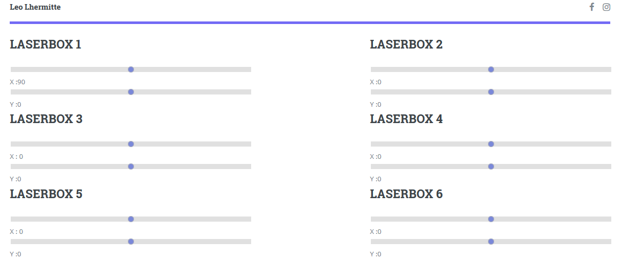
Basically, what I want to do with my interface is to be able to control in live each of the different laser. Also I want to be able to save all of the current positions of my lasers into different modes.
The idea then is to be able to load the different modes and then create loops with them !
I will not explain here all of my code because the detail of it is in my Interface and application programing week.
Here the .js script :
var wSockList,
    iState = 0,
    interval = null,
    intervalValue = 1000;

const onopen = function(esp, event) {
    //console.log(esp, "open socket");
};
const onclose = function(esp, event) {
    //console.log(esp, "close socket");
};
const onerror = function(esp, event) {
    //console.log(esp, event);
};
const onmessage = function(esp, event) {
    //console.log(esp, event);
};

function getWebsocket(ipAdrr, onOpen, onClose, onError, onMessage, port=81){
    var Wsock = new WebSocket('ws://' +ipAdrr+ ':'+port+'/');
    Wsock.onopen = onOpen;
    Wsock.onclose = onClose;
    Wsock.onerror = onError;
    Wsock.onmessage = onMessage;

    return Wsock;
}

function start(){
    wSockList = {
        ESP1 : getWebsocket('192.168.43.22', onopen, onclose, onerror, onmessage),
        ESP2 : getWebsocket('192.168.43.97', onopen, onclose, onerror, onmessage),
        ESP3 : getWebsocket('192.168.43.170', onopen, onclose, onerror, onmessage),
        ESP4 : getWebsocket('192.168.43.125', onopen, onclose, onerror, onmessage)
    }
}


function showValueESP(espWS, espMotorID, newValue, axe){
    document.getElementById(espMotorID).innerHTML=newValue;
    espWS.send(axe+newValue);
    //console.log(axe,newValue);
}

function laser(espWS,stateLaser,espLaserID){
    document.getElementById(espLaserID).innerHTML=stateLaser;
    espWS.send(stateLaser);
    //console.log(stateLaser);

}
function saveMode(modeID){
    console.log("save called");
    let confJ;
    let confL;
    let confModeJ;
    let confModeL;
    let espModeID;

    for (i=1;i<=4;i++){

        espModeID = modeID+"ESP"+i;
        //console.log(espModeID);

        confJ = {
            x : document.getElementById("outputTextxESP"+i).innerHTML,
            y : document.getElementById("outputTextyESP"+i).innerHTML,
            stateLaser : document.getElementById("stateLaserESP"+i).innerHTML
        }
        confL=JSON.stringify(confJ);
        //confModeJ = {espID : confL}
        //confModeL = JSON.stringify(confModeJ);
        localStorage.removeItem(modeID);
        localStorage.setItem(espModeID,confL);

        //console.log(i);
        //console.log("pute3");
    }
}

function loadMode(modeID){
    console.log("load called");
    let confModeJ;
    let confModeL;
    let confJ;
    let confL;
    let espModeID;
    let espAxe;
    let espMotorID;
    let newValue;
    let espLaserID;
    let stateLaser;

    //console.log(modeID);

    for (i=1;i<=4;i++){

        //console.log(i);

        espModeID = modeID+"ESP"+i;
        espID = "ESP"+i;
        espLaserID = "stateLaser"+espID;

        confModeL = localStorage.getItem(espModeID);
        confModeJ = JSON.parse(confModeL);
        //confL = confModeJ.espID;
        //confJ = JSON.parse(confL);

        //console.log(espModeID);
        espAxe = "x";
        espMotorID = "outputText" + espAxe + espID;
        newValue = confModeJ.x;
        //console.log(confModeJ.x);

        showValueESP(
            wSockList[espID],
            espMotorID,
            newValue,
            espAxe

        );

        espAxe = "y";
        espMotorID = "outputText" + espAxe + espID;
        newValue = confModeJ.y;
        //console.log(confModeJ.y);
        showValueESP(
            wSockList[espID],
            espMotorID,
            newValue,
            espAxe

        );

        stateLaser = confModeJ.stateLaser;
        //console.log(confModeJ.stateLaser);

        laser(
            wSockList[espID],
            stateLaser,
            espLaserID
        );
    }
}

function boucleControl(stateBoucle){

    if (stateBoucle == "on"){
        console.log("boucle on");

        interval = setInterval(boucle
            ,intervalValue);

    }

}

function boucle(){

    console.log("boucle");
    var tabMode=[
        'AESP',
        'BESP',
        'CESP',
        'DESP'
    ];

    loadMode(tabMode[iState]);
    iState++;
    if (iState >= 4){
        iState = 0;
        console.log(iState);
    }
    console.log(iState);

    return false;

}

$('.slider').on('input', function(){
    console.log($(this).val());
    var espID=$(this).data('esp');
    var espAxe=$(this).data('axe');
    var newValue = isNaN($(this).val()) ? undefined : $(this).val();

    if(newValue == undefined)
        return;
    var espMotorID = "outputText"+espAxe+espID;
    showValueESP(
        wSockList[espID],
        espMotorID,
        newValue,
        espAxe

    );


});
$('sliderTimer').on('input', function(){
    console.log("cocou");
    intervalValue = $(this).val();
    clearInterval(interval);
    boucleControl(stateBoucle);
    console.log(intervalValue);

});

$('.buttonlaser').on('click',function(){

    var espID=$(this).data('esp');
    var stateLaser=$(this).val();

    var espLaserID="stateLaser"+espID;
    console.log(espLaserID);

    laser(
        wSockList[espID],
        stateLaser,
        espLaserID
    );

});

$('.buttonModeSave').on('click',function(){

    var modeID=$(this).data('mode')+"ESP";
    //console.log('okokok');
    saveMode(modeID);
    console.log(modeID);
    return false;

});

$('.buttonModeLoad').on('click',function(){

    var modeID=$(this).data('mode')+"ESP";
    loadMode(modeID);
    //console.log(modeID);

    return false;

});


$('.buttonBoucle').on('click',function(){

    var stateBoucle = $(this).data('button');
    //console.log("coucouboucle");
    boucleControl(stateBoucle);

    if (stateBoucle == "off"){
        console.log("boucle off")
        clearInterval(interval);
    }
    //interval = setInterval(boucle
    //    ,5000);
    return false;

});
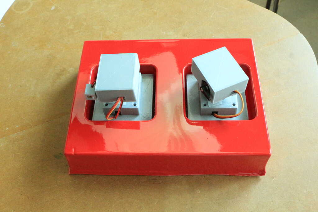
Okay, now we have some nices laserbox ! One good thing with this system is that they are really light. But that mean that they are also not very strong...
And basically my final project need to include some 2D design. Then the idea is to create a box in order to carry the laserbox !
Also, the idea is to be able to present a finished product. Even if the the idea is not to market my project, I think that is also important to think about this part. Lot of fablab project have not a great finish and this change a lot the perception that we have of them.
And at the time of market a product you will some method to package of finish product.
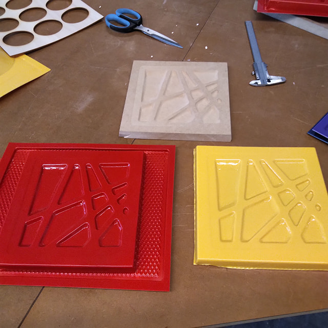
The box that I want to do is a box made by laser cutting. Inside of the box I will add a thermoformed support in order to maintain the different laserbox in place.
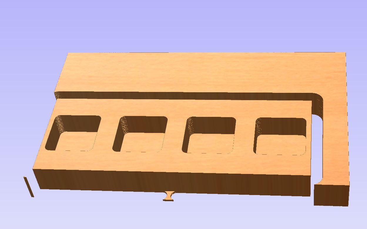
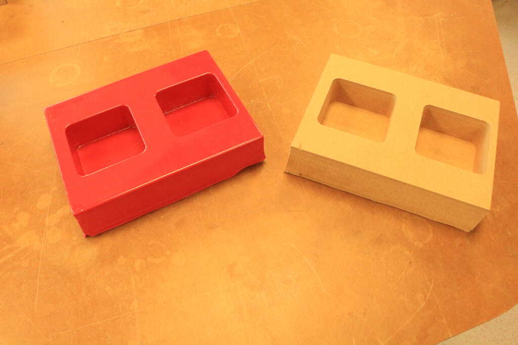
To do this I will mill a mold and then thermoformed it. Then I will design and cut some 3mm MDF in order to make the box !
In a first time I juste make some 2D design using rhino 6. I designed some rectangles and square. This part will be the mold that I will thermoform !
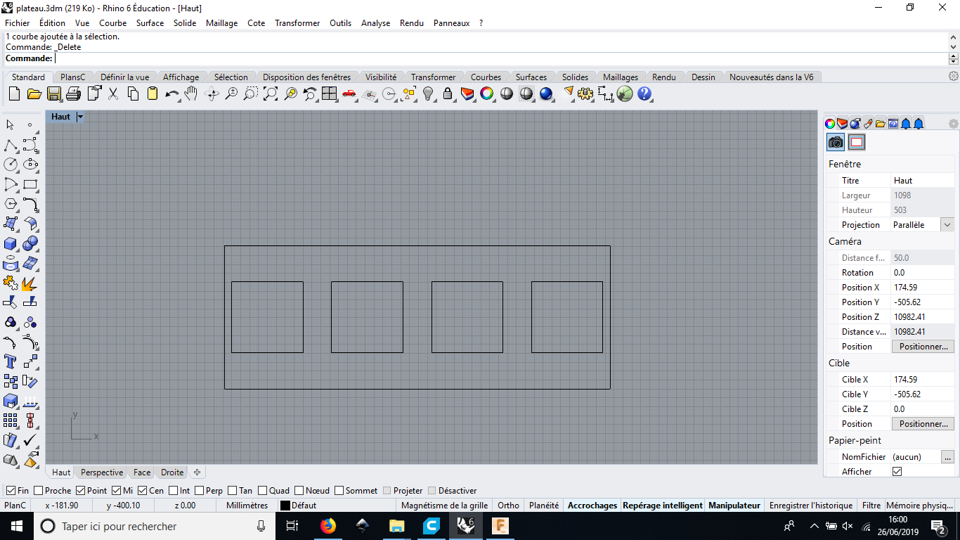
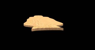
Now let's machine it ! Into a big plate of wood. The wood that I used is a 50mm MDF plate.
In order to know the feed and speed and then have optimals parameters. I used the chipload as I maid in my something big week.
The chip load of the MDF is about .025"-.027" for a bit of more than 1/2".
This is the parameters I use:
| Diameter | Depth | Step-over | Spindle speed | Feedrate | Plunge speed |
|---|---|---|---|---|---|
| 18mm | 9mm | 70% | 3000tr/min | 60mm/s | 30mm/s |
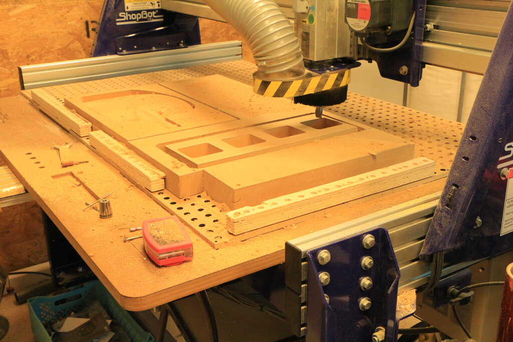
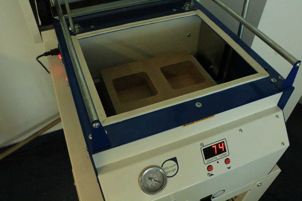
At the moment where I made this design I was in the rush and I made a mistake... The size of the mold has to be able to go into the thermoforming machine... Then I decided to cut it using a saw. Hopefuly MDF is really easy to saw.
Also, as I explained in my wildcard week the MDF is perfect for creating thermoforming mold because it is porous and then the vacum pump can easly suck up the air and then the plastic !
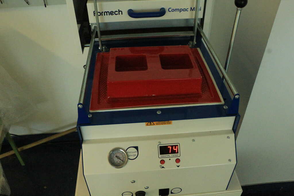
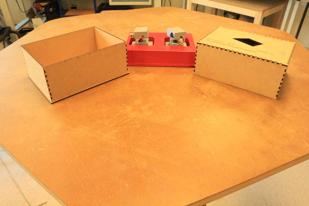
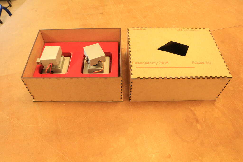
And this is the result ! I'm really happy because the Laserbox are perfectly fit with the plastic part, I can easly move them out of the support but they can not move when the box is closed. This guarantee their safety.
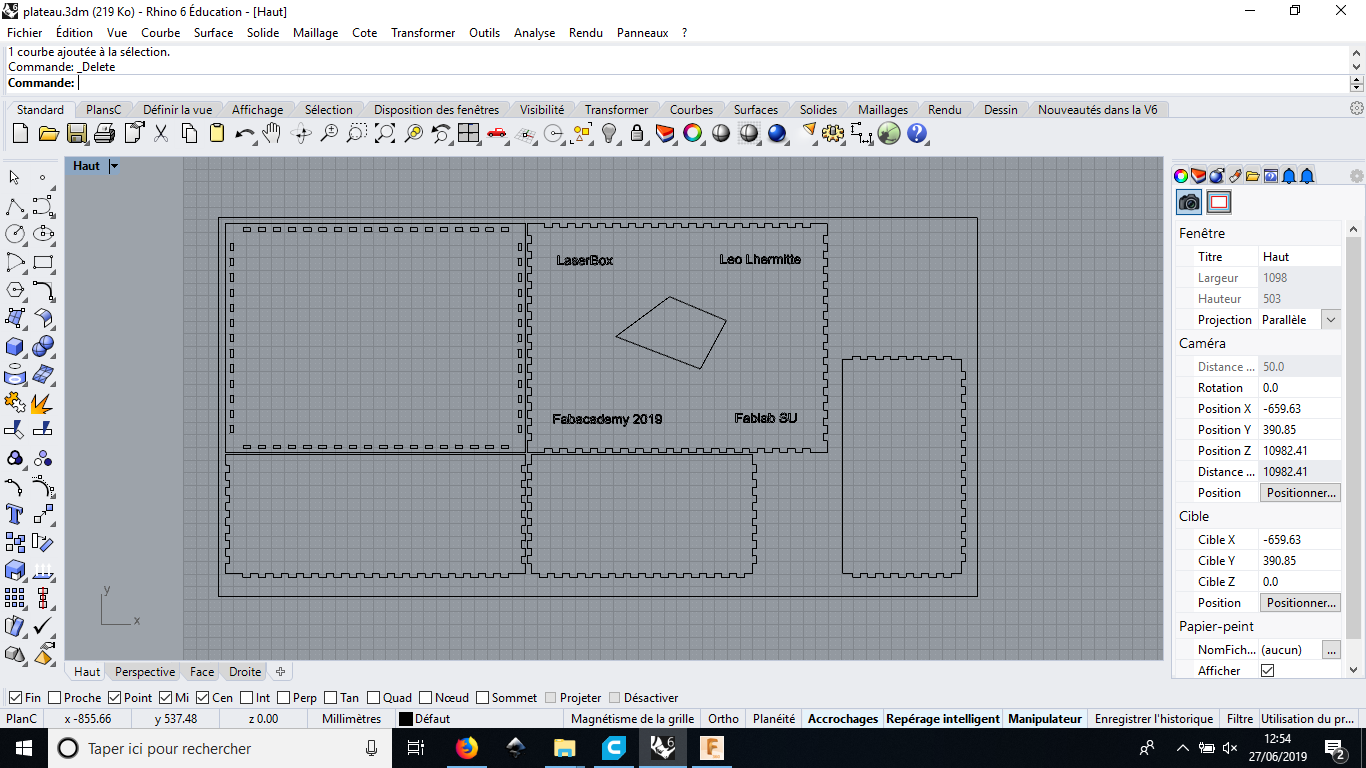
Now let's make the box. Same as the precedent part I designed the box with Rhino 6. In order to have strong box I added a lot of fitting part ! And I added an offset of 0.3mm in order to be able to fit the different parts. I choose this offset because of the test that we maid during the laser cutting week !
I cut it with a Speedy 100 Trotec.
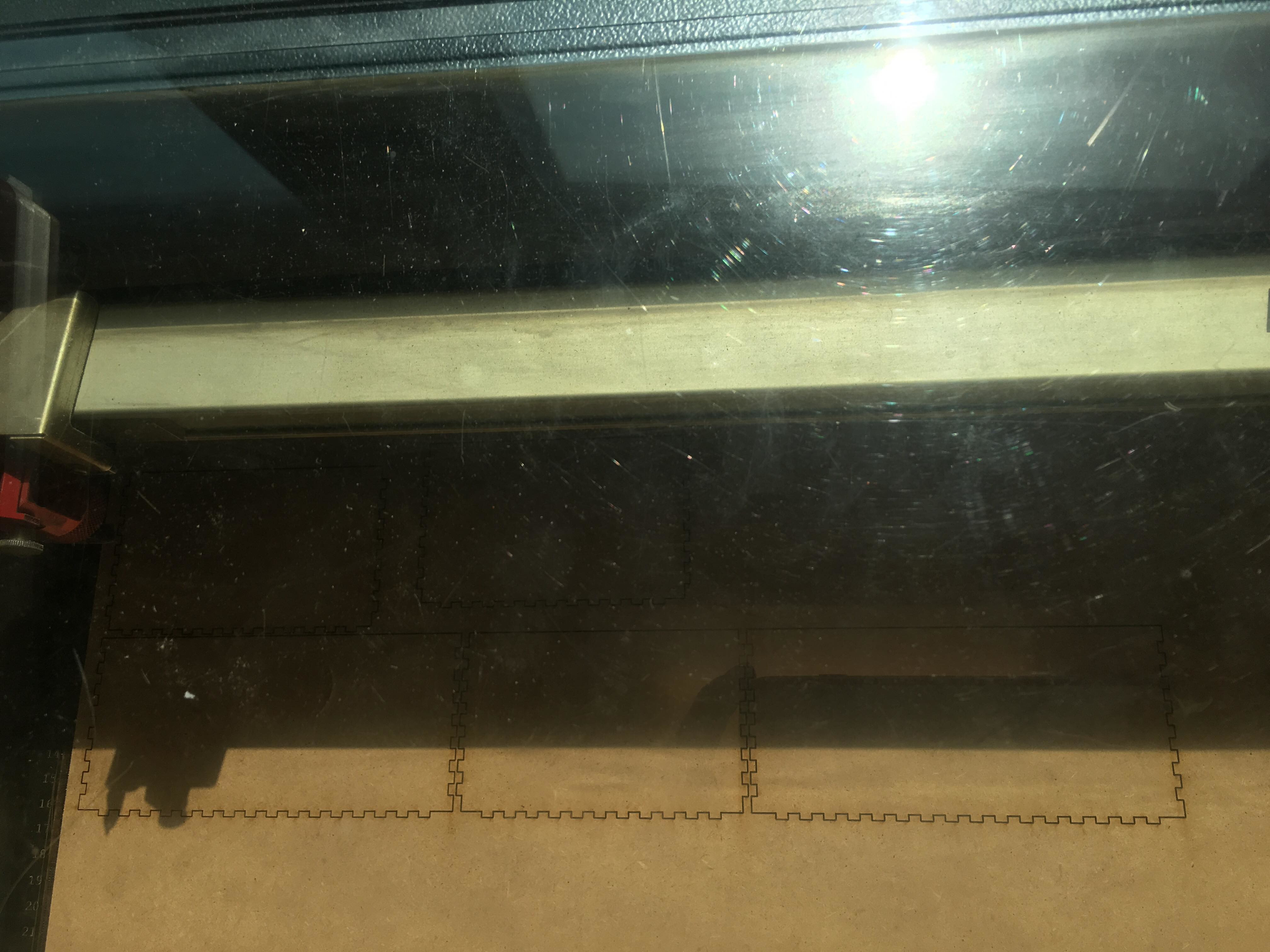
Now let's assembly the different parts.
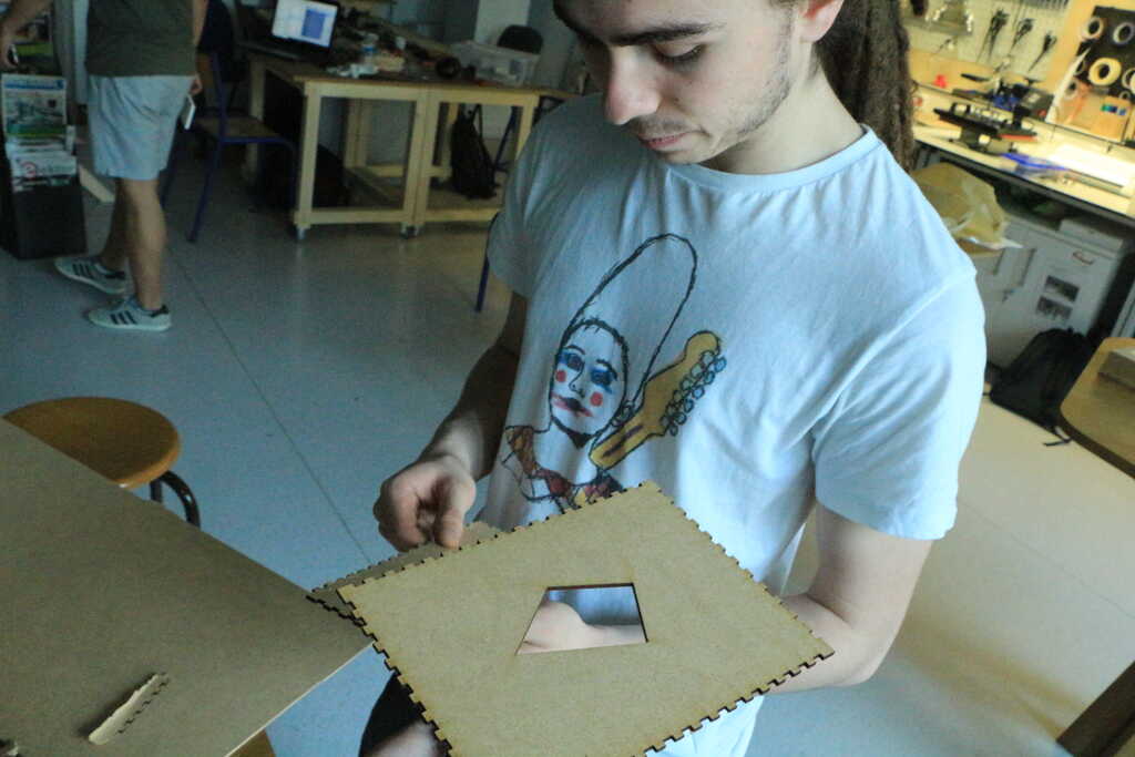
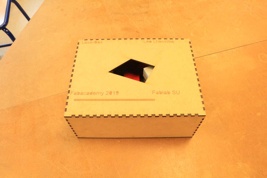
And finally, this is the result !!!
Also I'm very happy with this box because all of the parts are perfectly fit and I didn't have to add glue only some mallet knock.
And as expected the size of the plastic support is also perfectly fit into the box. Again the safety of my project is guarantee !
Project developement
Intelectual property
Wildcard Week
Machine design
Interface

Mechanical Design
Networking and communications
Application and Implication
Output device
Input device
Molding and casting
Embedded programming
Computer-Controlled Machining
Electronics design
3D scanning and printing
Electronic production
Computer controlled cutting
Computer-aided design

Versioning and Website
Idea of my final project
How to modelise a longboard
For any suggestion, help or featured project