
Project developement
3D and modeling are a big part of my maker background. I have already made some things in 3D, using differents programs like blender, sketchup or principaly rhinoceros. This week is the occasion for me to discover a lot of new tools.
I plan to use this week in order to sketch and modelise somes concepts and pieces about my final project. For this I have to choose the good software for each type of 3D model that I want.
In a first time I have listed and make somes research about a lot of tools in order to understand there role. Finaly I have a little list of very differents tools and a little idea of how I will use them.
This tiny light-weighted software is the core of voxelart, since it is capable of many things : just edit, paint and move your voxels in a cubic grid, then animated them and render them with the powerful integrated renderer.
Magicavoxel is a really powerful soft, fresh and easy to use ! Basicaly you can add (Attach), remove matter (Erased), or paint with differents shape or commands.
The logic of the software is really easy to understand and the algorithm works very well.
I have decided to try this soft because of part of a video where you can see someone animate his 3d model very easily.
This give me the idea to make the same with for my laser project.
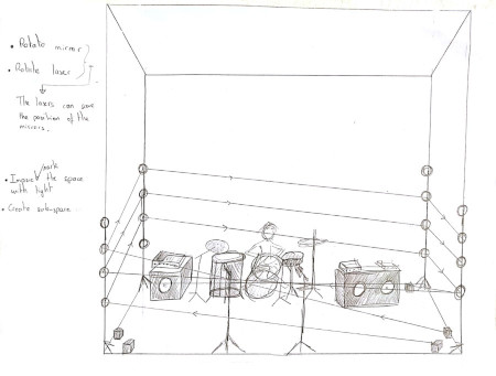
Basicaly this what I want to modelise using Magicavoxel.
I have started my modelisation by testing the differents type of erasing the voxels. You can choose the form of your erased (square,circle, cone, etc...). Whith the same method I have tried differents type of adding the voxels. After this I was able to know how to modelise my idea.
Starting to modelise my idea the first step I have decided was to make the structure on wich the mirrors will be mounted. To make this I used the L option combine with Attach in order to add matter. Simultaneously, I active the X Y mirror then when I make one of my rod 3 other will be placed symetricaly on each corner of my stage. Using the same method I have add some whites voxels to represent my mirrors. And some green for the lasers.
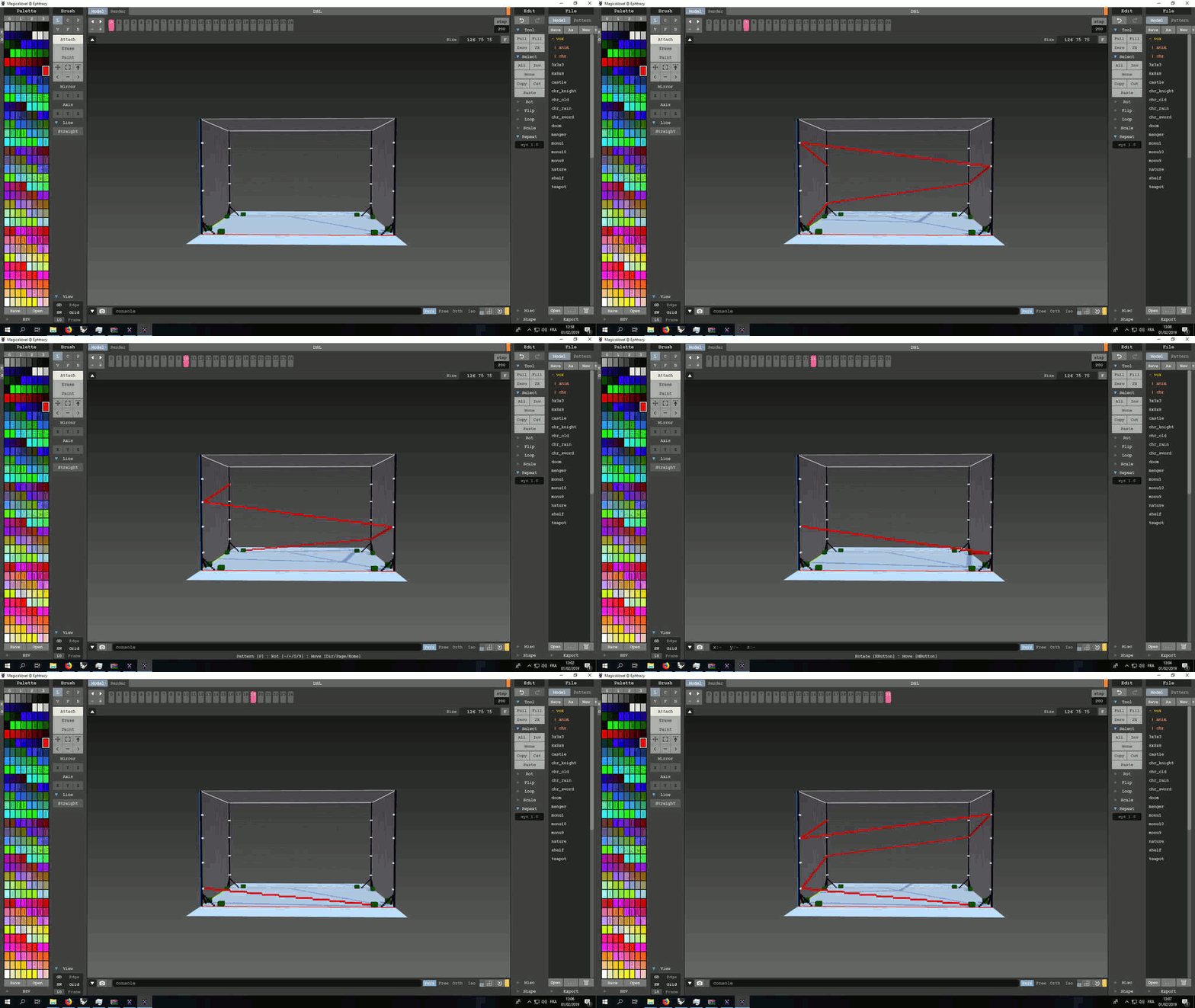
Afterwards, all I have to do was to modelise my laser beam. To do this my constraint was to have all adding beam on a different frame. Because I want also to to animate it in order to make like a 3D spiral. Whith this animation I will be able to have a more concret vision of my idea with the movements. Aaaand Magicavoxel to this very well ! The only thing is to download the 0.98.x version rather than the last version because for now the developpers team have deleted the animation menu.
This is the method I used to save each additional beam in a new frame.
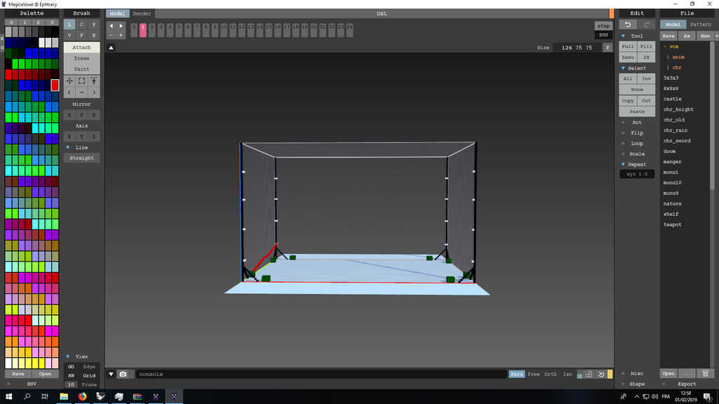
Here you can see one of the beam. In order to animate it I need 6 beams begining successively from the 4 corners. Then I will have 24 frame with wich I will create my animation.
GIMP is an acronym for GNU Image Manipulation Program. It is a freely distributed program for such tasks as photo retouching, image composition and image authoring. It has many capabilities.
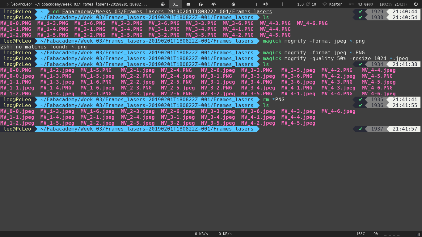
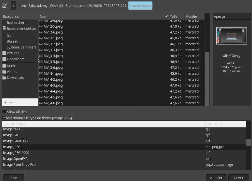
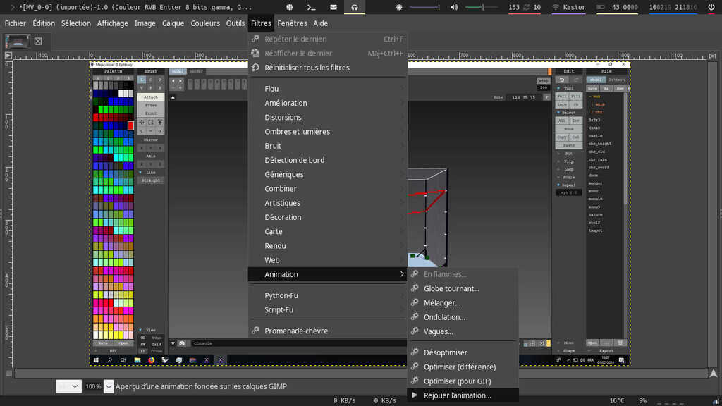
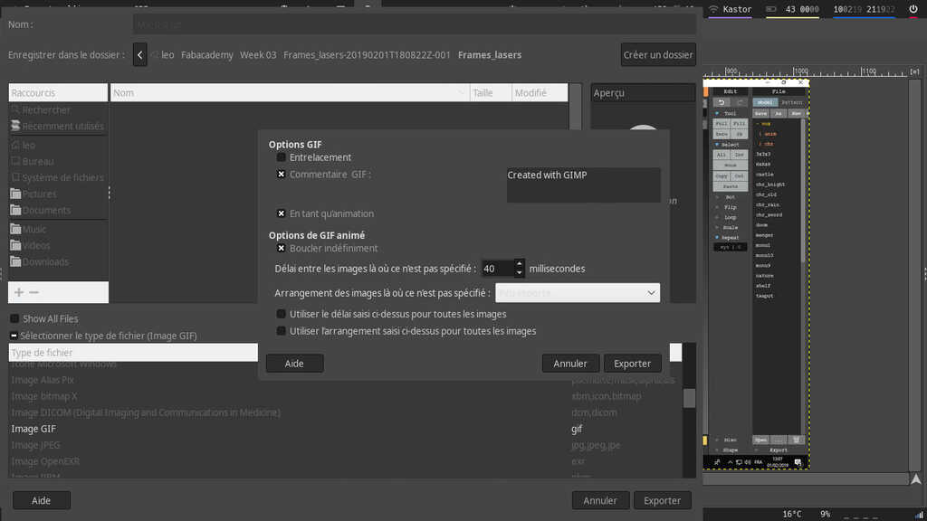
Basicaly, I want to use Gimp in order to create an animated image with my 24 frames coming from magicavoxel. The method to do it is really simple :
mogrify -format jpeg *.png and magick mogrify -quality 50% -resize 1024 *.jpeg .
FreeCAD is a general purpose parametric 3D computer-aided design (CAD) modeling application, made primarily to design real-life objects. Parametric modeling is a type of modeling where the shapes of the 3D objects you design are controlled by parameters.
In my project I want to mount 2 servo-motor on top of each other and then mount a mirror on my superior servo. I make this because I want to have the possibility to have 2 axes of rotation. In a first time I will try to use this little servo-motor :
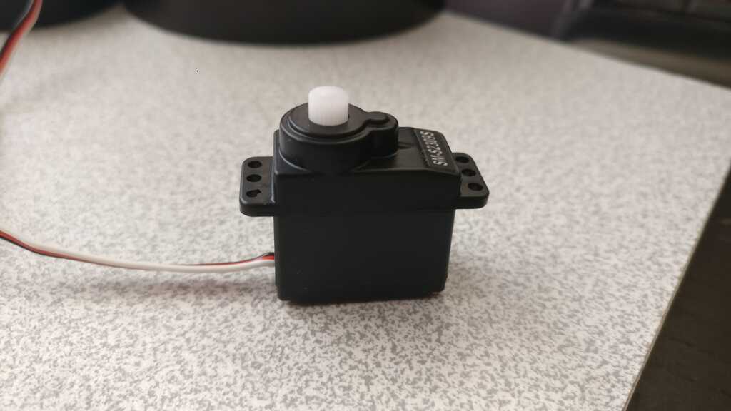
The first step is to modelise it. When I modelise something my method is to break an element down into its components. The first component we have (and basicaly the most simple) is a right-angled parallelepiped. The FreeCAD logic bring you to make in a first time a 2D sktech and then extrude it in order to create a solid.
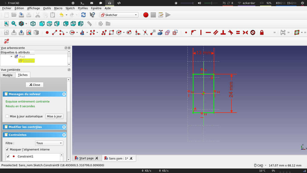
You can see on this picture the first rectangle I made. In order to make it I have created a new sketch on the XY plan. The I draw it with the rectangle 2 points tool. You can also see that it is totally green, wich means that my sketch is fully constraint. Basicaly, you won't be able to move or modify it with your mouse. The only way to modify it is to modify the constraint. On this sketch in order to fully constraint it I have a :
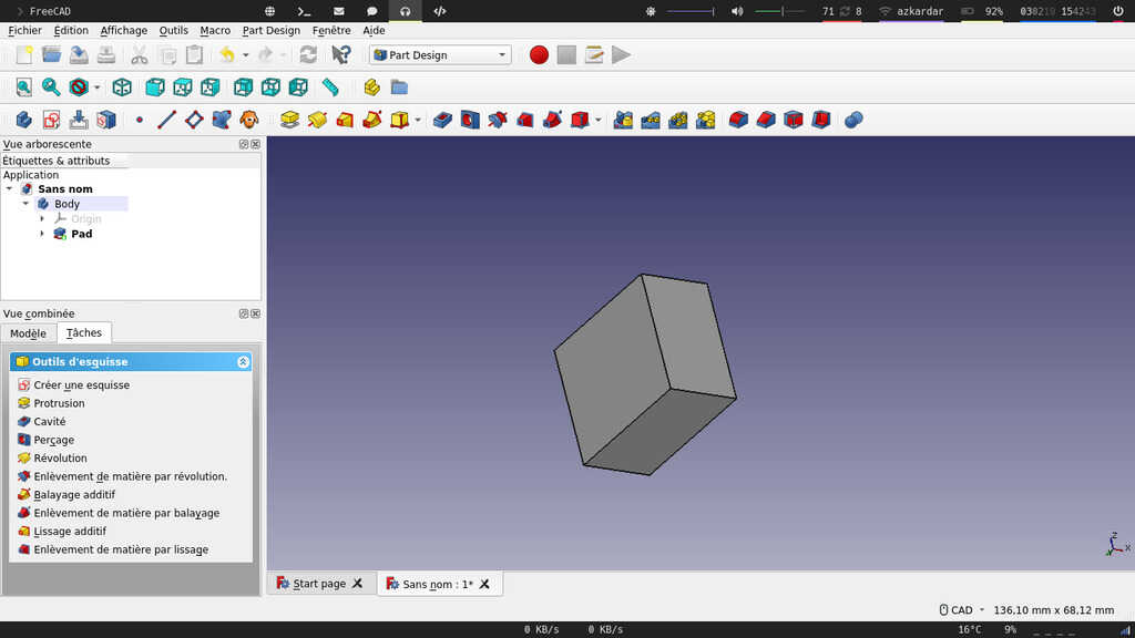
The interesting thing with parametric design is the flexibility of your modelisation. If I want to change the size of my extrusion I just have to change the size of my first rectangle, then the extrusion size will automaticaly change.
Notes : In fact parametric design is not only limited to a direct relation beetwen sketch and 3D models. With it you can also create mathematicals formula depending of some variables and many other things !
The second sketch is the top part of the piece :
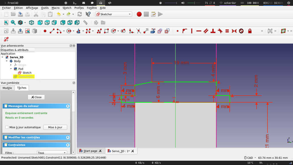
To do this, I clicked on the side where I wanted to draw my sketch, then I choose draw a sketch on the Task Menu . I have used the polylines tool to draw the global shape of my sketch. And I use "M" button in order to change the mode of my polyline then I can easly make 90° angle. Afterwards, I just add some constraints to my sketch.
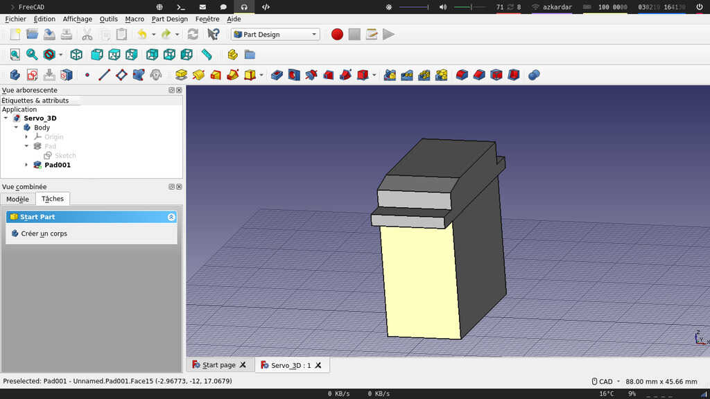
In order to make a hole this is exactly the same methodology of making an extrusion. I just use the hole tool. But here the thing is to not repeat the same thing for each hole. I have used the multi-transform tool in wich you can add a succession of transformations on an already existing fonction.
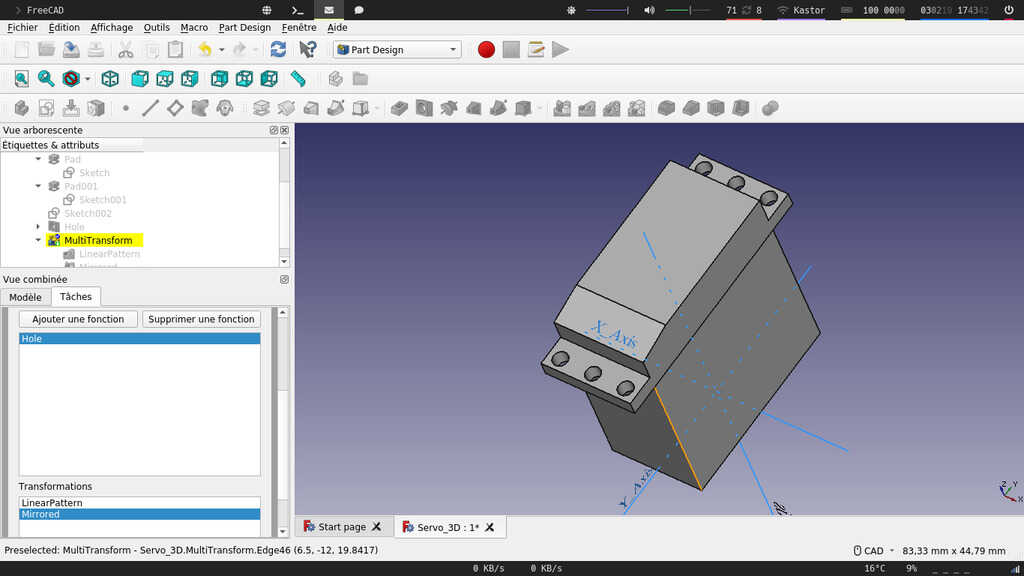
And finally I have made the top circular part with the same methodology.
The purpose of this modelisation was to create a piece wich allow to mount a servo on top of each other. To do this, first I have copied and moved a second servo motor using the position properties .
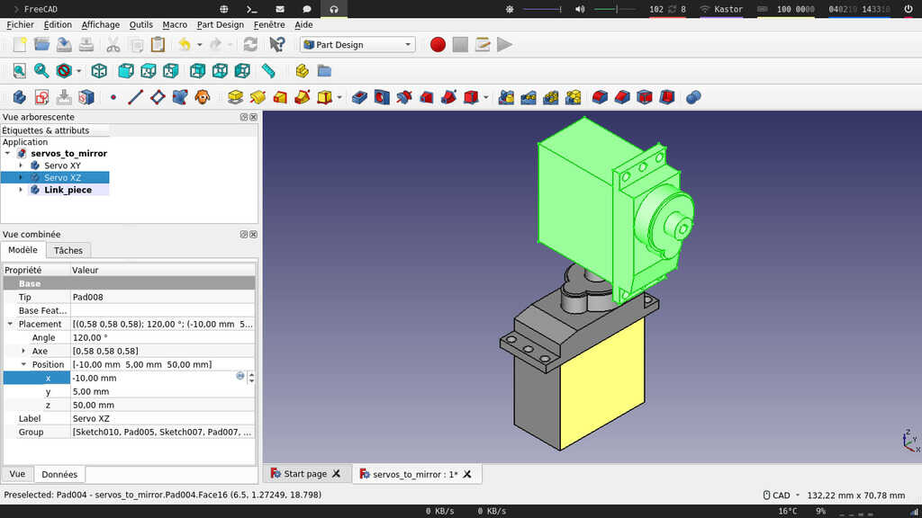
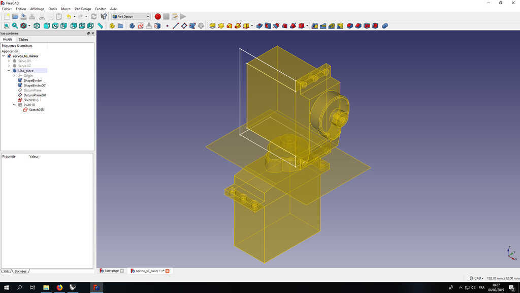
Here this is the part a little bit more tricky. In order to make the new piece I have created a new body called "Link_piece" but in an empty body you can only sketch on the basics reference plan and you can't have the attachement points from external geometry. In the freeCAD logic in order to make this you have to "copy" your other body with a special status of "shape Binder".
Creates a datum shape binder from a selected Body inside the active Body. A shape binder is a reference object that links to edges or faces from another Body. The shape binder object displays as translucent yellow in the 3D view.
Then by holding on the attachement points of my servo motor I can sketch the shape of the piece
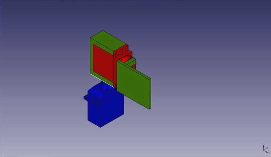
And finally this is in green the pieces wich will sustain my second servo and my mirror. In order to reuse the 3D model with another software I have saved a .stl version.
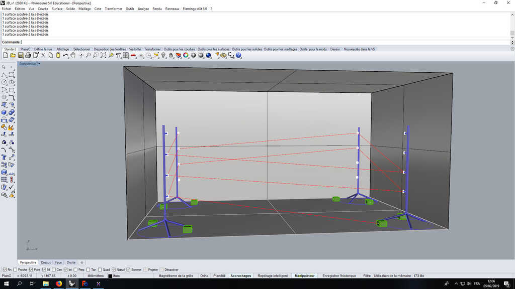
Okayy, Rhinoceros is my favorite CAD software, I use it very often. This a really powerful software wich allow you to generates surfaces - very well :p - . It is very helpful in order to modelise very complexe surfaces. Or in order to represent a space, wich is exactly my case.
I had already made a little structure with Rhino 5 and I figured that I use it with the piece I had just modelised. To do this I have used the import fonction in order to import my .stl file. Afterwards, I just moved basicaly my object on the rods.
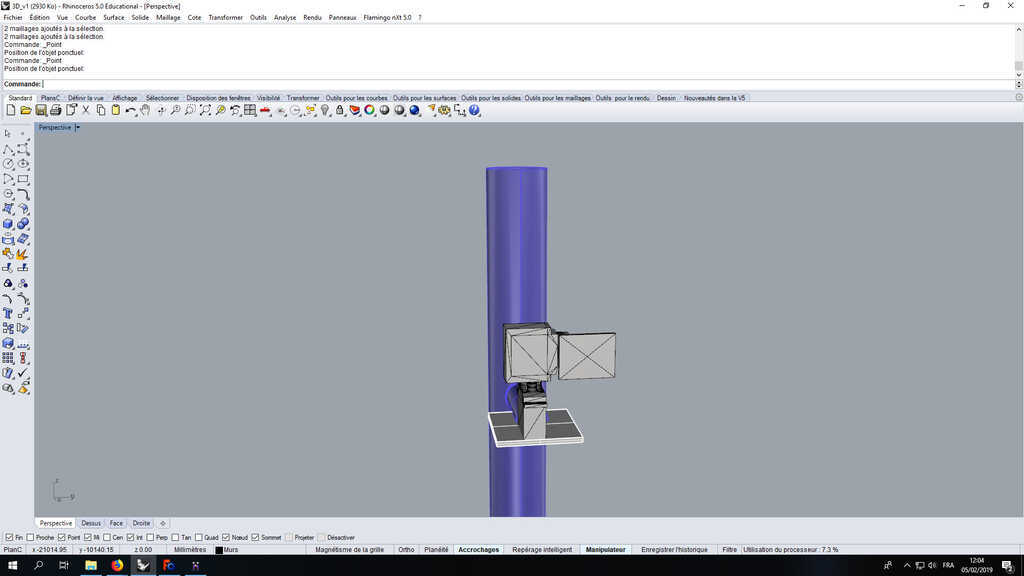
I have copied them 4 times and placed them in a "box" wich represent my stage.
This week was for me very exiting because of the assignement. The Computer Aided design is one of my favorite part of my maker work ! Then it was the occasion to discover new tools and software, take the time to learned new things !
See you next week ;)
Rhino file Magicavoxel file STL fileSee you later space cowboy