
Project developement
--> Link to the group assignement page <--
Hi, this week is for me the occasion to discover and test some stuffs about surfaces, and 3D scan !
Focused on my Fabacademy and all the new things that I am learning, I try to keep an eye on my goal to join a architecture school for the next years. Then for me, this week is a really good occasion to try things about 3D surfaces and specialy about biomorphic structure. I think I will try to use grasshopper to design the model I will print !
Always, in the architecture field, the world of the scanning 3D and the photogrammetry is really huge, and allow to represent and model spaces.
This week after a little search on the Niel's documentation I find out a method using visualSFM and meshlab . This method seems to be really light for computer. I had also heard about meshlab and I wanted to try it.
Whats is photogrammetry ? At this state I know that use images to reconstruct 3D models and thats all...
After somes researches about visualSFM, I understand that this software is using algorithms to compute the similar points on differents images, taken from differents point of view. Then a cloud of points will be created in 3 dimensions. And then with meshLab you are able to map surfaces linking the points in order to create a mesh.
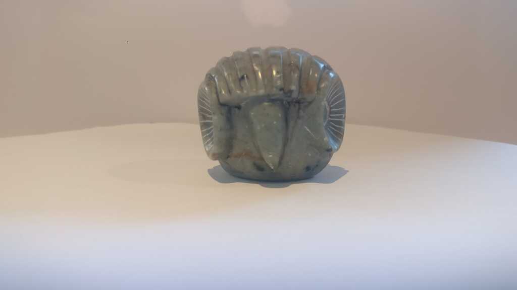
Then the first that I have make is to take some pictures of a little inca statue. In order to have images of the object form different point of view I have put the object on my micro-waves tray, I have covered all the view with white paper, in order to delete the parasites points coming from the surroundings objects. I have turned the object step by step, and I took about 120 pictures.
From now I'm following the Mathis Fantin's tutorial. The first thing then is to import your pictures. To do this, just click on the folder icon the top-left corner and imports all of your pictures by selecyings them.
And you should have something like this :
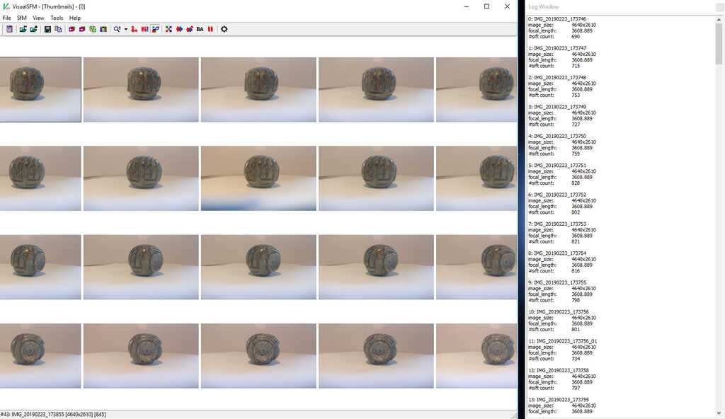
Now all the pictures are imported in the software.
The next step is to search the feature matches using the SfM / Pairwise Matching / Compute Missing Match. Or click on the icon described in the following picture. This function will compare all of the pictures two by two and will found all matching points beetwen the differents pictures.

The next step is to reconstruct the cloud of points from the matching point of the previous step. You can do it from SfM / Reconstruct 3D or clicking the following icon.

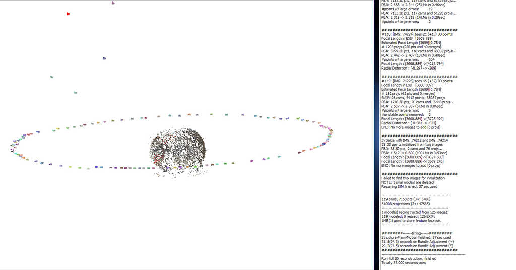
Now you should have a cloud of points looking like your object. If you have a lot of points off-centre of the object, maybe you will have to re-do the shooting. This may be because of too many objects in the field of view or because of a bad luminosity.
And finally export the data using SfM / Run CMVS/PMVS or clicking on the following icon. Now your points are able to be open with MeshLab.

MeshLab is a software allowing to add differents transformations and filters on a cloud of points and meshs. Each point is caracterised by 3 (X/Y/Z) coordonates, a color and a normal vector to the "micosurface" corresponding to point. But our cloud of points haven't any normal vector, then of the step will be to add normal vector for each point.
Let's start, the first to do is to import the cloud of points. You should have a .mlp file from the last step. Meshlab is able to open this type of file. (Be careful, following your version of VisualSFM you may be have .ply file. If this is your case, open it)
You should see something like this :
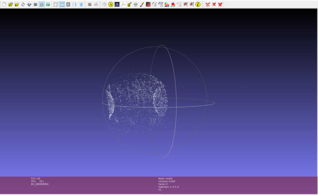
Delete the isolated points or group of points corresponding to the artefacts of the "dense reconstruction". This step allow you to only keep the points you want to create your modelisation. Point set / Estimate radius from density This function compute the distance average beetwen the points of your model. After, use Selection / Conditional Vertex Selection and choose rad > 0.01 as parameter. Now you have to module the value in order to keep only the point you want.
In my case, the points I wanted to delete was to close of the other points and after a lot of try I chose to let them and see what will be the result.
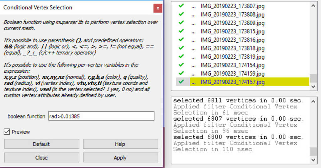
Ok, the next steps are just some configurations and tests to do in order to find out the best parameters for your case.
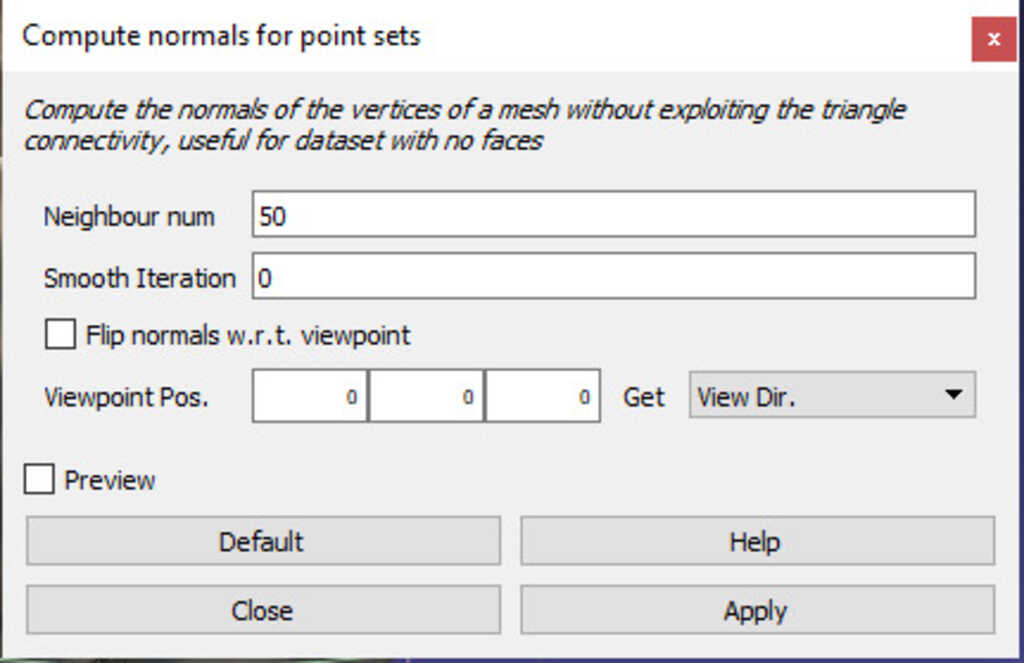
As, I have said earlier, we have to create normal vectors to each point.
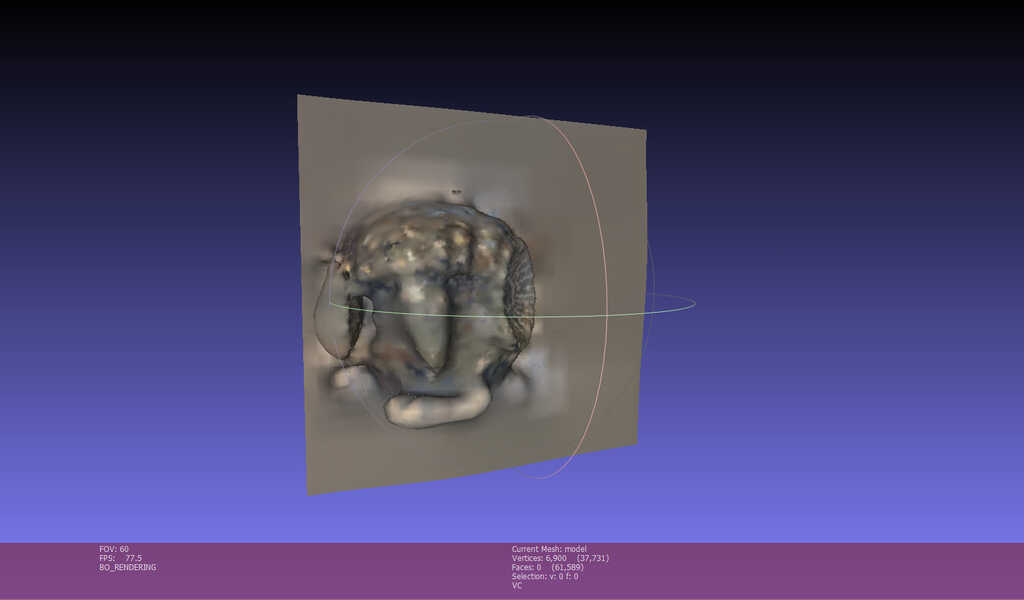
To do this, Point Set / Compute Normals for Point Set . In the documentation I have followed, its specify to check the Flip normals w.r.t. viewpoint case and put a -1000 in the field of coordonate. In my case when I check this case, I got a very strange result in the follwing step. I think this is because I have made moved the object et not the point of view of the camera. And the the Flip normals w.r.t. viewpoint case able to have coherent direction for each vector if your surface is not continue. In my case the bug appear on the top of the object, where there was not a lot of point (only 3 pictures). Then at this place the vector where strangely oriented.
The bug :
After, by following the tutorial, the last big step is to use Remeshing, Simplification and reconstruction / Screened Poisson Surface Recontrucion In the parameters of this function the reconstruction depht is corresponding to an octree and the depht is the level of detail you will have. I recomand you to stay beetwen 6 and 12.
And this is the first result !!
I'm impressed by the result, even without the color transfert the result is not so bad... The result is not extremely detailled but for the compute time (about 1 minute at all) this is really impressed !
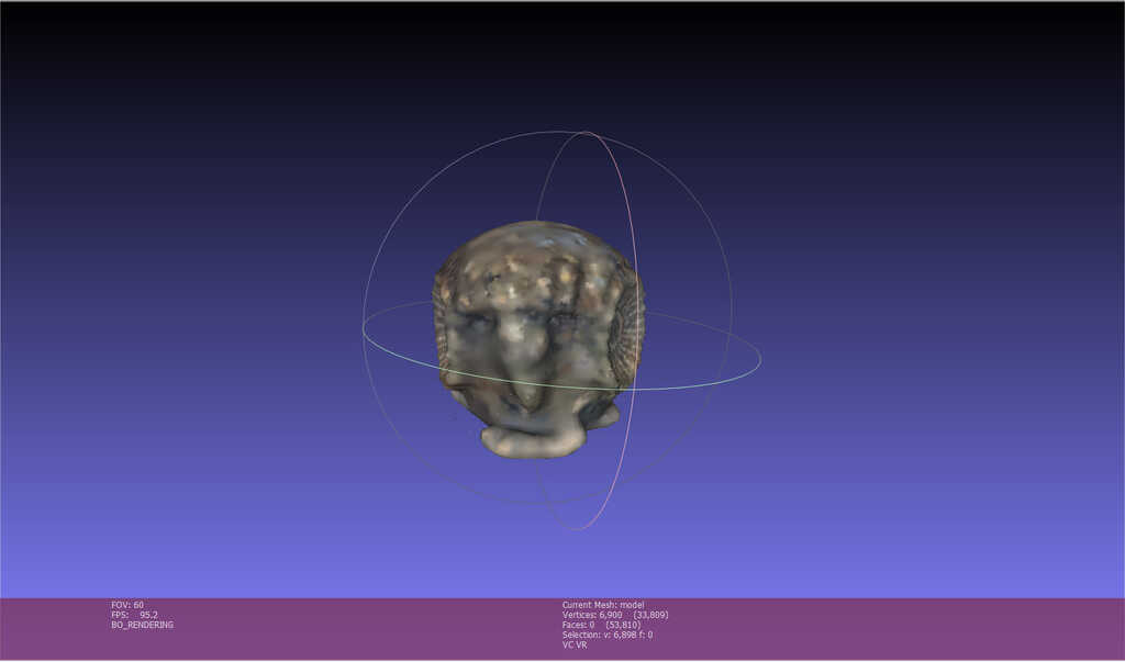
Now you can add a transfer color by using Sampling / Vertex Attribute transfer checking the color case.
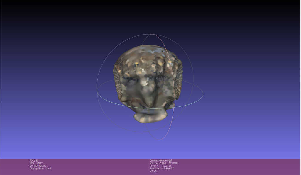
But in the tutorial, the author recomand to use another function in order to increase the result. The method is to use Remeshing, simplification and reconstruction / Subdivision surfaces : LS3 Loop and Sampling / Vertex Attribute Transfer checking the transfer geometry case.
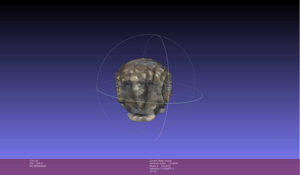
The result is really bad, and even with changing some parameters the result are really uggly.
After my try with VisualSFM and MeshLab, my instructor told me about a soft called meshroom . I check some models on sketchfab and the result looks great !
Then I have decided to try it !
I will not explain the process here, but this is really easy. Basicaly, you just ahve to import some pictures and click on start. The software is composed by a list of modules linked beetwen them. The default workflow loaded reproduce the same step I had explain above. You can change the parameters of all of them, add and take-off.
After some test, my computer crashed 3 times (I5-4670 (3,4GHz) and GTX 770). I decided to install the GPU optimisation for computing called cuda and after 3 hours of compute, this is the result !!For designers who are exploring new shapes using generative algorithms, Grasshopper is a graphical algorithm editor tightly integrated with Rhino’s 3-D modeling tools.
At the begining of the week, my idee was to make some research about repetitive surfaces like taffoni . I find this type of surfaces very mesmerizing and I love lost my mind into they curves and shapes. I was thinking about reproduce them, and making some research about grasshopper and surfaces like them, I found out a methematical object called Gyroid
A gyroid is an infinitely connected triply periodic minimal surface discovered by Alan Schoen in 1970.
Put it this way, its very difficult to visualise whats it looks like ^^. But don' worry we will see one as soon as possible :D
Concerning grasshopper, I'm a fully beginer. In order to modelise one gyroid I inspered myself with a forum page speaking about gyroid. One person had put a picture of his grasshopper file and I have used it to create my own gyroid. In order to create this workflow and based on the same method of the topic I use millipede and weaverbird wich are some free plug-in of grasshopper.
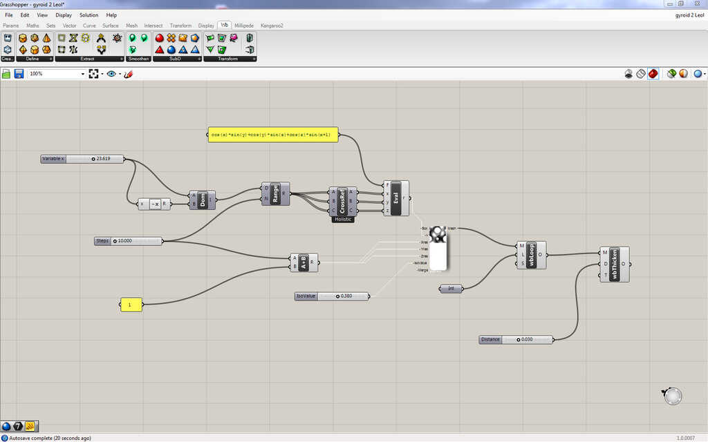
Basicaly, the thing with generative modelisation is to clearly understand the mathematical process in order to have structure of you algorithm. Then, the first step si to create a function using evaluate of the math module. This function take in parameter :
In order to give a litteral expression use the yellow icon bloc note if the basic tools. Then you can add the expression. The litteral expression of a gyroid is sin(x)*cos(y) + sin(y)*cos(z)+sin(z)*cos(x) = 0 in our case dont put the "= 0". And in order to give the 3 variables we will create a domain.
To do this, you can add a cursor and and link it to a -x function. Link them into a domain block. After that, we will create a range beetwen the resolution we want for our model and the domain we have created. I will explain later how to make the resolution part, for now just link the domain to the N inputof the range block.
The next step is to create cross reference beetween the list of different numbers we have. A very good topic about what is it and how it work
Then just link the output of the cross reference into the input X/Y/Z of the evaluate function.
You should have something like this :
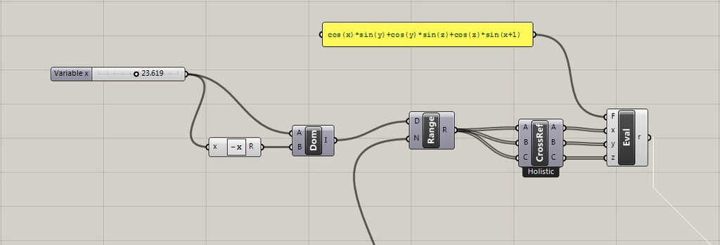
The second part of our workflow is the resolution part. It will define the X/Y/Z resolution of the surface we will generate, and the second input our range block. This part pretty easy. You just ave to create a cursor, link the cursor to N input of the range block and also to addition block. Aferwards, just create a value of 1 and in a yellow card and link it to the second input of the addition block.
You should have somethink like this :
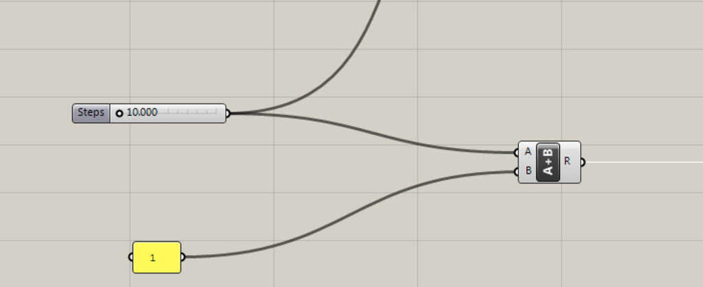
Now we have almost all of the data we need to generate our surfaces. The only things left are the generation blocks.
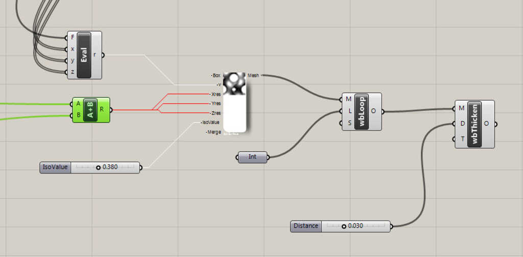
In a first time, we will use a block of millipede : IsoSurface . Just link the result of our evaluate function block into the v input of the IsoSurface block. Afterwards, just link the output of the resolution part to the Xres, Yres and Zres input. Just one more think in order to fully set-up the IsoSurafce block, create a cursor and link it to the IsoValue input. (His value must be really small, beetwen 0 and 1)
I will explain in images the role of each part but, for now let's finish to patch all of the workflow !
Basicaly, the IsoSurface give a surfaces similar to big triangles with different orientation. Then we use weaverbird to made something more smooth. In the weaverbird panel choose the blue icon loop link the M input to the output of the IsoSurface and just add a integer value set to 1 and link to the L input in order to set the block in "smooth" mode.
The last thing to do is to add a thickness in order to create a closed polysurface and not just a surface ! The block is also a part of weaverbird. In order to make it work, link the output of the loop block to the M input. And add a cursor linked to the D input to choose different value.
And this is it, now all of the workflow is created and it should look like this :
Global vision :
Ok, now I will describe visually, the role of some important block of our model.
Below, we have 3 pictures, we can have this result by linking on coordonate of our function (X/Y/Z) directly in the evaluate function, without passing through the cross reference (only for one coordonate). The result is the projection of our trigonometric function on one plan and extruded until the border of the cube. With this visualisation, we clearly understand the role of the cross reference.
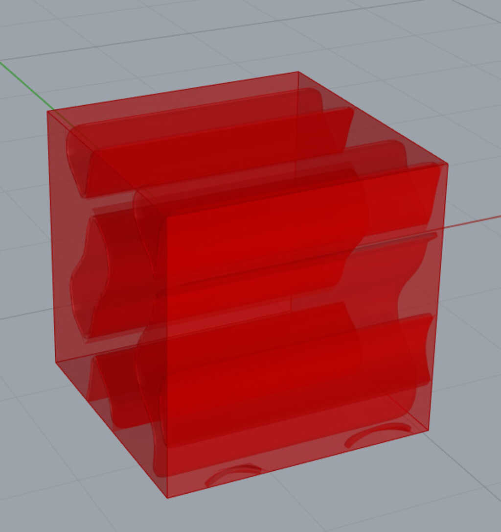
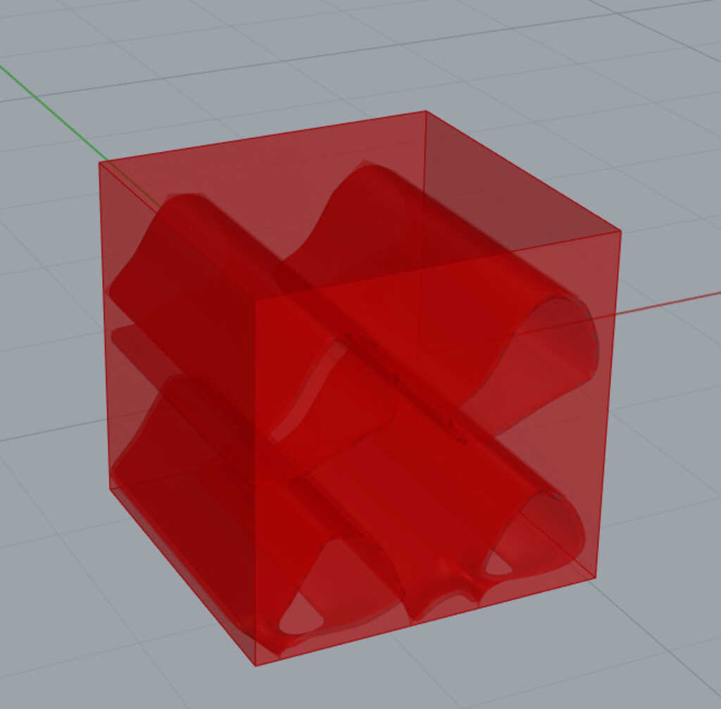
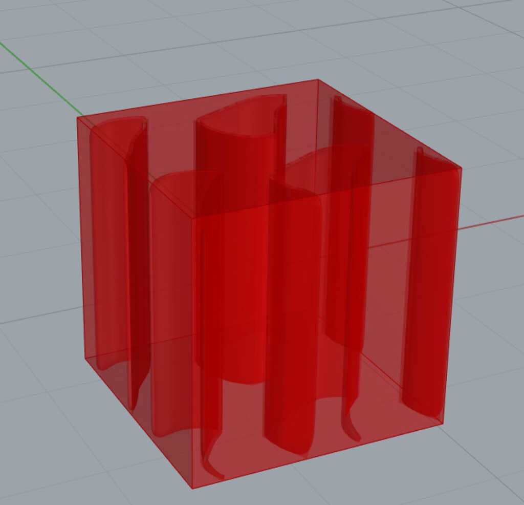
The cross reference allow to "cross match" the coordonates in X, Y and Z.
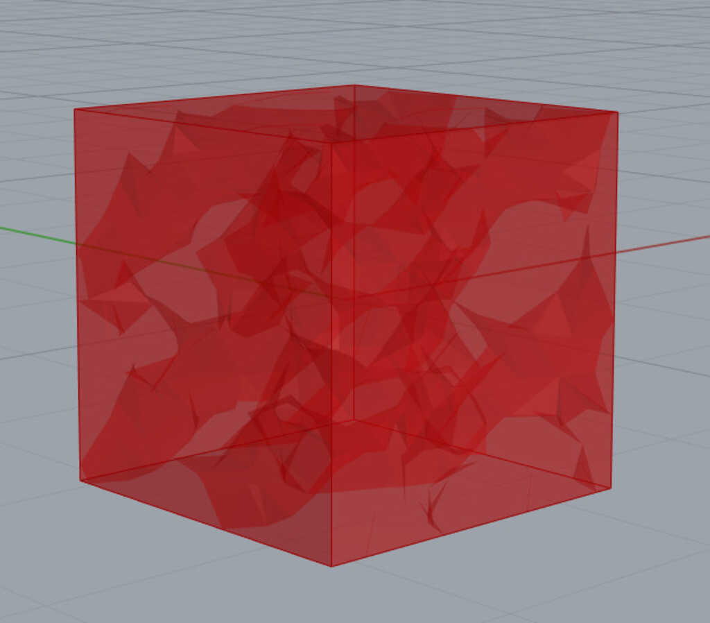
Now let's see the role of the weaverbird loop.
This without the weaverbird loop :
And now with...
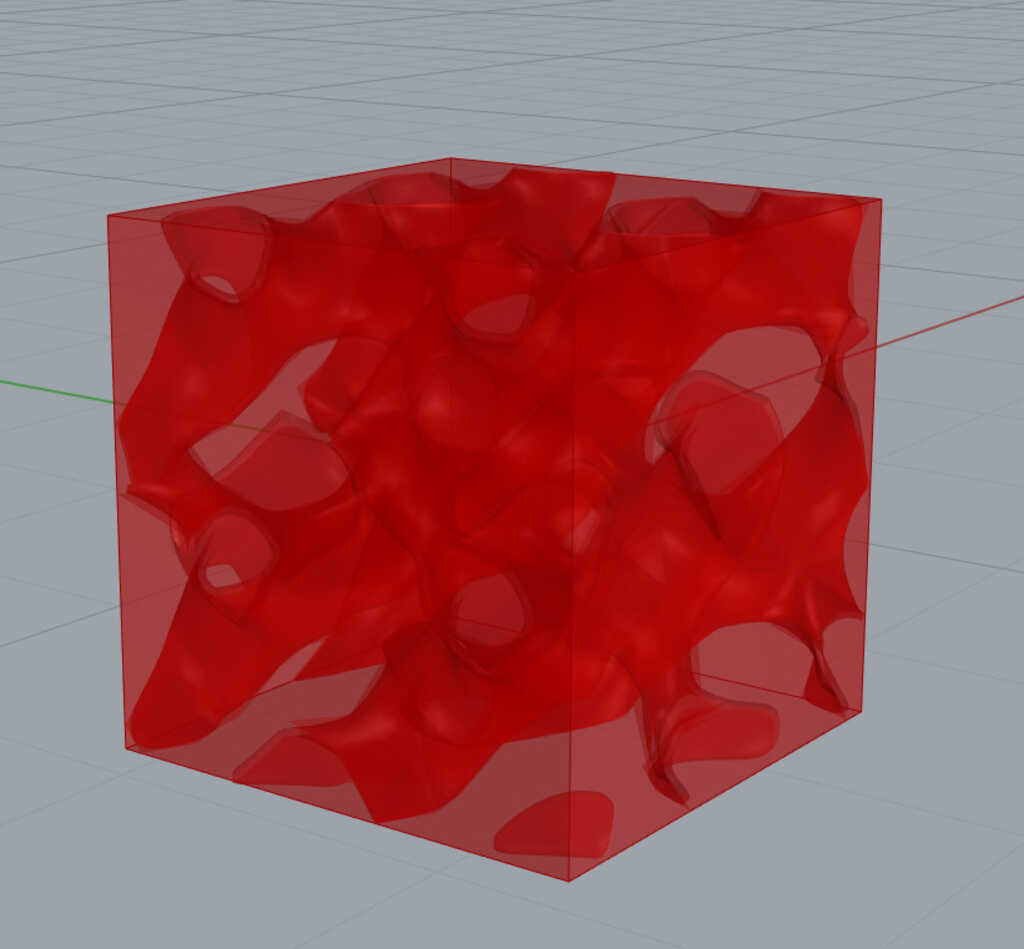
As you can see the IsoSurface block generate a surface without curves. The loop subdivision will compute the intersection of the surfaces and will create curves beetwen them. But be careful, don't forget to set the L input of the loop to 2, else the result must not so smooth...
And finally, the IsoValue. In our case the IsoValue cursor will determinate the "size" of the holes in our gyroid. Playing with it, we can have some fun result !
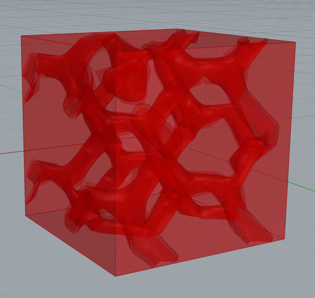
Obviously, some other parameters will modify our final model but I will not explain all of them here. All the files are downloadable on the bottom of the page or with sketchfab modules.
And now before printing this incredible object I have made some nice render for the pleasure of our eyes !
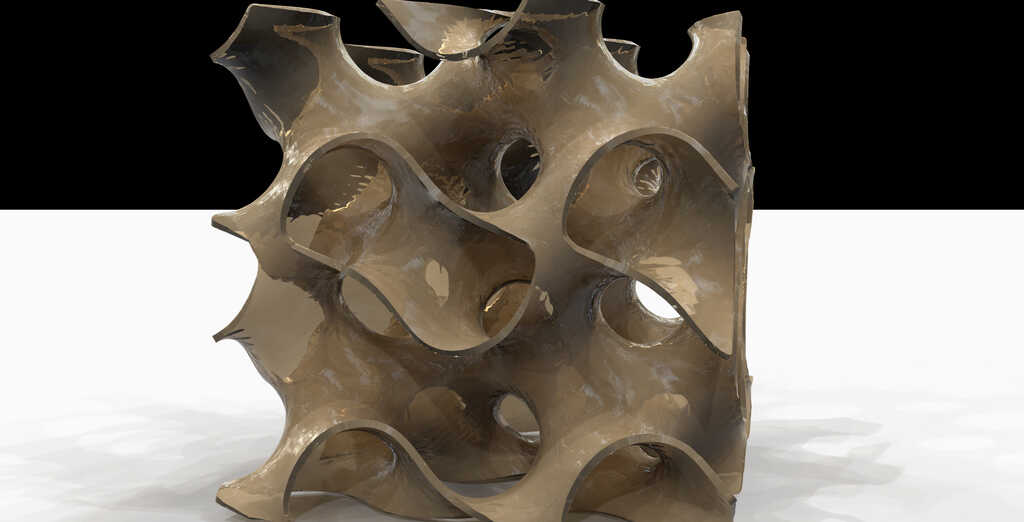
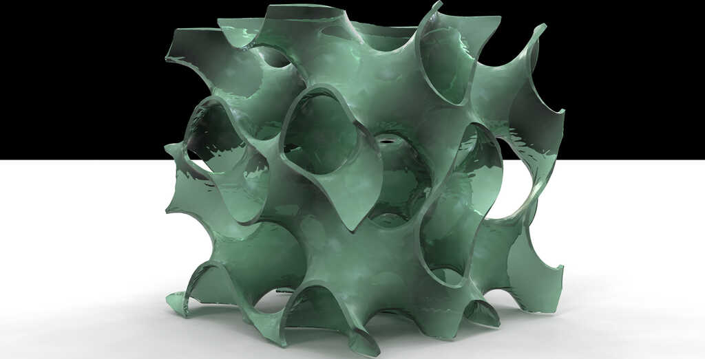
And here the .stl files.
Okayy, basicaly this part of the process is the more easy if everything work well with your 3D printer.
When you want to 3D print something you need to have an exchange type of file who can be readed by a software in order to convert it into a code lines. Each line of the resulting file is corresponding to a deplacement of the head of a 3D printer.
In my case I will use a .stl file and import it in a software called Cura. As I said this software take a 3D file and some parameters.
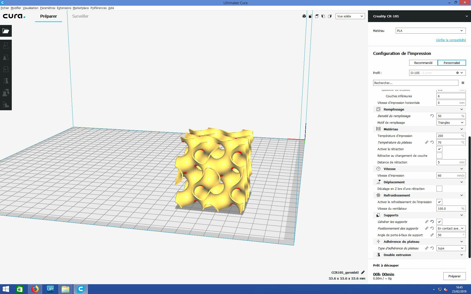
For this print the ultimaker was used then I decided to try on a chinese 3D printer, the CR-10 S This is a "cheap" 3D pinter but with really good opinion on forum ! Let's see the result !! But before we have to set-up the parameters. Below all of the parameters I have used.
I will just specify the part about support. As you can see on the first picture of cura there is some red zones. This zones represents the part with an angle superior of 50° with verical axe. This part are generaly hard to print without support, then I have decided to try to put some support beetwen the printboard and my model.
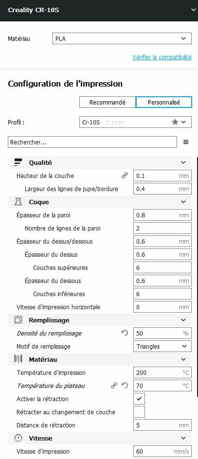
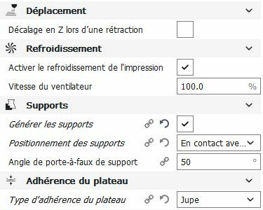
Okay, let's see the different parameters. The software that I use in my lab (Cura) is in french in order to facilitate the learning for the new people in the lab. I will not explain all of the different parameters but I will talk about the important paramaters in order to success a printing.
In the quality section we can chose the height and width of a line. In fact you can considere that is the "resolution" of the printing. In my case I chose an height of 0.1mm that means that a model with a height of 1 cm will be sliced into 10/0.1 = 1000 layers... Then the width is determined by the width of the nozzle, you can not chose a width inferior of the width of the nozzle. In my case the nozzle of the CR-10 measure 0.4mm.
I will not explain all of this part because most of the time those parameters doesn't change. They are depending of your machine and of the environment. Basicaly one of the thing very important in this part is that the plastic retract during the cooling. Then you have to test what is the best hull parameters in order to have a piece with the good measure.
This part is very important ! In the case of my piece there is no part to fill because this only a 3D surface. But most of the pieces that you will print will have some void parts. Then your slicer (Cura) need to fill those parts in order to solidify the piece and in order have a support for the superior parts. In a first you will chose the densisty of filling. This will inlflued the solidity of the piece, and the duration of the printing. Then you can chose the structure for the filling. Some of them are really strong but required more printing time. The best is to test !!
This part is depending of what plastic you will use, here you can see the parameters for the native orange PLA of the creality CR-10S
The speed depend of the material and the environment (temperature). In my lab the best that we have found is 60mm/s
This part of the parameters is one of the most important part ! In most the piece that you will print there is some zone in cantilevered. This zone need to be suported by something in order to have a good quality at the end of the printing. Basicaly your slicer is able to generate some supports. First you can chose if you want to add supports in any place of the piece that needs it. In my case I choose to put supports only on the zone that are in direct contact with the plate. I have made this choice because the shape of my piece is really complex and will not be able to remove the support everywhere. But if you use double extruding printer you can print the support with another plastic ! Specilally, the PVA is a plastic that is soluble in the water, then you can remove the support by putting your piece in the water. Unfortunatly, the CR-10 is only a simple extruding printer... Then in a second time you can chose the maximal angle where the piece doesn't need supports. In my case I choose 50 degrees.
Basicaly, all of the parameters that I talked are depending of you machine and of your environment (temperature). If you have some trouble to have good finish refer to forums and other documentation speaking about the same materials and machine !
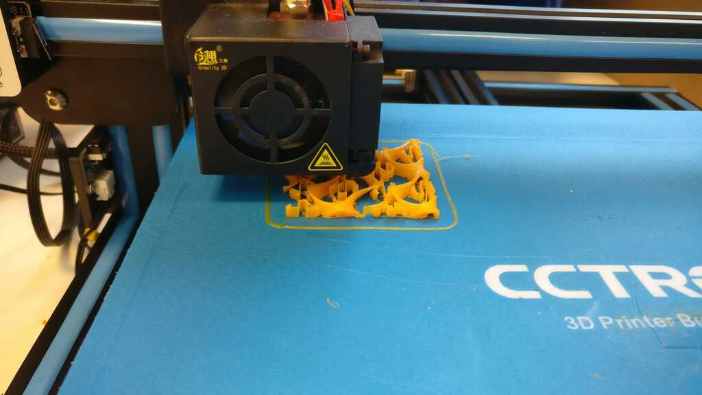
As you can see on this picture, we can see the start of the print, for now it's look good and we can see the support !
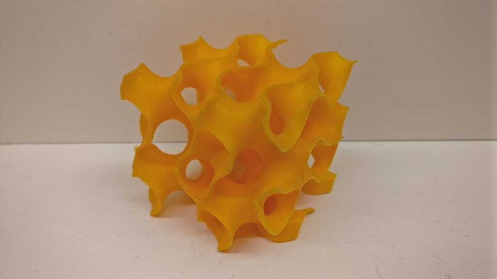
And finally, this the result !!! 6 hours and 13 minutes
I'm very happy and impressed of the quality of the impression for a 500$ printer. All of the part with the supports work well (as expected) but the superior part wich have no support are also very good, we can see some very little problem at this place but not a big deal.
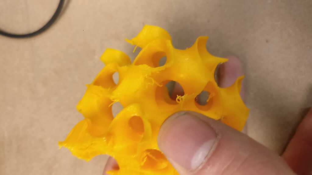
The final result is very impressive but we can still see some zone wih little pack of plastic, I think this is because of the quality of the printer and the time of print.
In a first time I will talk about the cons of the 3D printing. For me the biggest problem with this technology is the printing time. The plastic need to get colder in order that another layer could be printed, then there is a physical limitation using this kind of plastic.
But the 3D printing is still a very useful and powerful technology. One of the most powerful thing is the ability to print very complex pieces with a lot of fitting parts. The typical exemple of the sphere inside a cube, printed in 3D (during a unique printing) is a very representative exemple of the power of this technology.
grasshopper fileAll of the other file are downloadable through sketchfab because of there sizes :)
See you later space cowboy