
Project developement
--> Here the group assignement<--
Okayy, these week's assignements are quite imprecise but in the same time quite clear ! For this week our main tool is the CNC, a big machine wich able you to cut wood (or other materials) with the exact shape you want. The advantage is that you can remove matter in order to create connector with a lot of accuracy !
The CNC is tool that I know pretty well, then the challenge was for me to design something really basic but using with a lot of pertinence teh advantages of a 3 axes CNC.
As said in the title of this part in order to design something big I will use Rhino 6 But before I start drawing anything, I should have an idea of what I want create...
In a first time, I wanted to design a bass guitar but it was pretty complexe to get the good woods and other piece of a bass in the allotted. Then, a really good idea from Adel (my instructor) ! He told me to make a guitare stand, this idea immediatly inspired me and directly after the end of the Niel's course I started drawing...
Here I will not explain all of the processus of creation and how I found my idea of my design (even me I don't understand very well my own way of thinking) but basically, I have started by searching some guitar stands and after some test I get the idea to make a self-supporting structure !
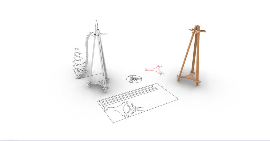
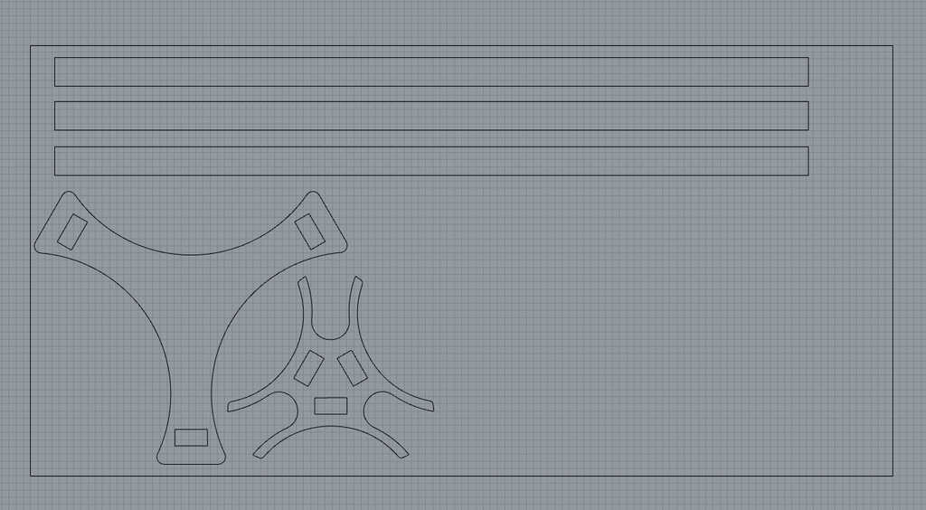
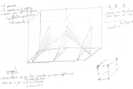
Here you can see my drawing table :
Okayy, now I will explain you how I have designed my object in order to usine it with a 3 axes CNC of 1200mm X 600mm.
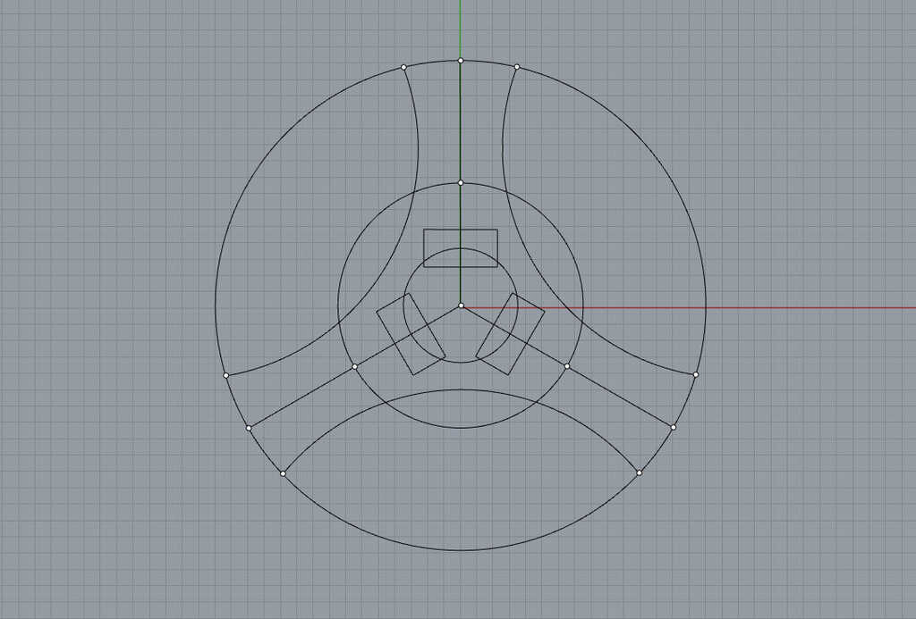
First, I have design the shape of my superior part, which will support the guitares. To do this I have principaly used the circle tool and some basic geometry ;)
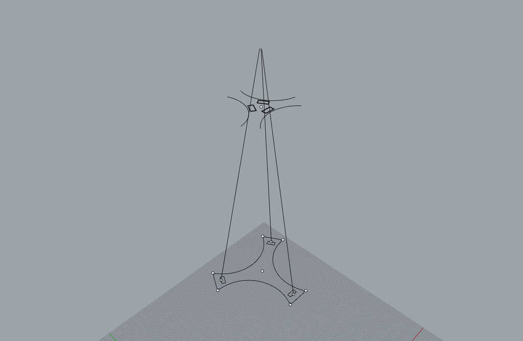
Then on the same method I have designed the inferior part and linked the two parts with lines. This lines allow me to have an idea of the angle for rod parts ! Anf then I am able to estimate the offset beetwen male and female parts. In my case with the angle I wanted to have I choose an offset of 5mm. Be careful, this offset is really big and adapted to create an angle beetwen the parts that must fit together. In a other case, for perpendicular embedding I should use an offset of 0,9mm
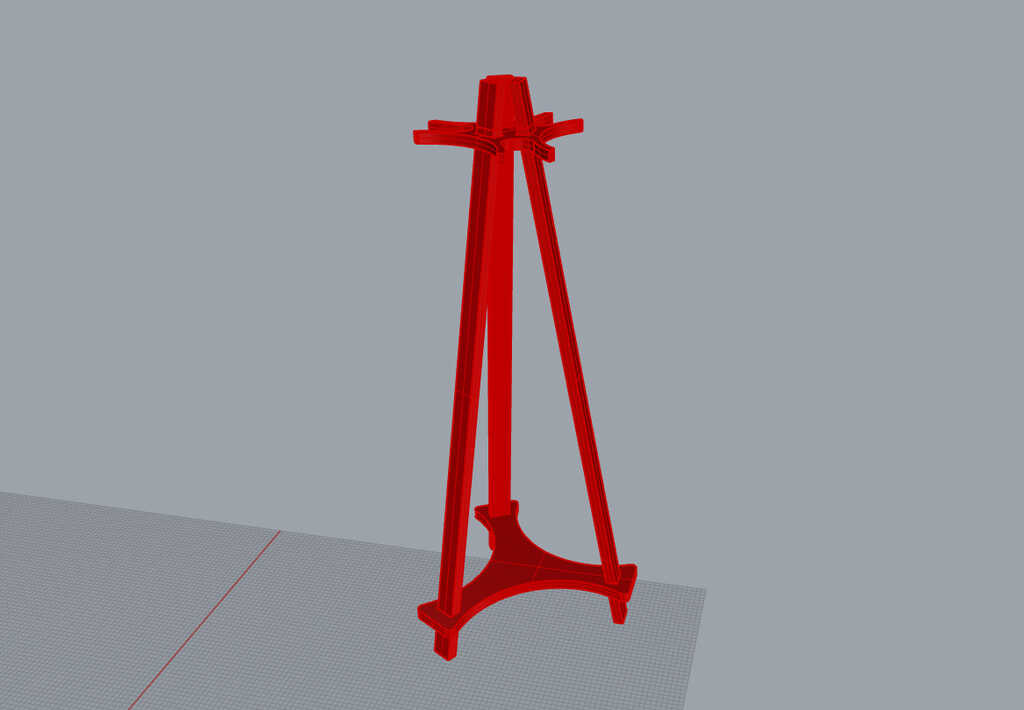
Basically after that, I have created some plane surfaces and then extruded them... This the result :
Now I get all of the parts off my design and I must prepare them for the export to Vcarve pro.
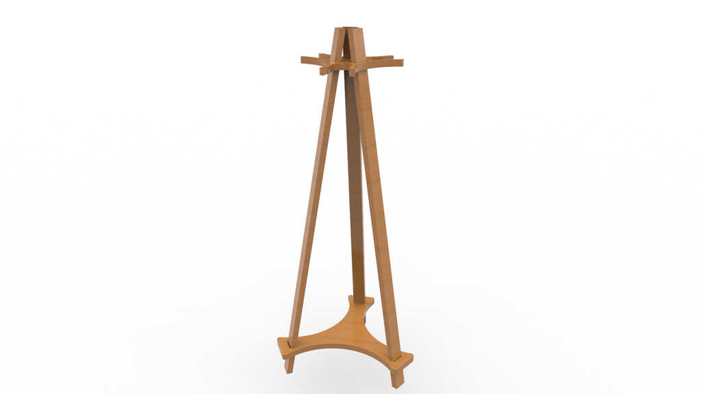
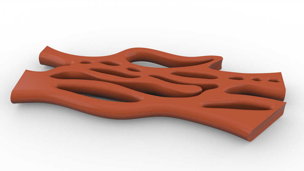
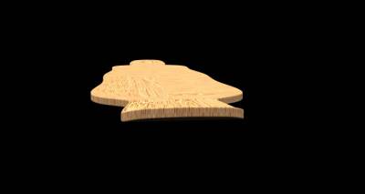
But before to start the machining, a little render what it should look like :D
Basically a CNC a router is a mill put on router. The router is able to move into different axes. Most of the machine are 3 axes. A CNC router is very similar in concept to a CNC milling machine. Instead of routing by hand, tool paths are controlled via computer numerical control. The CNC router is one of many kinds of tools that have CNC variants.
This part is pretty simple, in it we just have to import the 2D file and create the toolpaths.
To do this, first click on file and select import drawing and import your files. For some reason you should modify it with the scale function and maybe rotate it ! When it's done and the drawing is well placed in your material let's start to create the toolpath !
To do this, open the right panel with all of the differents toolpath possible. In a first time we will create the interior toolpath (the holes in the top and bottom parts). Then select them countour and let's click on the countour toolpath in the right panel !
There is a lot of thing in this panel but basicaly we just have to choose our bit and edit it parameters. Then choose the good machining strategy ! In my case I will use a one tooth straight bit of 1/4"... This is the parameters I use :
| Diameter | Depth | Step-over | Spindle speed | Feedrate | Plunge speed |
|---|---|---|---|---|---|
| 6,35mm | 3,17mm | 40% | 6000tr/min | 40mm/s | 30mm/s |
The choice of this parameters are explained in the caracterisation part (group assignment). But basically there is some things to know.
The spindle speed and the feed rate will depend of the diameter and the number of tooth.
Depending of the diameter of the mill, the radial speed will change. If you have a big diameter the radial speed at the level of the tooth will be big. Then big mill need to feed speeder than small mill.
Depending of the number of tooth you will need to go feeder or not, basically a mill with two teeth will need to make only one half turn (180 degree) to remove the same quantity of material that a mill with one tooth in a complete turn (360 degree).
Then you will need to go feeder for a mill with more teeth.
Then about the feed of the mill it will depend a lot of the material more it will be soft, more you will be able to go fast in it.
But there is also a directly factor to the feed. If the speed is really big and the feed is really slow, you will create a lot of friction at the sames points and it will create heat. Then your material risk to burn and your mill will be damaged.
At the inverse, if you have a too high feedrate and a low speed you will destroy the material and damaged the mill.
Basically, there is some formula to calculate all of this parameters but most of the time they are ofr metal and not wood. Then this is a lot of experimentation, experiences and by reading the advise of the mill that you buy !
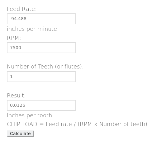
The chip load is a measurement of the thickness of material removed by each cutting edge during a cut. This is a valuable piece of information that can then be used to calculate new set ups. Calculation are as follows: Chip Load = Feed Rate (inches per minute) / (RPM x number of flutes). Chip loads are based on material thickness of average size for cutting edge length of tool.
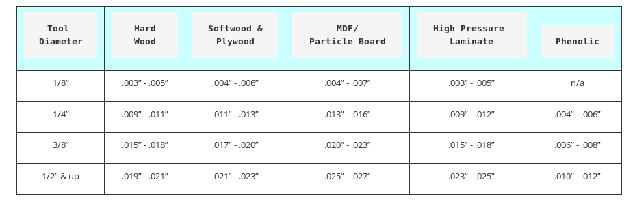
As we can see on this table, we can see that the chipload for my mill (1/4") and the plywood is about 0.11"-0.13". Now let's verify if my parameters are good with a chipload calculator.
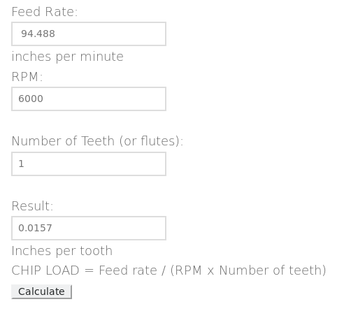
This is my first calcul using the first parameters that I use for my machining. Basically, I get a chipload about 0.015" this mean that I need to have a speed rotation bigger or a feedrate slower.
As you can see, in order to reach the chipload that I needed I hav modify the spindle speed !
I didn't had the time to test this change during this week (I discovered the chipload after this week) but at the end of the Fabacademy I tested to find out the feed and speed with this chipload calculator. I helped Adel to mill some hardwood and the result was really great !
After editing the parameters of the bit I just modify the machining strategy in order to machine within the lines. Else, my holes will be bigger than expected...
I have repeated the same method for the outlines but choosing a machining strategy outside of the lines !
And finally add some lugs in order to hold the and disable them to move with the force of the bit...
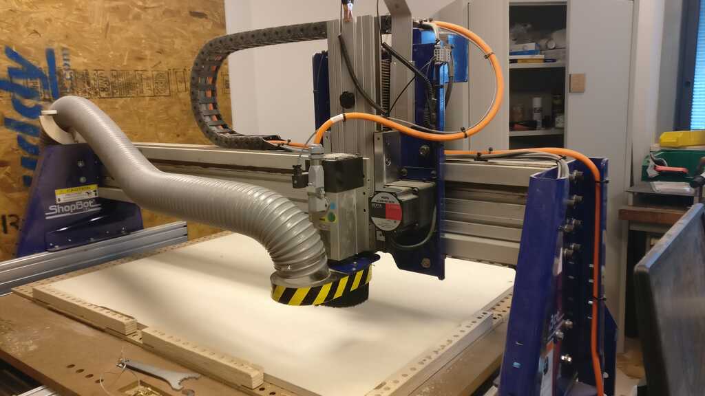
Now let's prepare the CNC for the machining.
This the differents step in order to have a ready to work CNC :
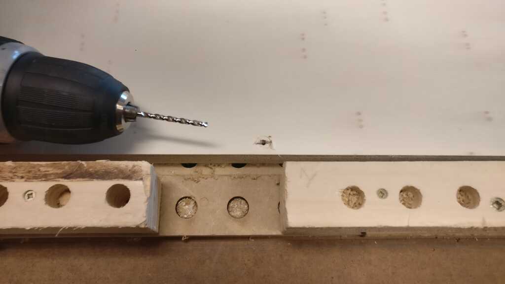
In order to fix the board, I start by making some little hole at the futur places of my screws in order to do not splinter the wood.
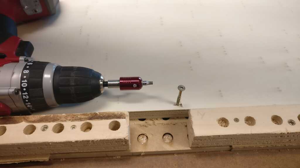
Then I put 6 screws, 4 at each corners and 2 beetwen each corner (lengthwise)...
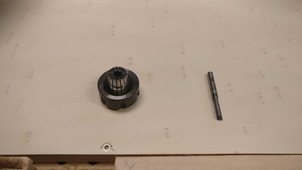
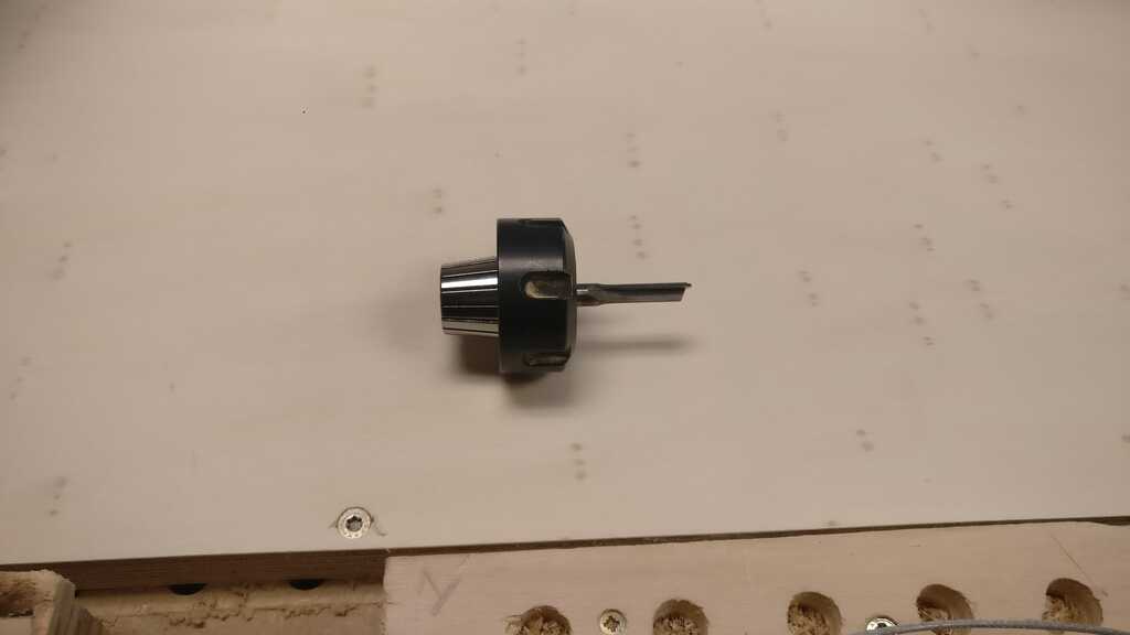
Now I prepared the bit and collets :

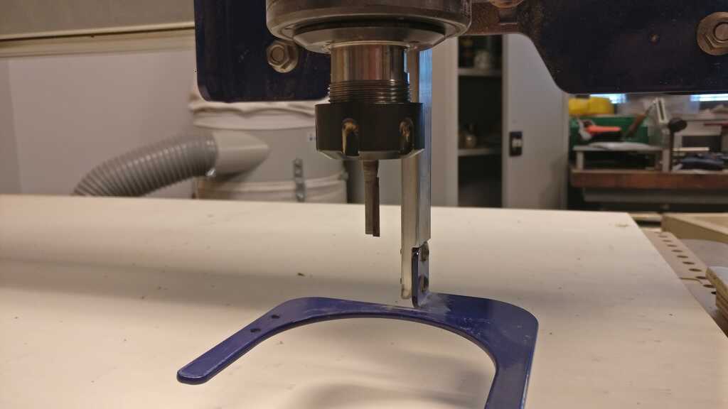
Fixe it to the router :
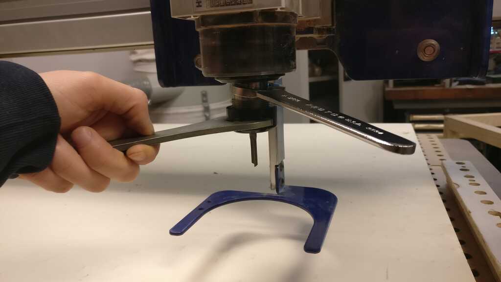
And I squeeze it :
Almost everything is prepared, the last thing is to set he zero coordonates.
To do this I use the Shopbot menu, in it I open the control panel clicking on the yellow icon.
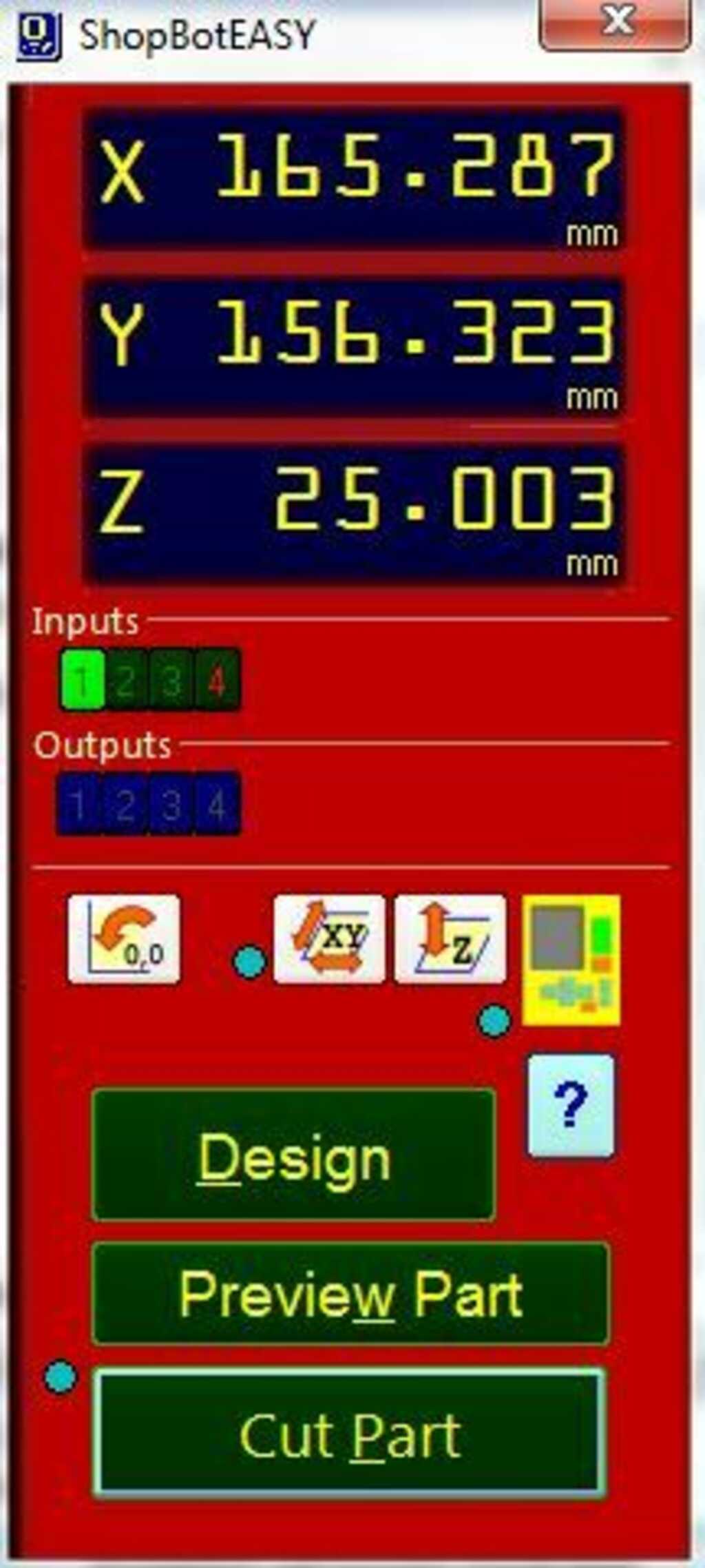
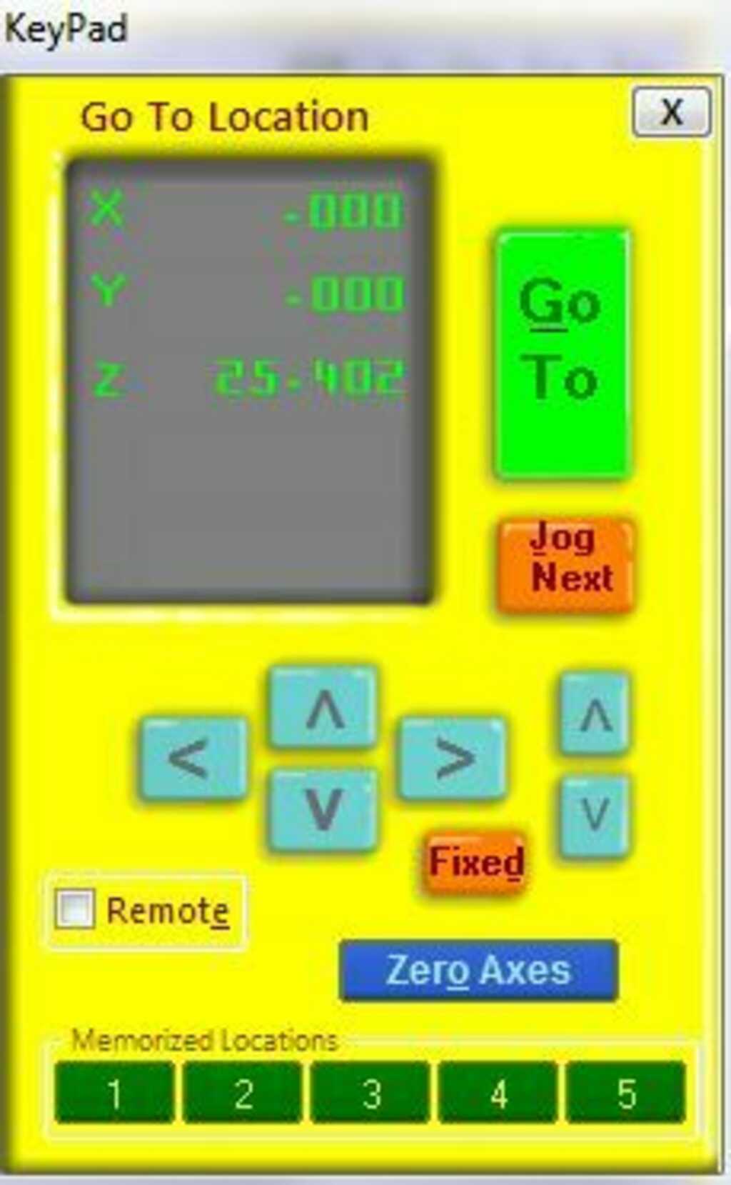
I move the bit in the bottom-left corner, outside the area with the screws !
And i click on zero axes and check the X/Y cases
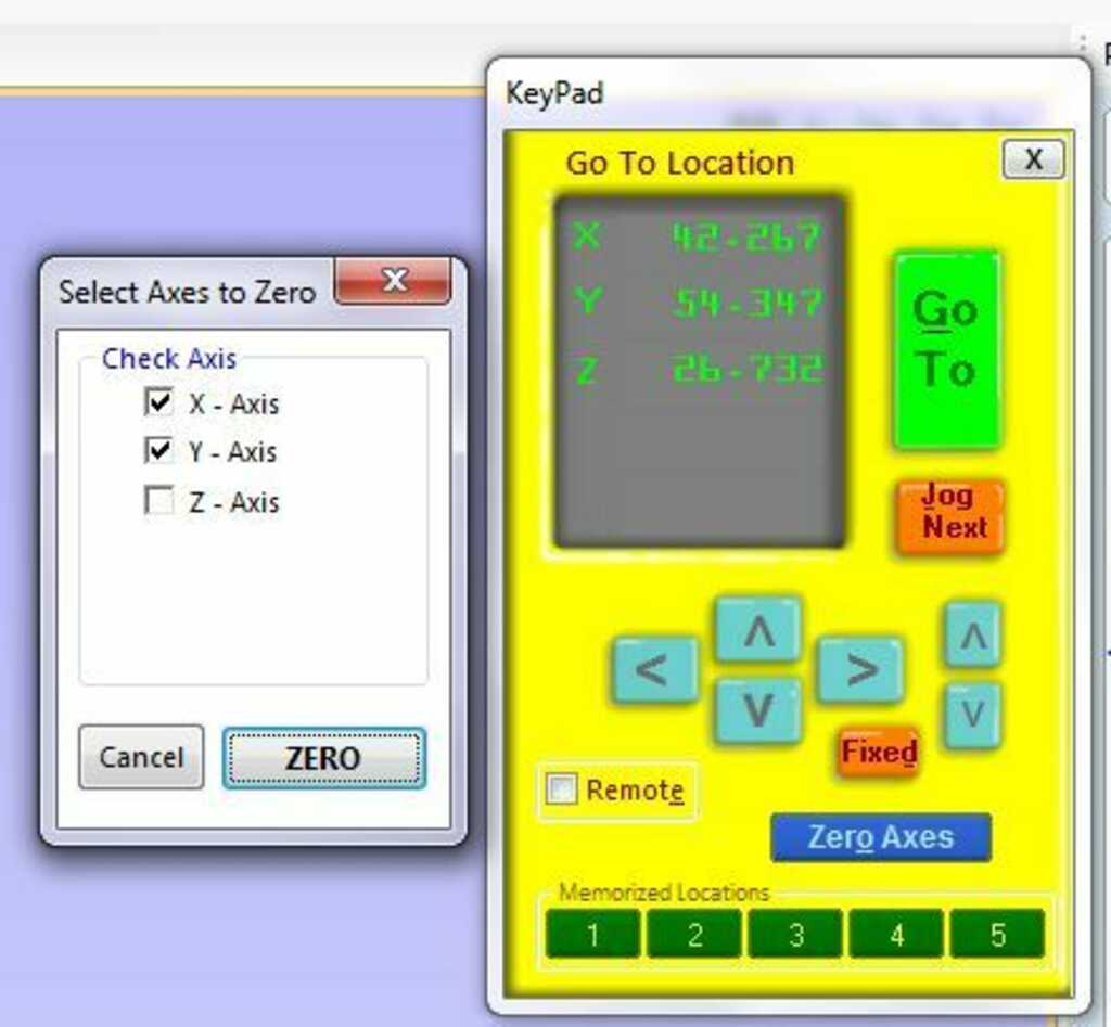
In order to make the Z zero, there is a little function that reconize when a contact is made beetwen a plate and the bit. Then place the alligator clip on the little grey part above the ventilation pipe. Then place the plate under the bit and click in the red shopbot panel on the Z button. It should do something like this :
And finally the CNC is ready to work. I launch the machining and let's see the result.
After some deconnection of the CNC during the machining, I must restart to machine some parts because the machine lost it X/Y zero coordonates... In order to provide other deconnection I have double check the connection and I have cleaned up the computer (full of dust)...
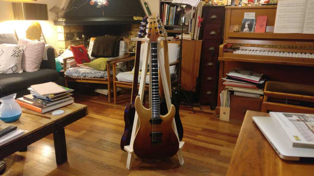
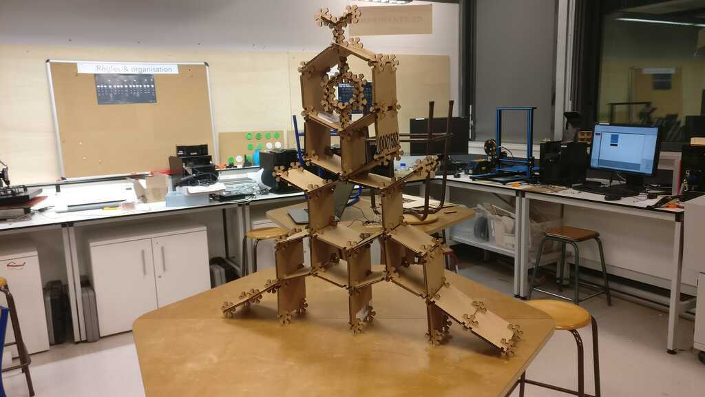
And this the result !!

Im very happy because it works !! There is no glue, screws or nail the structure is supporting the the weight of the guitares perfectly !
For this week I didn't learn a lot of thing... The CNC is my predilection machine and I have started to frequent fablabs by using a CNC in order to create a longboard press. In ly Fablab I'm in charge of the CNC formation for the people who want to use it.
But in this week I have tried a new type structure... The object that I have made is self-supporting structure. This type of structure plays a lot with the offset beetwen the differents parts. In fact in them the parts need to be moving in order to create an exchange of direction of the effort. This allow your object to stand up. I guess I can improve my construction by making more test with differents offset.
Project developement
Intelectual property
Wildcard Week
Machine design
Interface

Mechanical Design
Networking and communications

Application and Implication
Output device
Input device
Molding and casting
Embedded programming
Computer-Controlled Machining
Electronics design
3D scanning and printing
Electronic production
Computer controlled cutting
Computer-aided design

Versioning and Website
Idea of my final project
How to modelise a longboard
For any suggestion, help or featured project