
Project developement
Embedded programming, thats mean that I need to code something and put the "instruction" to an electronic device !
Then I need a IDE (integrated development environment). In it I will be able to type the code in different languages and add some plugins.
I'm using Visual studio code because of all of these functionalities that it provide ! Natively, there is git interface that allow you to manage your git files. But you can also add some plugins, in this part I will use platformIO (but you can install into other IDE like Atom), plateforIO is a very powerful tool for IoT development. That allow you to build code for different type of processor or microcontroler, and upload the code into them using a lot of different frameworks or upload protocols. With it you can create your own build and upload process but there is already some really good process that I will use in order to program an ATTINY44 with differents ISP programmer.
I have installed it directly in Vcode through the extension menu. When its done you can start a new pletformIO project ! In the src folder that will be created I put my C code, and now I will configure the plateforIO configuration file called platformIO.ini.
In a first time I will use an arduino as ISP. And all of the different configurations are here Then I will use the arduino as isp configuration.
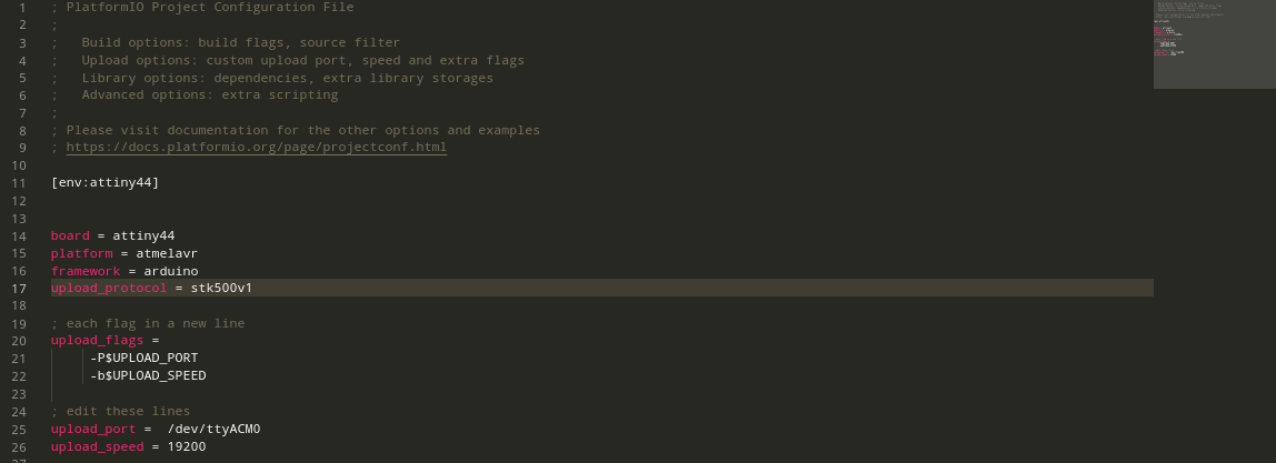
Now lets plug the hello board to the arduino with the ISP connection. On the arduino I will use the MISO, MOSI, SCK, VCC, GND and RST pins.
When the board is plugged I use the keyboard shortcuts : CTRL+ALT+U. This command will execute all of the building and upload process !
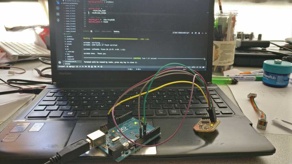
And it works pretty well, the operation is a sucess and my led is blinking !
Now let's try to upload the same code with the famous FabISP of the electronic production week !!
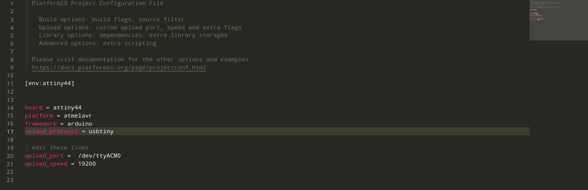
In a first time we all get (every fabacademy students of the lab) different error when we tried to use it. In fact, the FabISP was properly detected by our computer as a TINY USB, but when we have tried to use it with differents way and differents OS always get an error... initialization error rc = -1 or bad device signature.
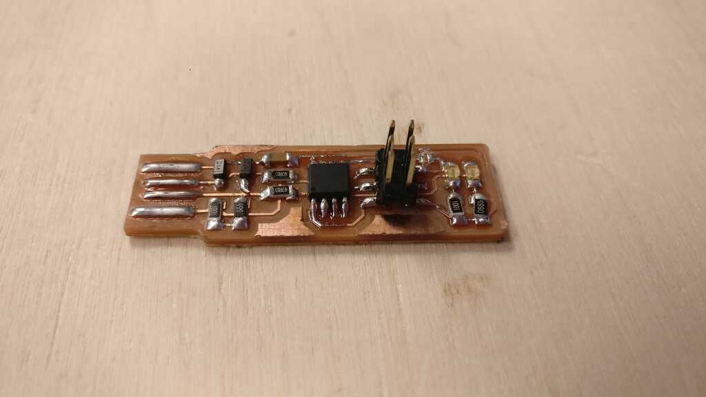
After a lot of researches, Adel find out the problem !! When you want to program your board with the FabISP you need to power the board from two way : through the ISP connect and also through the FTDI connector. But be careful the two different GND must be linked !
Here this is the setup :
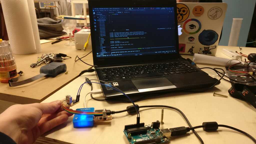
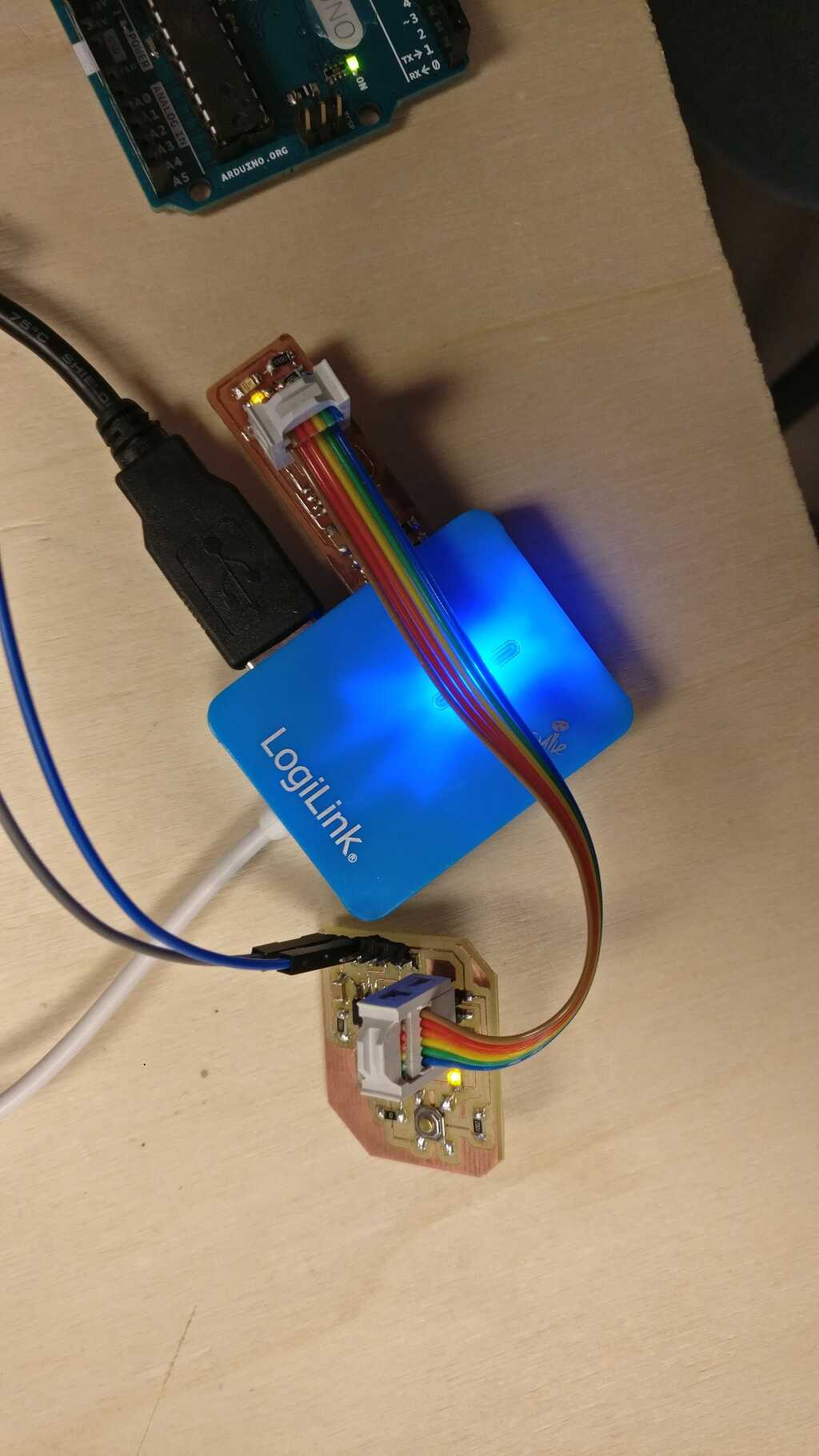
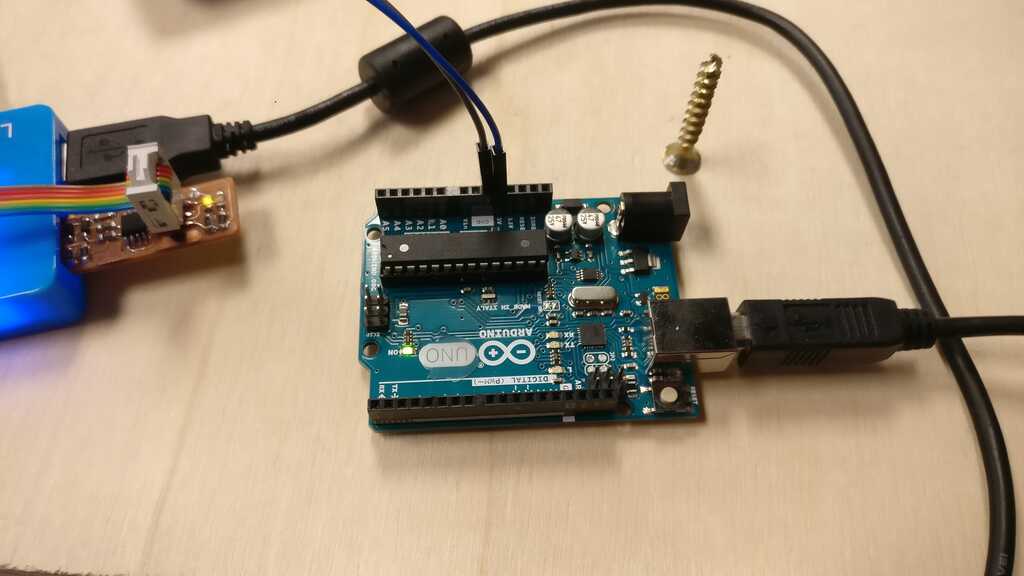
As you can see I have used an arduino to be the second power source, and I have used the VCC and GND pin of it plug into the VCC and GND pin of my FTDI connector ! But the two device are connected to the same USB hub in order to link the two GND ! And its working pretty well !!
In this section I will explain how I have programed a nodemcu 32s board based on a microcontroler ESP8266 and using microPython !
The first that I have made is to install the esptool package. I have used pacman -S esptool. For OSX, windows or another Linux distribution you should check the way to install it.
When this is made I can now communicate with the board.
I have connected the board and my computer using a serial FTDI connection USB. At this state wha I want is to re-write the flash memory with the microPython firmware.
First I have to erase the flash. To do this I use esptool with this command : esptool --port /dev/ttyACM0 erase_flash
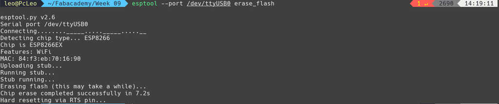
At first I get an error Failed to connect to Espressif device Invalid head of packet (0x00)
In order to provide this, execute the command and then you have to hold on the GPIO0 button during a reset.
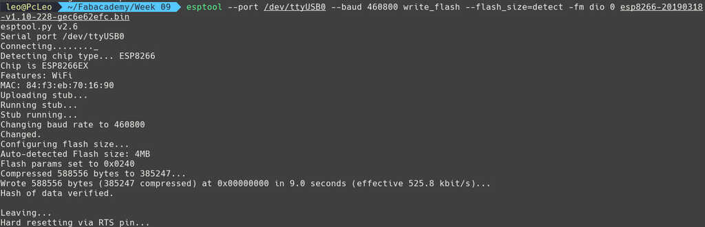
I have to flash the new microPython firmware. This firmware will interpret microPython codes put directly on the boards or through a REPL (Read–eval–print loop, also termed an interactive toplevel or language shell) I downloaded it from microPython download page and i took the last stable firmware for the ESP8266.
Now lI have tried to flash the esp8266 with this command : esptool --port /dev/ttyUSB0 --baud 460800 write_flash --flash_size=detect 0 [firmware location]
If you get an error it may be because of you OS architecure (some linux or mac OS) you can use this command : esptool --port /dev/ttyUSB0 --baud 460800 write_flash --flash_size=detect -fm dio 0 [firmware location].
Okayy now I can start an REPL in order to try some basics intruction.
To do this, I downloaded picocom with pacman -S picocom. But you can do the same with a software like screen or any other
type of software that served as a low-tech serial communications program to allow access to all types of devices that provide serial consoles.
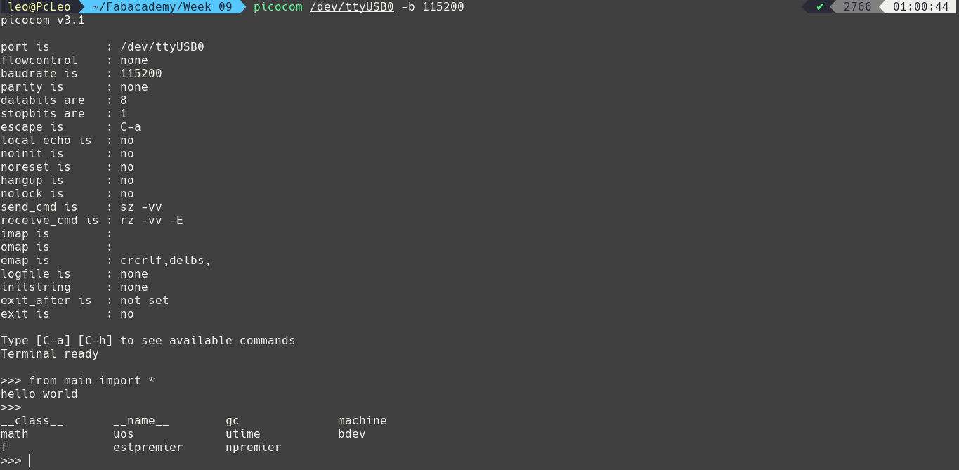
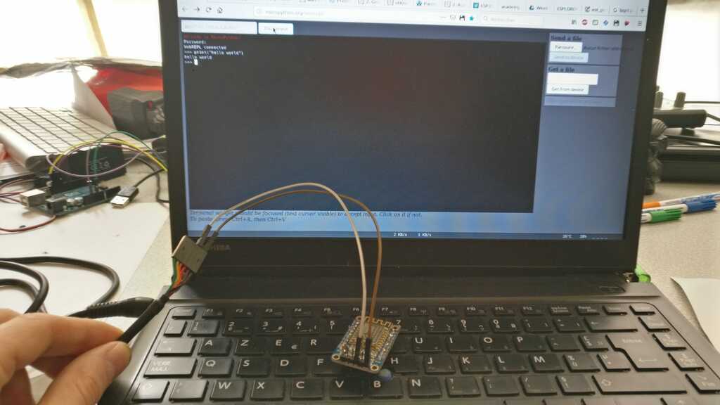
Then I used this command : picocom /dev/ttyUSB0 -b 115200 . A REPL is then loaded I can make first a "hello world" !!

But let's try to put directly some code into the board. To this I need a tool to put the code in the board, I have choosed Ampy a Adafruit MicroPython Tool - Utility to interact with a CircuitPython or MicroPython board over a serial connection. But you can use other software like rshell (from dhylands) or webrepl (from paul & damien) (I will use webrepl in a second time ;) )
In order to install it have cloned the git repo with git clone https://github.com/pycampers/ampy . And in the repo I installed it with python3 setup.py install.
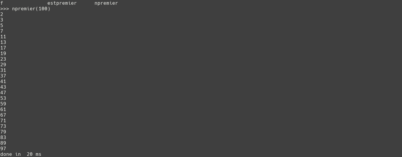
I have coded a little script that found all of the prime numbers beetwen two limits, let's put it on the board with ampy -p /dev/ttyUSB0 put main.py

If you get no error, that mean that the transfer was made properly ! But you can verify it.
Let's launch a REPL using the same previous picocom command. And then use import uos and then uos.listdir()
You should see something like this.

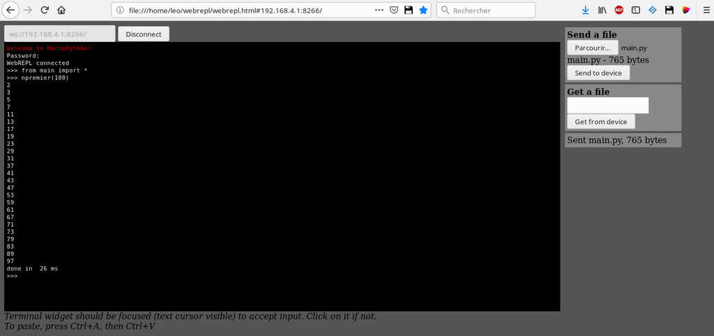
In my main.py file there is some functions, let's import it ! To do this I use this command from main import *
And then I can call my function that will calculate all of the prime numbers beetwen 0 and 100.
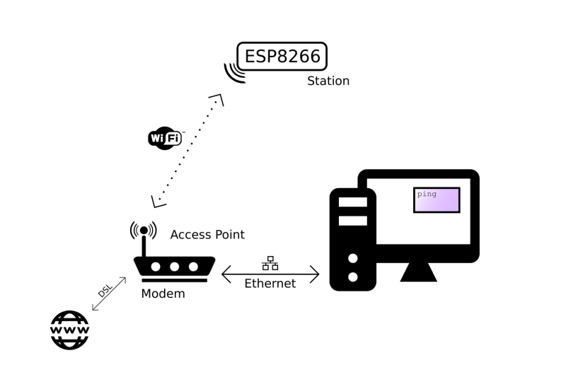
As I said earlier, instead of using picocom in order to communicate with your esp8266 through a serial connection, you can use webrepl and communicate wwith your esp8266 through a wifi connexion.
The esp8266 can turn on as a wifi hotspot. The method is to connect your computer (or other device) to it, then the webrepl is a webpage .html using python scripts and java scripts.
You can download it here or directly go on the microPython website who hosts a webrepl http://micropython.org/webrepl/ . But before you can connect you must turn on the wifi of the ESP8266.
To do this, launch a repl with picocom and in it use import webrepl_setup. Then you just have to follow the configuration instructions.
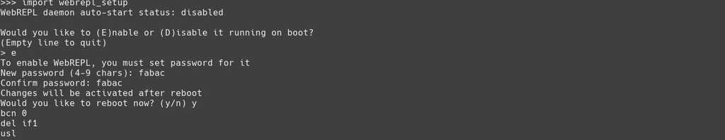
After the webrepl configuration the board must reboot. After that Im now able to connect my computer to the esp8266 wifi.
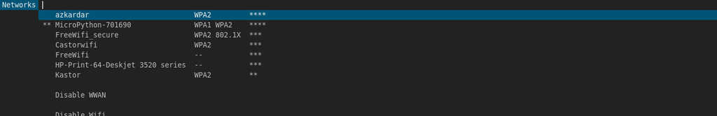
In my network mange I chose MicroPython-XXXXXX. The password is a generic password : micropythoN.
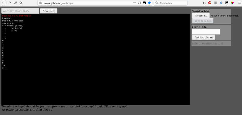
Now I am connected to the board, I launch the webrepl page with firefox webrepl.html. And I can unplug the serial connection, I just let the GND and VCC pin connected in order to power the board.
Okayy let's try to type a little loop instruction !
And with the same method, that I have explained previously, you can upload a .py file in the esp8266 and then use the different function of it !
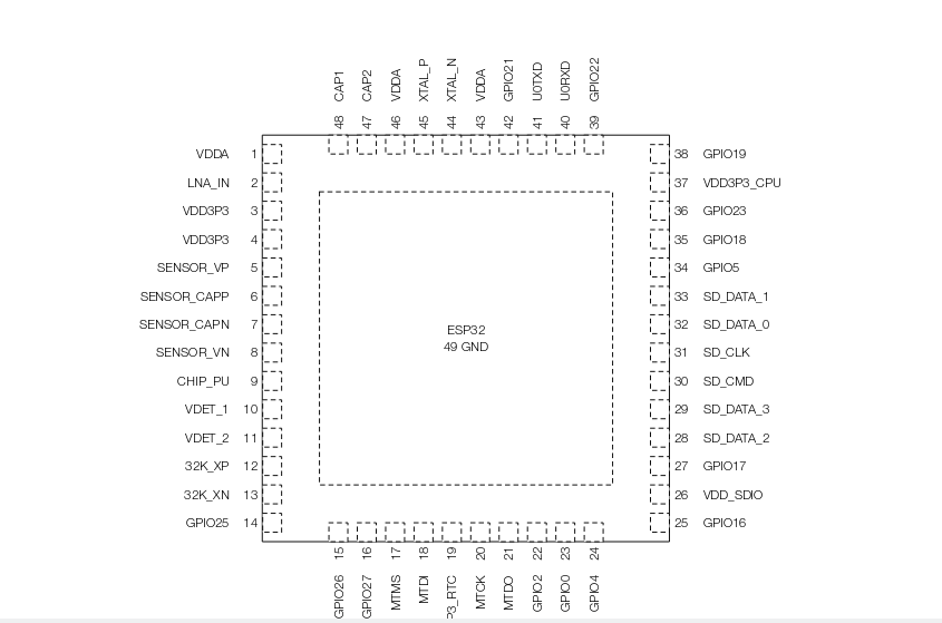
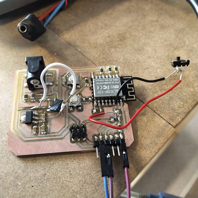
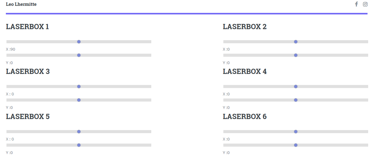
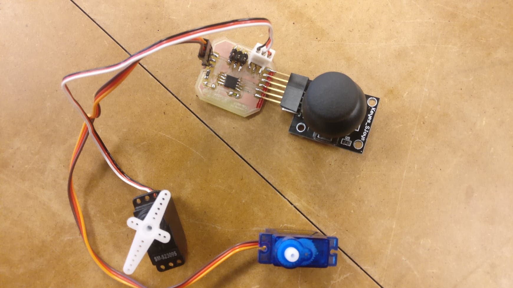
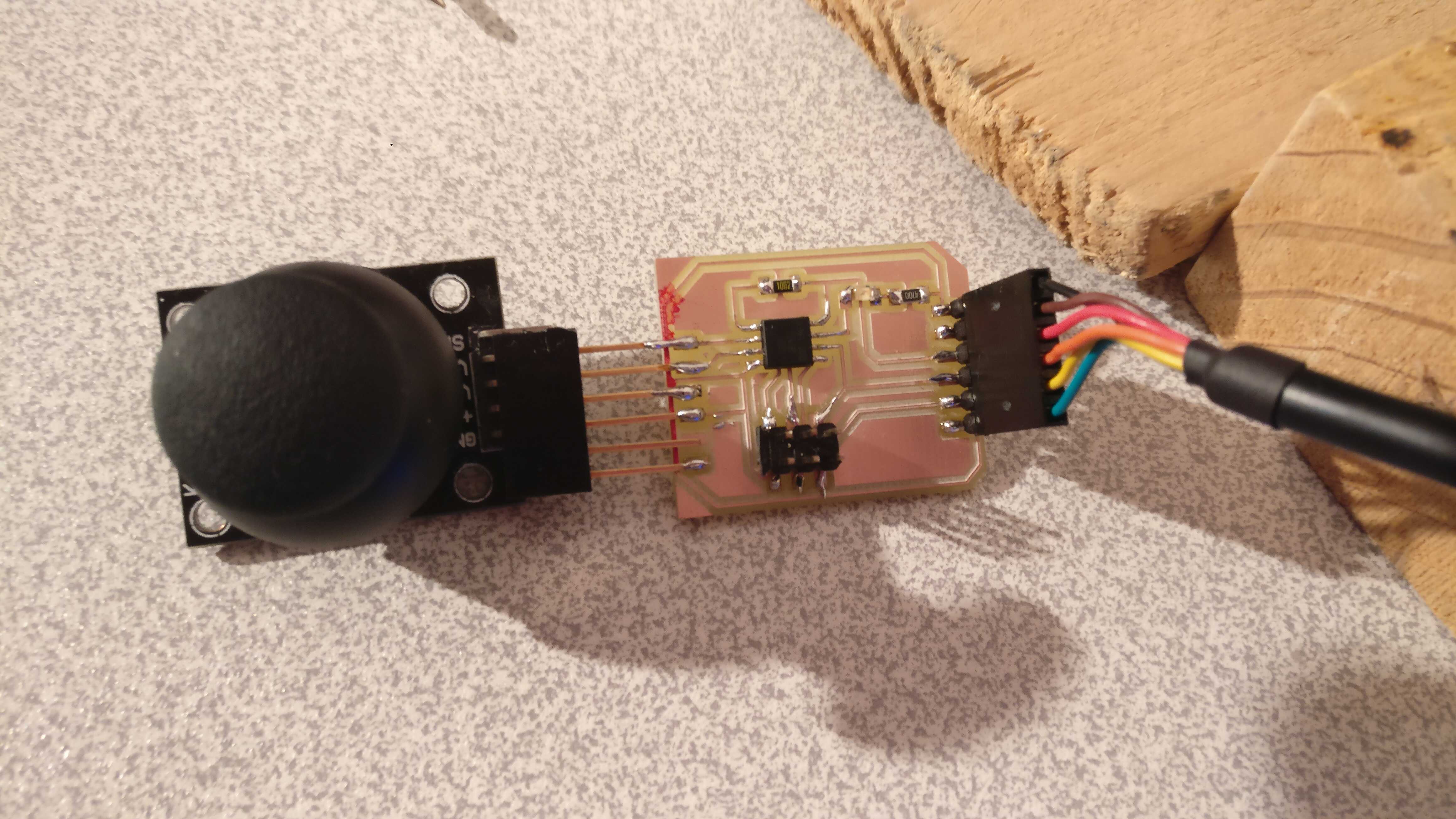
For my final project I want to use a little network of board controlling servo-motors in order to move lasers... To do this I want to use some ESP32 because they have a wifi connection ! Then I need to create my own esp32 based dev board. Let's read the datasheet of the esp32 !
In it we can learn that the esp32 must be powered in 3,3V. And many others informations about the differents pin, type of memory and many more things...
Basically when you are on the first page of the Datasheet you can read the details of all the features available on the esp32.
Basically, this is most of the features that I will use. There is also a lot of bluetooth features but I will not detailled this here because I won't use them.
 Basically there is :
In the datasheet it's explain that the choice of the differents modes passes by the strapping pins.

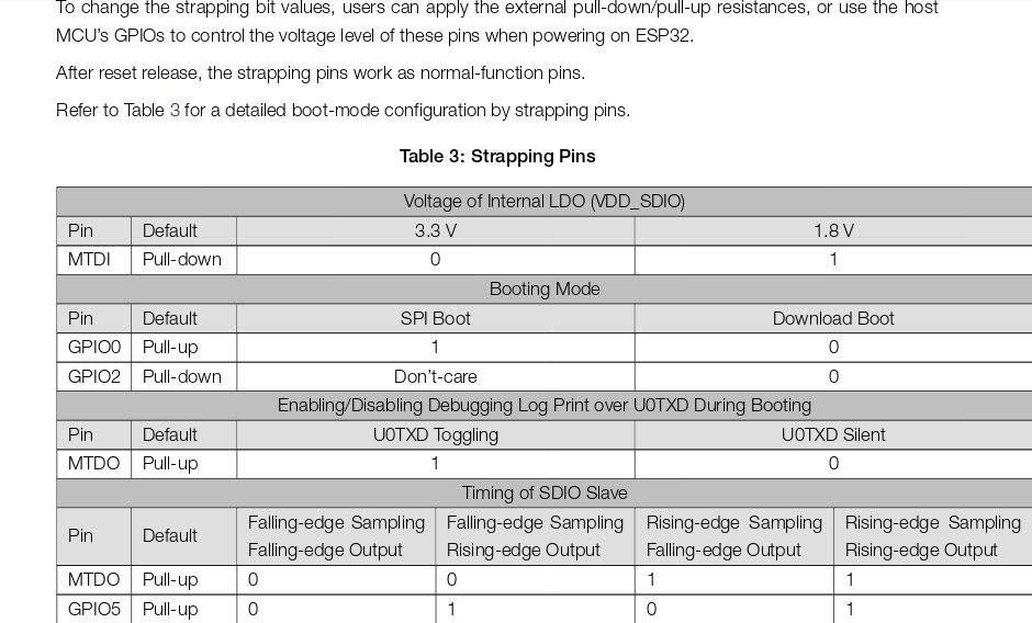
Then it's explained that we need to switch the states of differents pins from 1 to 0 or from 0 to 1 in order to switch modes.
For exemple if I want to put the board into the SPI boot mode I need to put the GPIO0 pin into 1.
In the last week I had the time to familiarize myself with ATMEL microcontrolers, how they work and how we program it. They are very cheap and very powerful for a lot uses. But I have principaly learned how works esp microcontrolers with microPython. MicroPython is programation language very pleasant. The syntaxe is really supple, and the memory operation are in my sens more readable and digestible.
I'm eager to do more experimentation with this type of microcontroller !
Project developement
Intelectual property
Wildcard Week
Machine design
Interface

Mechanical Design
Networking and communications

Application and Implication
Output device
Input device

Molding and casting
Embedded programming

Computer-Controlled Machining
Electronics design
3D scanning and printing
Electronic production
Computer controlled cutting
Computer-aided design

Versioning and Website
Idea of my final project

How to modelise a longboard
For any suggestion, help or featured project