
week 3: computer-controlled cutting
week 4: electronics production
week 5: 3D scanning & printing
week 8: computer-controlled machining
week 13: networking & communications
week 14: interface & application programming
week 15: applications & implications
week 16: mechanical design & machine design
This week is about playing with programming languages to display, for example, the data from the input device made in week 10. My input device was a magnetic field sensor (actually, a pair of them), and I plan to use Processing to display the readings using the convention for magnetic fields directed into/out of the plane of a drawing - namely dots for a field coming out of the plane, and X's for a field going into the plane. I would like to make a grid of either X's or dots (determined by the sign of the field) that will change color to correspond to the strength of the field. To that end, I've been working my way through several Processing tutorials to get a feel for it.
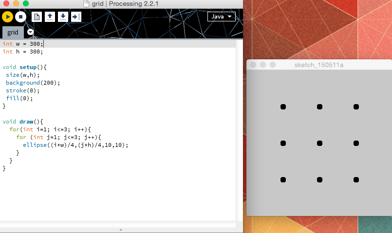
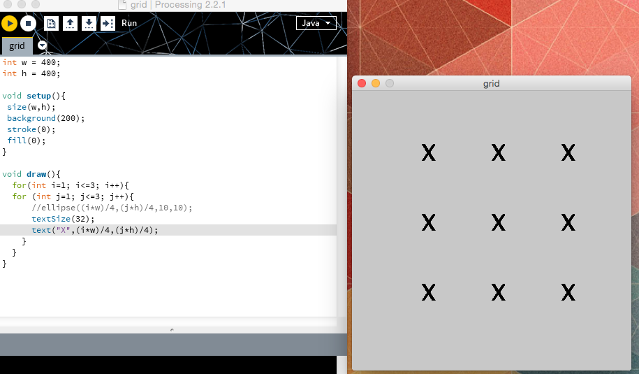
My first step was to write a simple program to create a grid of either small ellipses or text X's.
The next step was to try to get that grid's type (dots or X's) and color to be determined by the data from the Hall effect sensors. My first attempt at that involved running the B_field_board Arduino code from week 10 to write the output of the Hall effect sensors to the serial port (which worked), and simultaneously run the Processing code to read from the serial port and use those readings to color the X's on the grid (which did not work).
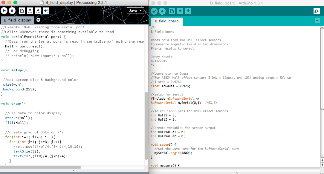
This didn't really surprise me; I figured both programs couldn't be using the serial port at the same time. For the second try, I referred to the Processing sketch in the tutorials and modified that code for the display I wanted. I think it's doing essentially the same thing, but not running both the Arduino program and the Processing program at the same time.
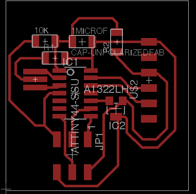
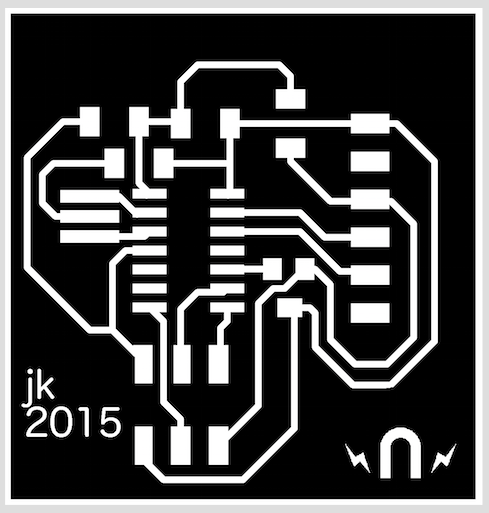
Unfortunately, while testing, I attached the FTDI cable a bit too forcefully and pulled the header off the board, along with its traces.
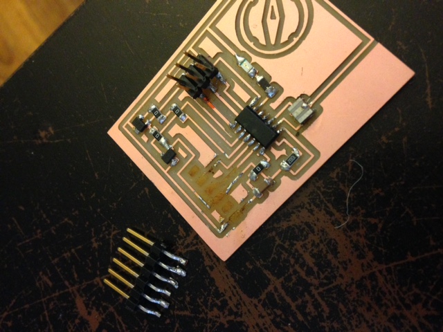
I redid the board, this time with only one Hall effect sensor.
The test of the new board with the Processing sketch was pretty cool - I got the dots or X's to appear and change as a magnet was moved around the sensor. It's got a few bugs still to sort out, however. I used the sensor's readings to calibrate the Processing sketch's display (when it should switch from dots to X's, etc.), but that could use some fine-tuning. The display is also currently just grayscale, getting darker or lighter in response to the magnet. I need to play a bit more with the way Processing describes color to get the display I originally imagined.
Jenny Kostka Fab Academy 2015
