
week 3: computer-controlled cutting
week 4: electronics production
week 5: 3D scanning & printing
week 8: computer-controlled machining
week 13: networking & communications
week 14: interface & application programming
week 15: applications & implications
week 16: mechanical design & machine design
This week I think I will be able to use for my final project (yay!). We are building circuits with output devices, and my final project will need at least one type of those. Specifically, in my final project I'd like to use an LCD output to act as a countdown clock for a spacecraft approaching a target, so this week I planned to practice building and programming the LCD display.
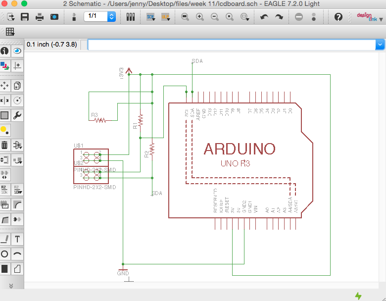
The original approach I wanted to use was to connect last week's project to this week's project by building a small breakout board with the LCD (actually an OLED) display. This could then be connected to my input board and display the readings from the Hall effect sensors. I wasn't able to do this, though, with the OLED we had, because it uses I2C protocol to communicate, and I didn't have pins available on the input board to connect it. Because I want the OLED (or an LCD) to be part of my final project, I still wanted to use it, so Shawn suggested making a shield for the Arduino board (which has the SCL and SDA pins needed for I2C).
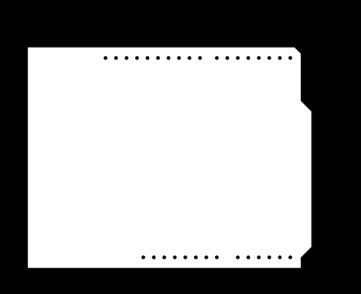
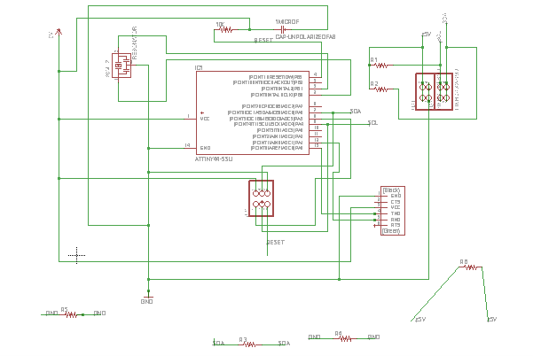
I downloaded the adafruit EAGLE library to get the Arduino outline part, and used two 2x2 headers to match up with the placement of the OLED's pins. The rest of the board was pretty simple.
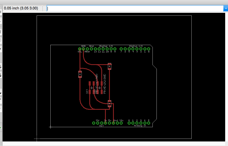
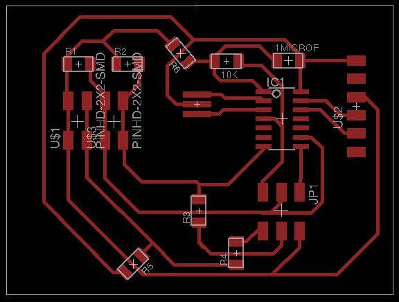
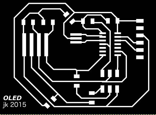
In The GIMP, I combined the traces for the two 2x2 headers to make them neater, and added a little bit of text/design.
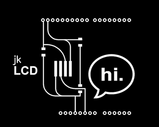
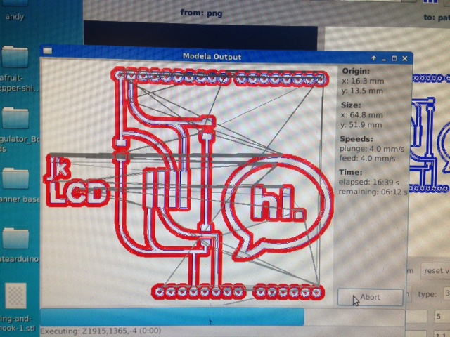
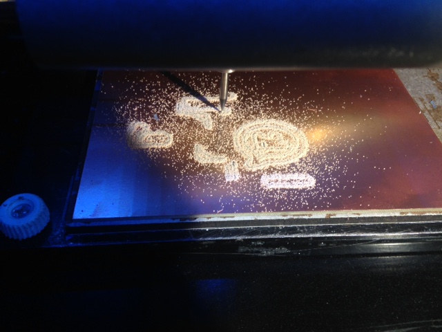
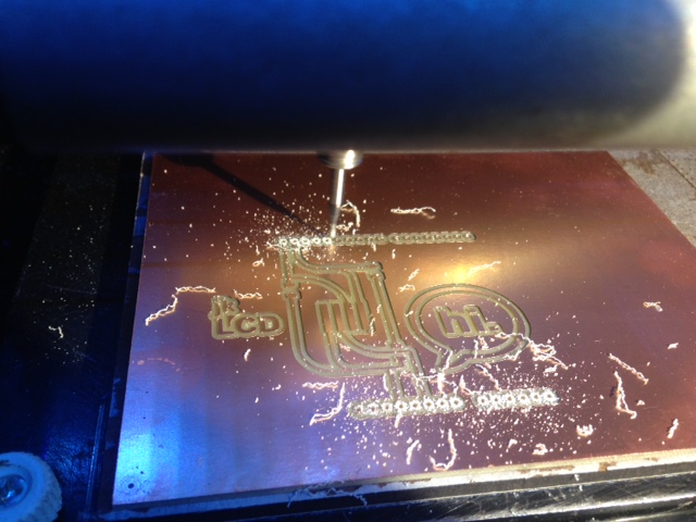
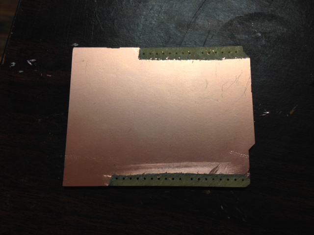
I milled the board with the Modela, and I made a couple of mistakes here. One was to mill the board from FR1 that had copper on both sides. This meant that the through-hole pins would short, so I had to use an exacto knife to scrape away the copper around the holes on the back of the board. I also milled the board before I realized that the component I'm using is an OLED, not an LCD, so the engraving on the front is wrong. This is annoying, but it didn't seem like a big enough deal to redesign and mill a new board.
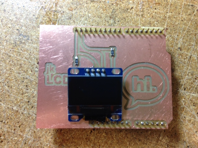
Finally I soldered the components. I had to bend the pins on the OLED so that it could be used as a surface-mount part, which was a little tricky because of the third mistake I made. I had placed the OLED at the center of my board, and I guess I didn't quite realize how big it is, because I had to bend the pins underneath so that the OLED wouldn't block the holes for the Arduino's pin layout. This made soldering tricky, but not impossible.
Programming the board is a work in progress. I started by researching I2C, and I found some useful explanations and Arduino libraries to get me started, namely sparkfun's, adafruit's, and Oscar Liang's. I'm still working on reading through the code and figuring out some questions - for example, I feel like I have a good handle on what the adafruit code is doing, but it uses a reset pin on the OLED, which mine doesn't have. And Oscar Liang's libraries seem like they will work, but they're a bit more opaque; I can't really tell what's going on. Ultimately I'll write the code and program the board myself, but I'm still figuring out how to do that.
After Wednesday's review, I realized that I should just make a whole new board instead of making a breakout board or an Arduino shield (which I wouldn't have done for the final project, honest!). So I designed a self-contained board, based on the hello board, with the OLED.
I didn't end up making the redesigned OLED board from this week; instead, a version of the board was used in my final project. In that project, I made a few changes to the board: I used an ATMega because I needed more memory, and I added a voltage regulator. I tested it with several programs from the u8glib library, as well as programming it with the code to display the Mars Curiosity headlines.
Jenny Kostka Fab Academy 2015
