
week 3: computer-controlled cutting
week 4: electronics production
week 5: 3D scanning & printing
week 8: computer-controlled machining
week 13: networking & communications
week 14: interface & application programming
week 15: applications & implications
week 16: mechanical design & machine design
This week we are back to working on electronics, making input devices. My final project requires input, but from a website, not a sensor. So I won't really be able to use this assignment for my final project; I'll have to wait until communications week.
So for this week, I decided to make a magnetic field detector, but with a slight difference from the sample that will hopefully make it easier to use as a compass. Instead of a single Hall effect sensor, I'm using two, arranged at right angles to each other. That way I can get the magnetic field strength in two dimensions and be able to determine the direction. Even if the sensitivity isn't enough to detect Earth's magnetic field very well, I can always use it in physics labs with my students.
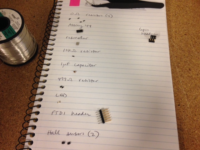
I started with my hello board from week 6, and replaced the button with the two Hall sensors.
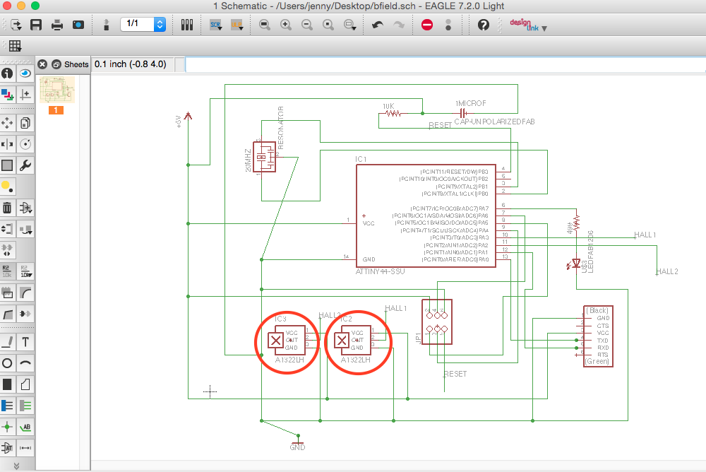
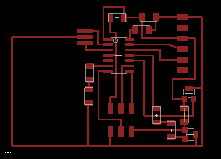
I also moved things around a bit and redid all the traces, to hopefully have an easier time milling and soldering than I did with the hello board.
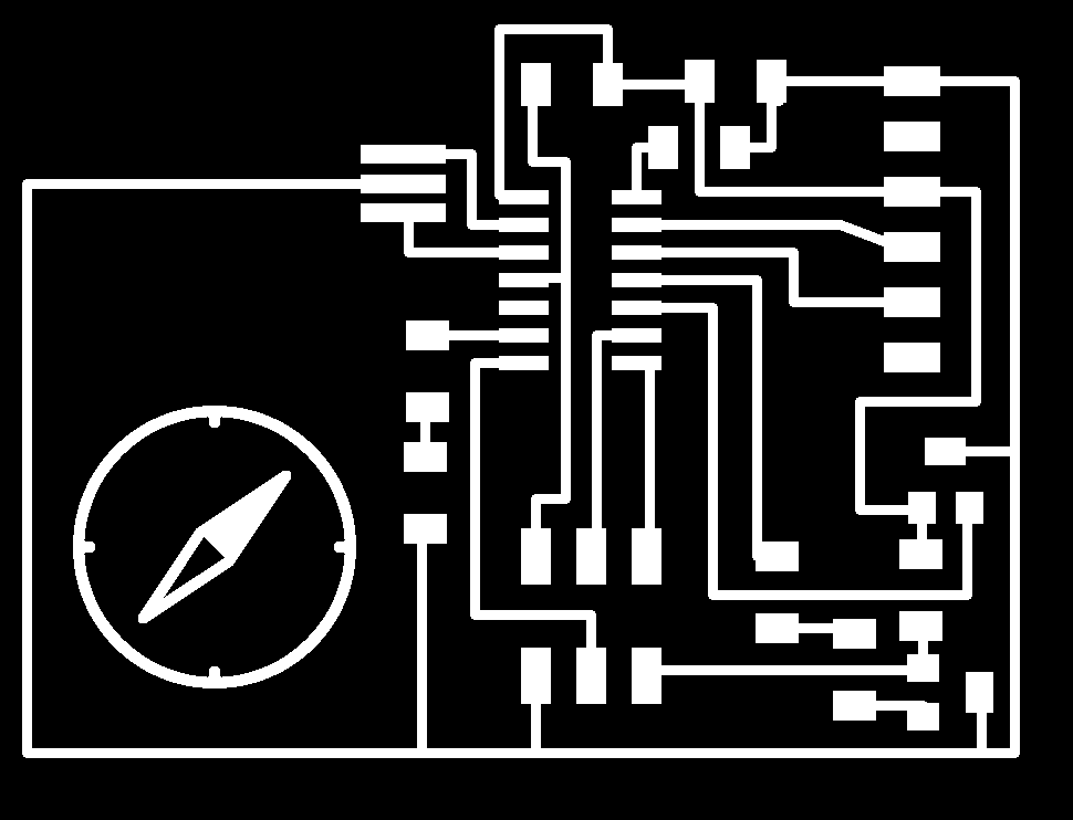
Finally, I used The GIMP to make the traces and the outline, adding a compass icon.
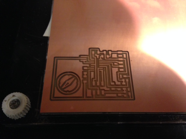
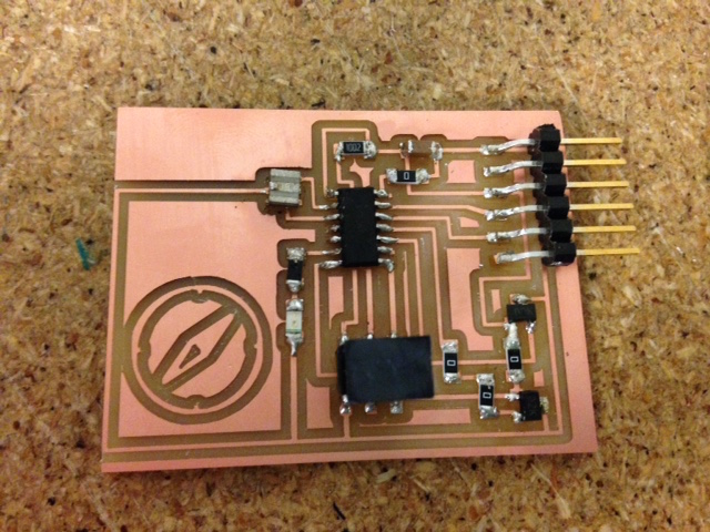
As predicted, milling and stuffing the board goes much more smoothly now. The completed board was able to be programmed on the first try, with no troubleshooting necessary (a first for me!).


The next step was to write the program that would allow the board to function as a compass. I started by looking at Arduino examples that read analog input and that print using the serial port. I took elements of each of them to write a program that reads the input from the two Hall effect sensors and prints it to the serial port.
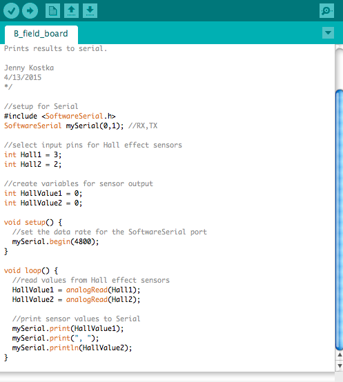
The program did just what it was supposed to do: it displayed the reading from the Hall effect sensors to the serial port, reading 509-510 for each sensor. Moving the board around and turning it upside down caused the reading to change, but not very much. Bringing a magnet close to either sensor had a much more dramatic result.
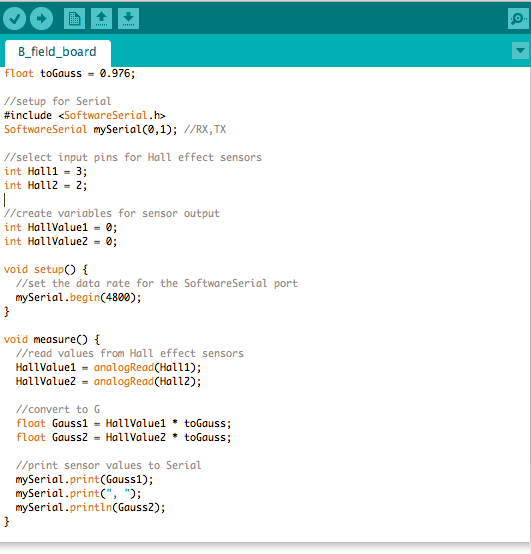
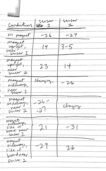
Unfortunately, the idea for using the sensors as a compass isn't working out quite as planned. After looking at the data sheet and other people's work with Hall effect sensors and Arduino, I did make some updates to my program, the most important of which was to convert the reading to Gauss. After that, without any magnets near, I got readings of -26G. The Arduino program I looked at was using the Hall effect sensors to measure the fields of magnets, so it included code to subtract that base reading off. This wouldn't work for me, though, because the data I want is somewhere in that -26G.
The idea to use the perpendicular orientation of the Hall effect sensors to get the direction of magnetic fields is also problematic. I took some rough data using a magnet, and while the readings varied with the distance and the orientation of the magnet, the orientation of the sensor didn't seem to matter.
The good news is that all the steps to creating a board with a sensor went smoothly: designing the board in EAGLE, milling, stuffing, and programming. The board and its sensors are working just as they should. I just need to figure out how to get them to give me the kind of data I want - if they can.
Jenny Kostka Fab Academy 2015
