
week 3: computer-controlled cutting
week 4: electronics production
week 5: 3D scanning & printing
week 8: computer-controlled machining
week 13: networking & communications
week 14: interface & application programming
week 15: applications & implications
week 16: mechanical design & machine design
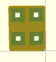
There are two different designs I've been thinking about for the housing for my project. The wall-hanging design consists of two parts: the poster-sized wooden base with cutouts for various pieces, and the plaques with the images of the different spacecraft on them.
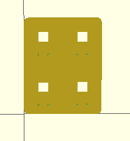
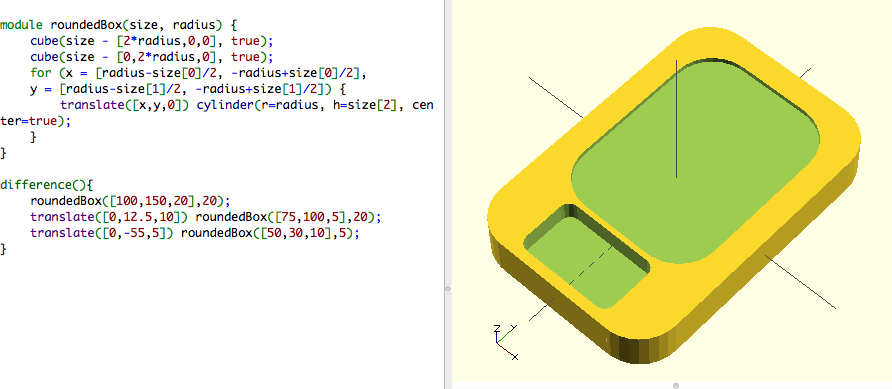
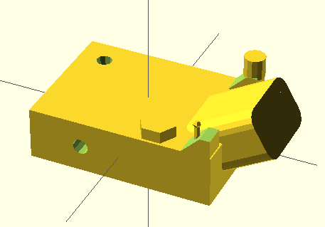
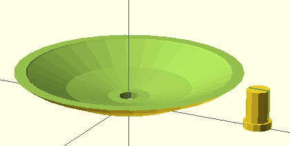
I modeled the base in OpenSCAD, because that's the 3D design program I've come to feel the most comfortable using. It is essentially a 1m x 80cm square with rounded corners, with pockets cut into it for the plaques. The pockets also have an opening that goes all the way through, where the circuit boards will live. Lastly, there are holes that cut into the back and go almost all the way through, where the LEDs will go. This way the front will look completely smooth when the LED is off, and the light will shine through it when the LED is on. The pictures show both the front and back view of the base.
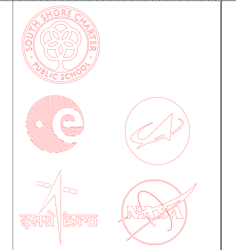
As the plaques will be lasercut and engraved, I modeled them in Inkscape. I chose four spacecraft to be the initial ones that will be followed: Curiosity, Juno, the ISS, and New Horizons. I found the simplest drawings of them I could to use for the plaques.
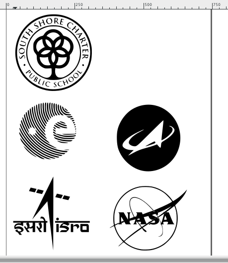
Lastly, in the center of the base I will include vinyl-cut stickers of the logos of various space programs, as well as the school's logo. These I also modeled in Inkscape.
In the interest of spiral design, I also modeled a single-plaque version in OpenSCAD.
I've started my thinking about how to make my project functional by researching RSS. I know my project will be pulling from the websites of the different spacecraft being tracked, and RSS seems like the most efficient way to do that.
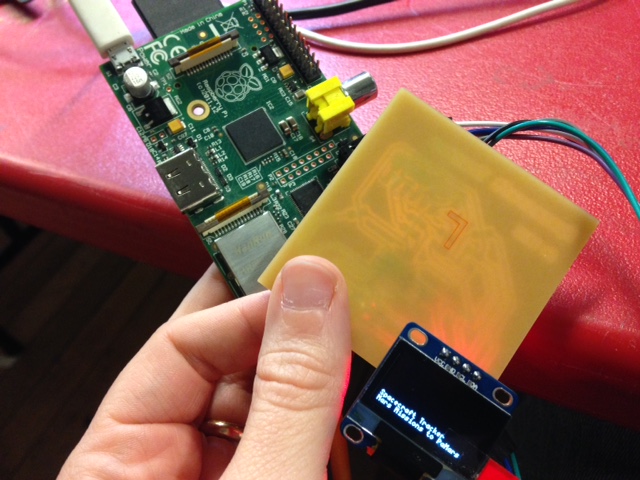
For accessing and displaying that data, I'll be using a Raspberry Pi as a hub, connected to individual OLED-screen boards for each spacecraft. The first one will, I think, be the ISS, specifically tracking when it is overhead (in Norwell, MA) and displaying a "Look up!" message.
The first tasks were to get both the Raspberry Pi and one OLED board up and running. For the Raspberry Pi, I downloaded the Raspbian OS to an SD card and booted up the Pi. I also set it up to control it via my laptop and SSH, and to share my Mac's Wifi with it. Unfortunately, it seems I couldn't do both at the same time - when the Pi's Ethernet cable was plugged in to my router, I could access it via SSH, and when it was plugged into my laptop and sharing the Wifi, I could only use it with a different monitor, keyboard, etc. A little bit of research found that other people have had this problem, but I couldn't find a solution.
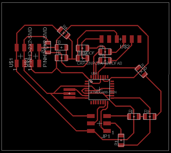
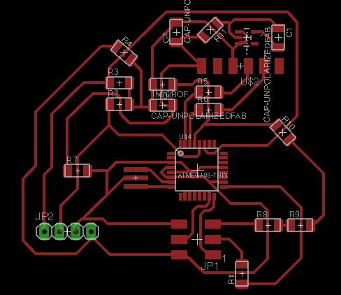
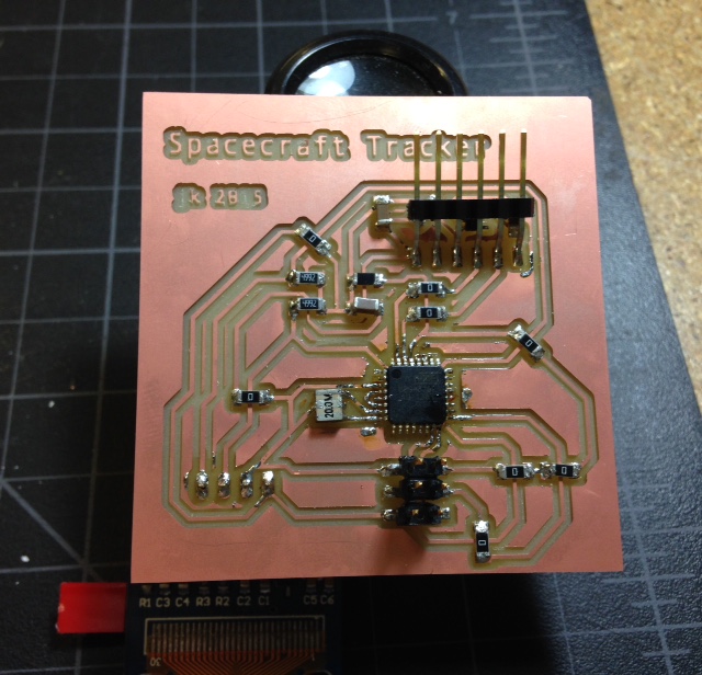
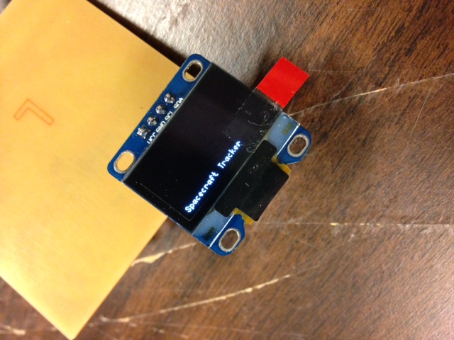
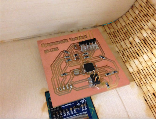
The OLED board proved similarly frustrating this week. In week 11 I made an Arduino-shield version of it, and this week I made a board from scratch with an ATtiny. I've had a couple of problems with it, though. First of all, all but the simplest sketches I've tried (mostly examples from the Ug8lib library) have been too large for the ATtiny, so I've designed (but not yet made) a new board with a bigger microprocessor (pictured below). More importantly, though, while the board is able to be programmed without throwing any errors, nothing shows up on the display screen. I'm still working on troubleshooting, trying to figure out if the problem is something to do with the I2C communication or the screen itself.
End-of-the-school-year/Commencement/machine-building stuff all limited the amount of time I had this week. I didn't really get any farther on the electronics, though I did work on the project's housing design.
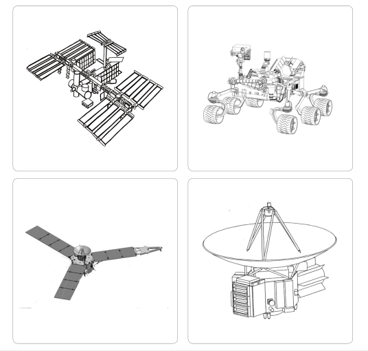
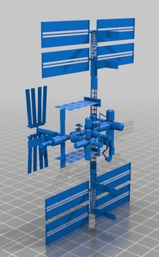
The second housing design consists of a laser-cut base with 3D printed replicas of spacecraft on top. I like this design better, but I'm still pretty new at 3D design, so I was very happy when I found design files on Thingiverse of several of the spacecraft I would like to track, such as these of Curiosity and the ISS:
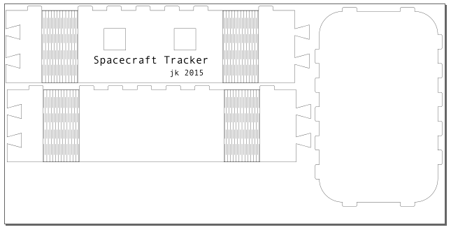
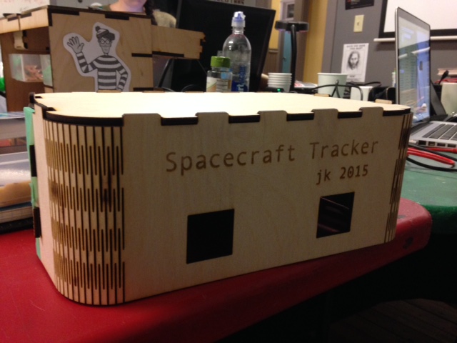
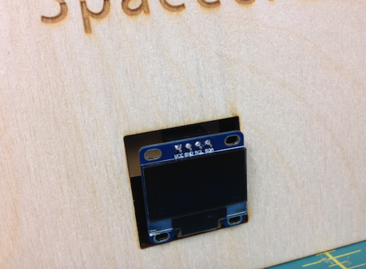
I started modeling the base in Inkscape. It's a pretty simple rounded rectangle, a little bigger than 10cm x 20cm (those are the dimensions of the straight parts of the sides). The circuit boards will go on the inside, with the OLED screens coming through the holes in the base. The top is one flat piece, and the sides are constructed of two pieces with living hinges for the corners.
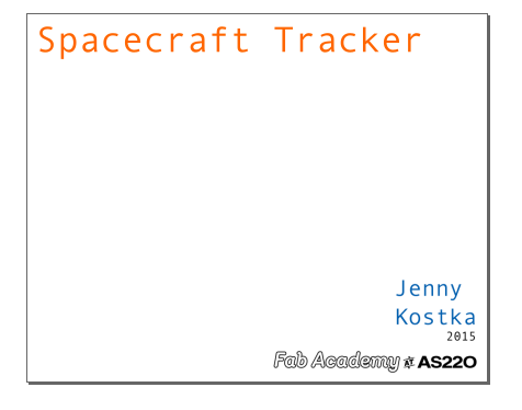
I also set up an outline of the final presentation slide.
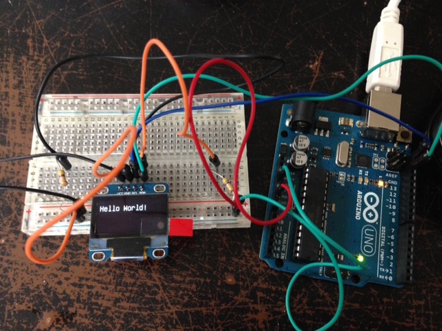
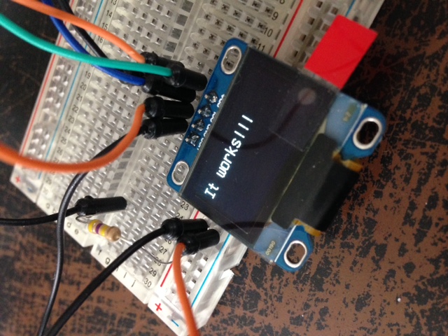
To test the OLED screen, the I2C wiring configuration, and the simple program from the U8glib library, I used an Arduino Uno and a breadboard. I was able to verify that everything was working, so now I just need to transfer that to my own board design.
One thing that is likely to be causing a problem is the power. The OLED screen runs on 3.3V, but the board I designed didn't provide any way to change the 5V provided by the USB port. In addition, it shouldn't be running off the USB port at all, since it will be a free-standing piece in my classroom. And finally, I want the OLED screen to attach to the back of the board, not the front, so I can mount it inside the base with the screen in the base's cutout. With all those changes in mind, I redesigned the board again. Hopefully this will be the one that works, that I can produce multiple times - one for each spacecraft.
In my classroom I will be able to access the internet via an Ethernet cable, so I'm not really concerned about the SSH/Wifi sharing issue I mentioned previously. So on the Raspberry Pi front, my focus has been to get it to access a NASA RSS feed. In looking for those feeds, I found that that's not how the ISS sends its "Spot the Station" alerts, which is pretty obvious after thinking about it - those depend on the user's location, so an RSS feed wouldn't work. However, the feed of the Curiosity rover (always a favorite among students), and all the other NASA missions on Mars, can be accessed at the Mars Exploration site. There are also a number of tutorials online with different ways of accessing the feeds using the Raspberry Pi and Tiny Tiny RSS, Fever, or Feedparser. I plan to start with the last one, since it also references displaying those feeds not on a monitor, but on a smaller screen (in the case of the tutorial, an LCD screeen).
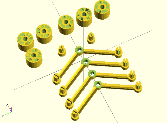
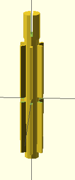
Feedback from the initial project presentation was that I should do the 3D modeling for the spacecraft myself instead of downloading it. Fair enough - it's definitely a skill I should keep working on. Since I think the Curiosity rover will be a good, frequently-updated feed, I made a (simple) model of that. From the Thingiverse version, I used the idea of designing it in parts that will be assembled:
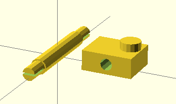
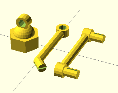
Similarly, I modeled the New Horizons spacecraft in parts:
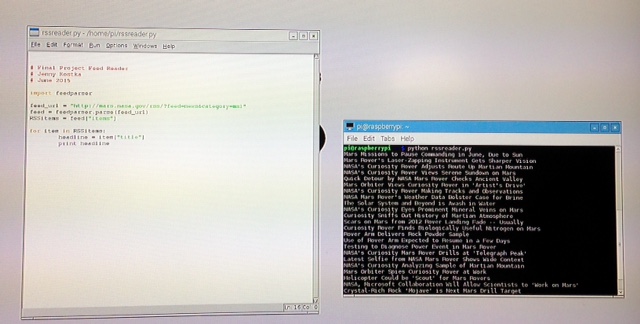
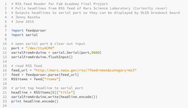
Continuing with the programming, I installed Feedparser on the Raspberry Pi and adapted a Python script from Getting Started with Raspberry Pi to pull the Curiosity's headlines. Success!
Today was a productive day!
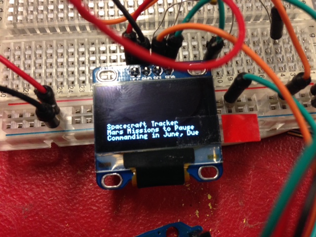
To have the feed display on the small screen, I added to the Python program some code to write the output to the serial port instead of just printing it. I then adapted a corresponding program (borrowing from the U8glib library code) in the Arduino environment to read that data from serial and send it to the OLED screen using I2C. It took a bit of debugging, but eventually the code worked.
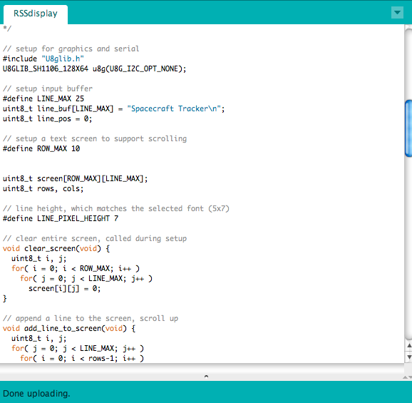
Verifying that the code works using the Arduino Uno:
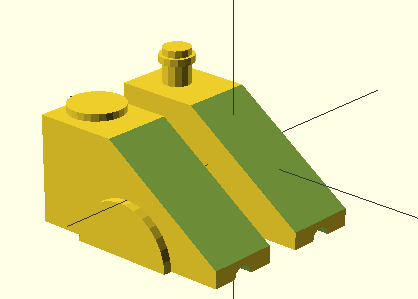
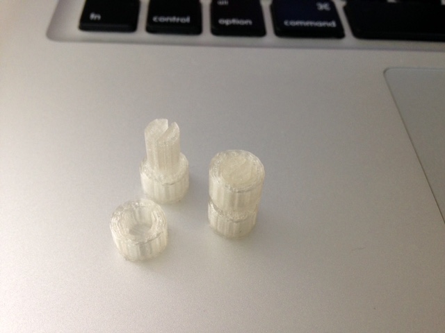
I started 3D printing the models, first doing a test of the holes and pegs I'm using to attach all the parts together. I had to print the hole and peg a couple of times to get the size right, but once I did I could adjust all the other parts so that I know they'll fit. Since I know they're going to take ~4 hours to print, I set them up to print tomorrow.
The last piece I worked on was the base. Again, I did a test, this time cutting out a section of the living hinge, to verify that it worked before cutting out and assembling the whole base. Everything fit together well, even if it wasn't a perfect press-fit.
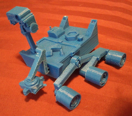
Today I finished the 3D printing and assembly of the Curiosity model. Compared to those I had found online, it's quite simple, and the scale is not quite right, but it is satisfying to have done the design myself.
Lastly, I had been unable to mill my circuit board due to a spate of broken endmills (several people had success milling with the broken-off end, but my board just had too many fine traces), but today new ones finally arrived and I was able to mill and stuff the board.
I started trying to program with code I had tested earlier, but it didn't work right away, so my next steps will be troubleshooting.
For the electronics this week, I focused on troubleshooting. Checking all the connections showed that everything had been soldered correctly (phew!). It turned out the problem was the resonator I had used - 20MHz instead of the 16MHz I needed for the ATMega. Once I had switched that out, I was able to program the board with the code I had written earlier.
The last remaining problem to solve was getting it to work with the Raspberry Pi in the same way the Arduino/breadboard/OLED screen setup had. This was not quite straightforward; I had trouble initially getting my board to talk via serial. Eventually it worked, but I had to lower the baudrate to 4800. I still don't love the way the display looks, how it's at the bottom of the screen and the headline doesn't quite fit, but the program works.
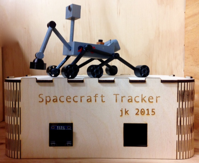
In addition to working on troubleshooting, I also worked on the Curiosity model. I decided I wanted to paint it, to try to add more detail to an otherwise quite simple model. I used enamel paint for model cars to do the entire body and wheels, plus details on the antenna, camera lens, grappling arm, and the NASA and JPL logos.
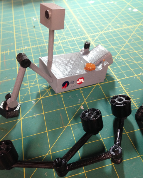
Then, amazingly, all that was left was putting it together!
Unfortunately, trouble persisted. The problem can be narrowed down to the serial communication, because the Pi will display the headlines on its own terminal (so the Feedparser program is working) and the OLED board's code will compile and the screen will display the buffer text (so the I2C communication is working), but the headlines aren't making it from the Pi to the screen reliably. In troubleshooting, I've tried lowering the baudrate (which did work initially), using a different FTDI cable (a USB Bub), and switching to software serial in the Arduino code.
To figure out what was going on with the serial communication, Shawn and I tried programming the board with simpler programs (both Blink and one that displays the ASCII table via serial) and checking with an oscilloscope to see what is going on. Finally we found that I had made the mistake of switching TX and RX in my board design. Rather than redo the board, I switched the pins specified in the software serial part of the code. Finally it works!!
Jenny Kostka Fab Academy 2015
