Output Devices
Hello Stepper (Unipolar Stepper Motor Board)
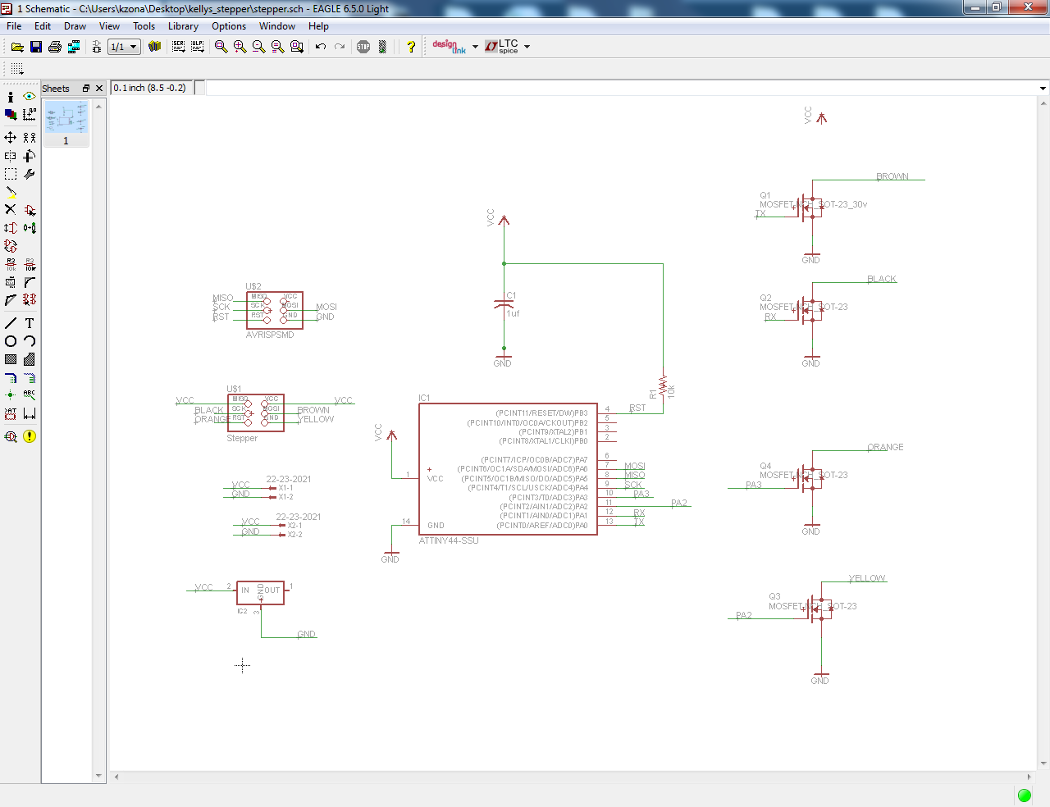
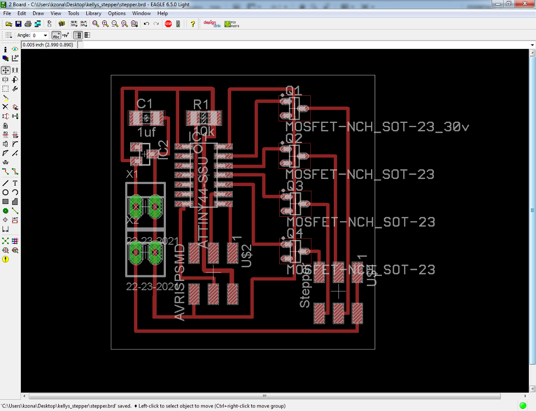
I began by designing a stepper motor driver board in Eagle. This was quite easy after having designed a simpler stepper driver board. This design only required a few more components, including a microcontroller, resistor, capacitor, and a regulator.
Hello Stepper schematic and board files available here
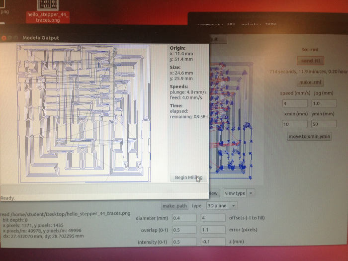
I exported a png from Eagle and loaded it into Fab Modules. Here is my workflow:
Terminal: type "fab"
Choose "png" to "rml", 500 dpi
Load png
Settings: 1/64" bit
Diameter (mm): 0.4 Overlap (0-1): 0.5 Intensity (0-1): 0.5 Offsets (-1 to fill): 4 Error (pixels): 1.1 Z (mm): -0.1 Speed (mm/s): 4
>Make Path >Make rml >Send It!
TIP: Place the bit in the collet as you normally would. When you lower the bit, you will most likely hit the lower limit and have to loosen and drop it to the top surface of your material. But BEFORE you do this, raise the spindle slightly. Then when you do drop the bit to the material, you will not hit the lower limit, ie. you will give yourself more z-depth so that you can actually cut down into the material.
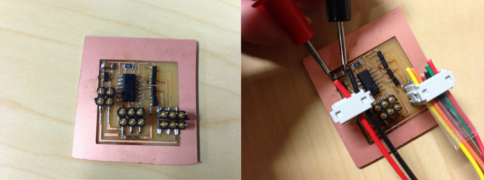
I was having some issues with my first few boards. I used a multimeter to measure the voltage across the capacitor and found that I had a bad connection. After re-soldering, everything was fine.
Programming
My last step was to program the board to get the motor to run. The C code I used to program the motor is available here: http://academy.cba.mit.edu/classes/output_devices/stepper/hello.stepper.44.full.c
This section of the code was edited as follows:
#define on_delay() _delay_us(600) // PWM on time
#define off_delay() _delay_us(5) // PWM off time
#define PWM_count 190 // number of PWM cycles
I used Atmel Studio to upload the code:
Atmel Studio
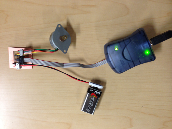
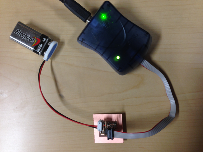
Connect the Hello Stepper Board's J1 ISP Header to the AVRISPmkii, and connect the AVRISPmkii to the computer via the USB cable.
Connect the Hello Stepper Board's J2 Header to the power supply. You should get a green light on the AVRISPmkii.
New Project> GCC C Executable project Device Selection> ATtiny44A
Erase all of the instructional text that is already in the command window (where it says "... Please write your application code... etc. ...") Paste the C code into the command window. The code to do a half-step for the unipolar stepper board is found here: http://academy.cba.mit.edu/classes/output_devices/stepper/hello.stepper.44.half.c
Save File
Build> Compile (you should not get any error messages, warnings are sometimes OK)
Build> Build Solution (this generates the .hex file, which is what the microcontroller reads)
Tools> Device Programming: [Tool: AVRISP mkii, Device: ATtiny44A, Interface: ISP] > Apply. >Target Voltage- Read (should be 5V) >Device Signature- Read
>Memories- Click on the ellipses next to Flash and navigate to the folder where your project is saved. There should now be a .hex file in there. Select this file, then hit the 'Program' button. This should give you a "verified" message, so that you know the device has been properly programmed. I connected the motor to the J3 Stepper Header and watched it run back and fourth!
output device from Kelly Zona on Vimeo.
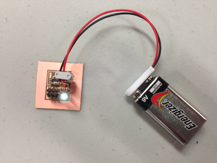
Hello RGB LED
In addition to the stepper driver, I also decided to try making an LED output device.
In Fab Modules, I loaded the png of my board. Here are my settings: 1/64" bit Diameter (mm): 0.4 Overlap (0-1): 0.5 Intensity (0-1): 0.5 Offsets (-1 to fill): 4 Error (pixels): 1.1 Z (mm): -0.1 Speed (mm/s): 4
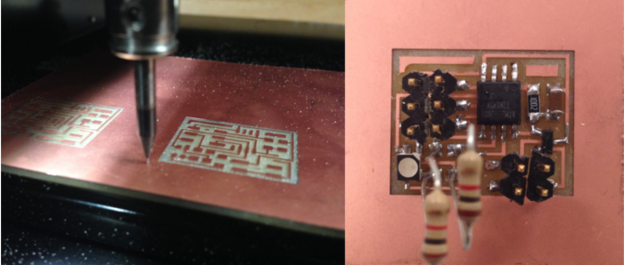
One thing to note is the orientation of the LED. There is a factory mark in one of the corners. It should point toward the microcontroller, as seen in the image above. I had to use through-hole 1K resistors as I was out of SMT ones.
To program the board I used the C code found here: http://academy.cba.mit.edu/classes/output_devices/RGB/hello.RGB.45.c
Programming in Atmel Studio
Connect the Board's J1 ISP Header to the AVRISPmkii, and connect the AVRISPmkii to the computer via the USB cable.
Connect the Hello Board's J2 Header to the 5V battery power supply. You should get a green light on the AVRISPmkii.
New Project> GCC C Executable project Device Selection> ATtiny45
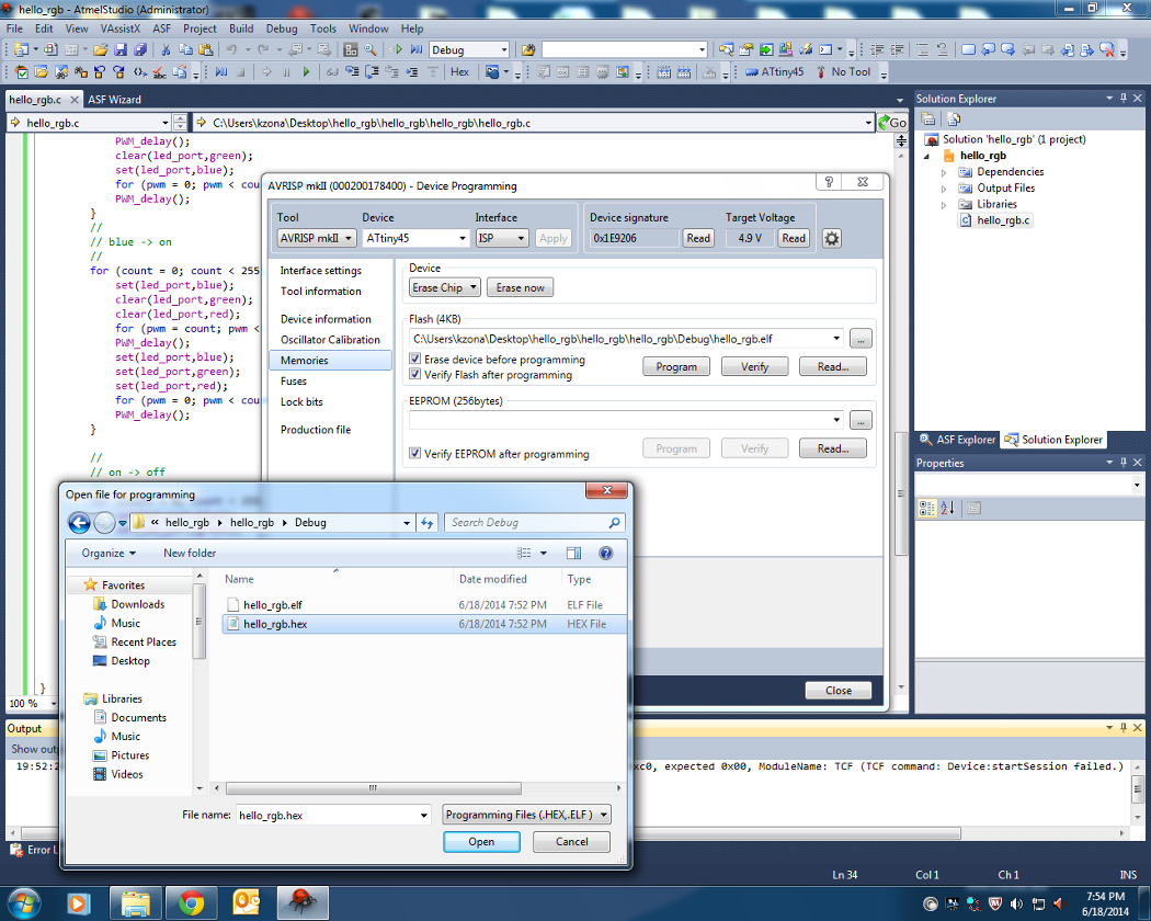
Erase all of the instructional text that is already in the command window (where it says "... Please write your application code... etc. ...") Paste the C code into the command window.
Code available here: http://academy.cba.mit.edu/classes/output_devices/RGB/hello.RGB.45.c
Save File
Build> Compile
Build> Build Solution
Tools> Device Programming: [Tool: AVRISP mkii, Device: ATtiny45, Interface: ISP] > Apply. >Target Voltage- Read (should be around 5V, mine read as 4.9) >Device Signature- Read >Memories- Click on the ellipses next to Flash and navigate to the folder where your project is saved. There should now be a .hex file in there. Select this file, then hit the 'Program' button. This should give you a "verified" message, so that you know the device has been properly programmed. Success!